|
|
Post by Doug on Jan 24, 2015 11:08:50 GMT
hi after having the exquisite pleasure of making some young children cry because my loco broke down, again! I have finally decided to fix my piston rings, so far I have had; original orings 50 year old rubber. These seized solid under steam packed granite string. Worked very well indeed until they started to get "cleaned" by the steam silicon o rings. They also seized under steam but only after a couple of runs. the reason for this is in hind sight probably a poor fit without enough expansion room however, so after all that lot I have decided to use PTFE my question is to all the people who have used PTFE successfully what fit should I use obviously I have machined the outer diameter to a nice sliding fit but do I need any lateral space, my speedy Pistons shown below are a snug fit laterally is this wrong? The old silicon O ring it's obviously had a hard time 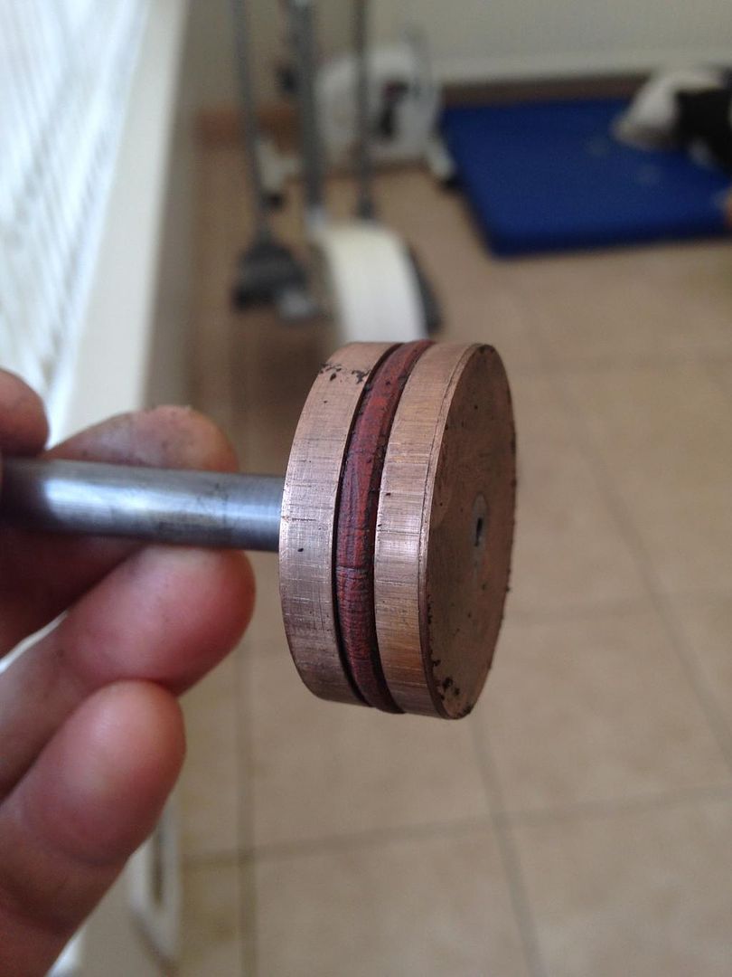 The new Speedy ring in PTFE 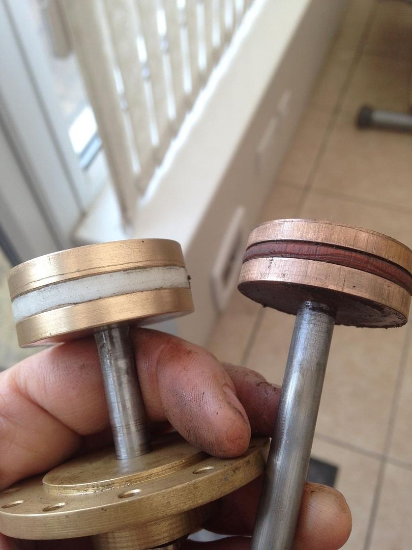 Please help as I dont want to have to go through the drama of being pushed back to the station again |
|
|
|
Post by Deleted on Jan 24, 2015 11:35:27 GMT
Sorry matey, can't help you with the tech. stuff as I use "Traditional" Iron-within-Iron, but I do know that feeling of "Failing within section" only too well...........The centre slide valve moved on my Scot whislt carrying what I can only describe as the real St. Trinnians train from Hell !!..... Please believe me when I say you have my deepest sympathy !!........RiP.
|
|
|
|
Post by Deleted on Jan 24, 2015 12:57:27 GMT
Hi Doug,
It looks as though the bores are probably not smooth enough for O rings anyway. The bore needs to be lapped and polished to a very good finish to get any reasonable life out of them. They also don't want to be too tight a fit. The fits given in the O ring data manuals are far too tight for our use. I don't think silicon O rings are the ideal choice either as they are too soft. You would have been better using Viton. The PTFE will be a lot better though.
I can't give you a definite answer to the clearances needed as I just 'guestimate' but you need some side clearance and clearance in the inside bore of the ring to allow the PTFE to expand. I would suggest say 0.005" side clearance and 0.010 clearance on the inner bore as a start. You will also need a gap in the ring to allow for expansion, assuming the rings are split? If you are using just the one ring the ideal is a stepped gap so the ends overlap. I use two thinner rings side by side with the gaps at 180° apart so there is no leakage.
I would imagine the Butch cylinders are something like 1.5" bore? You may find that virgin PTFE does not have enough spring in it to seal the ring against the bore adequately and you may need an O ring underneath. I've not used PTFE rings above 1" bore yet so can't be sure. Another alternative is to use graphite filled PTFE for the rings. This is much harder and springier than virgin PTFE and perhaps better suited to the job. I intend to try it next time. The only thing is that it needs to be machined to finished size pretty much like a cast iron ring. i.e. machine the outside oversize, gap the ring, and then machine the outside diameter to finished size with the ring compressed.
John
|
|
|
|
Post by Doug on Jan 24, 2015 18:14:15 GMT
Thanks John that sounds great I will have a go at making them I have used a diagonal cut in the ring on the speedy ones I like the idea of two thin ones that sounds like a great idea hopefully I can get butch to run reliably so I can do a few running days this year, ( there are never enough steam locomotives running on the open days IMO). This last hurdle should make all the difference as I nearly got it running perfectly last year it's just these darn rings giving me issues.
all the best
Doug
|
|
SteveW
Elder Statesman

Posts: 1,399
Member is Online
|
Post by SteveW on Jan 24, 2015 21:28:06 GMT
Guys, years ago on the ancestor to this forum was a similar discussion on using 'o' rings. In essence when used on a sliding fit as per piston rings the slot they live in has to be wide enough to allow then to roll back and forth. That old thread also included a link to an app note that detailed the extra width necessary.
|
|
|
|
Post by Deleted on Jan 24, 2015 23:08:20 GMT
Hi Doug
As John says PTFE requires a little guesswork...i did a little research including reading John's own words on the subject when doing the PTFE rings for 4470....you'll find the details in the 'project 2, Heilan Lassie build' . I turned down some PTFE bar until it was slightly larger than the bore size( detail should be in my thread), this means that once you have cut the ring you need to then compress it to fit in the bore. You can then gap it just like a piston ring on a car allowing a big enough gap to take into account it's expansion, bear in mind PTFE iirc expands about 16x more than steel. you also need to make sure that the groove that it sits in is correct for the inner diameter of the ring so that it has enough room to expand without jamming. I think you have a lot of leeway here though as PTFE when heated is fairly soft and thus is more likely to form allowing for the expansion without seizing the piston although I would assume if you get it really wrong this could still happen, a case of trial and error should do. I fitted two rings into a single groove on my loco....there was a great improvement using PTFE and the loco still ran fine on air after steaming. I don't see the need for an O ring to sit under the PTFE to push it against the bore wall...if sprung as I stated and with it's expansion rate in relation to the metal around it the ring will seal fine.
regards
Pete
|
|
jma1009
Elder Statesman
Posts: 5,901
|
Post by jma1009 on Jan 24, 2015 23:16:43 GMT
i think that pete's comments are very valid.
unfortunately because braided graphite asbestos square section packing is no longer available (banned) via the ME suppliers (it still crops up on ebay and if i see some i buy it!) a suitable alternative is required. (the substitute sold by the ME suppliers is useless in my opinion being plastic rope coated in graphite powder).
my own experience of 'O' rings in pistons was not good and confirmed what others have stated above, and i have stuck to the old fashioned braided square section graphite asbestos packing - which if properly fitted will last a very long time and is also quite forgiving in cylinder bores that arent perfect (though i do always lap mine to remove machining marks and leave a perfectly smooth finish due to my poor lathe boring skills).
ordinary 'O' rings are useless in pistons as is graphite asbestos string, as unfortunately doug has found out the hard way!
cheers,
julian
|
|
chrisb
Part of the e-furniture

Posts: 345
|
Post by chrisb on Jan 24, 2015 23:56:46 GMT
If you look for industrial supplies you can get 3mm/ 1/8" square section woven graphited ptfe gland packing which may do a similar job to the old asbestos rope.
|
|
jma1009
Elder Statesman
Posts: 5,901
|
Post by jma1009 on Jan 25, 2015 0:04:20 GMT
hi chris,
when you bend the rope you mention eg to fit into a piston the graphite simply falls off. as a result solid turned PTFE rings are going to be far superior.
cheers,
julian
|
|
|
|
Post by Deleted on Jan 25, 2015 1:14:08 GMT
I think Chris may be refering to the square braided PTFE gland packing that doesn't contain graphite? I used that on the 3.5" Princess Royal but it hasn't done very much running so I don't know how it will hold up long term. It seems ok so far.
John
|
|
chrisb
Part of the e-furniture
Posts: 345
|
Post by chrisb on Jan 25, 2015 9:04:56 GMT
|
|
isc
Statesman
Posts: 708
|
Post by isc on Jan 25, 2015 9:31:33 GMT
On my Stirling Engines I use graphite impregnated PTFE for gland bushings. isc
|
|
|
|
Post by Deleted on Jan 25, 2015 11:40:33 GMT
|
|
|
|
Post by Doug on Jan 25, 2015 17:07:38 GMT
Thanks Guys, PTFE rings made and fitted let's see how this goes. I will try for next weekend if the weather plays ball.
I will post the results, although I will have a few runs first because the O rings worked the first three runs.
all the best Doug
|
|
|
|
Post by Doug on Mar 22, 2015 15:25:47 GMT
Finally got a run in with the new piston rings and Buch has got his chuff back!
I ran for an hour and a half with great results it was the longest single run I have done to date and not even a hint of it tightening up.
i then got to try a loaded run as one of the members wanted a chassis towing round to free it up. So with the chassis in tow loaded with bricks I did a couple of laps in full gear and again worked very well it sounded like an engine with a very crisp exhaust note.
i am super pleased.
|
|
|
|
Post by Roger on Mar 22, 2015 22:56:53 GMT
That's excellent news, and thanks for sharing the video. How did you make them in the end? I presume they're slit? If so, how did you decide on the fit etc?
|
|
|
|
Post by Doug on Mar 23, 2015 6:19:37 GMT
That's excellent news, and thanks for sharing the video. How did you make them in the end? I presume they're slit? If so, how did you decide on the fit etc? I made them a sliding fit in the bore then cut them diagonally, the theory is that the lateral movement in either direction will push the two surfaces together, it seems to be very effective I could tell the difference as soon as I moved off it felt so much more powerful. During driving I couldn't notch up any more, it ran fine almost in mid gear and with very little regulator open. its such a simple fix I am happy to continue with speedy now as it has exactly the same fit on the rings.  |
|
|
|
Post by joanlluch on Mar 23, 2015 7:37:48 GMT
Did you allow for some clearance on the insider bore of the ring and the other clearances that John (baggo) suggests? How deep (or thin) is the rings? I mean difference between the inner and the outer diameter. Did you use any particular filled grade of PTFE? In case of using two split rings with the cuts set apart 180º, are they supposed to stay that way or should you use some method to prevent them to rotate? As an additional note, I found that PTFE is not working right for everyone. See this (piston valve attempt) www.modelengineeringwebsite.com/PTFE_valve_rings.html . In this case I think the problem could be that no clearance was allowed at the inner bore of the rings and that the rings were probably too deep to adapt to temperature expansion. |
|
|
|
Post by Doug on Mar 23, 2015 10:36:21 GMT
Did you allow for some clearance on the insider bore of the ring and the other clearances that John (baggo) suggests? How deep (or thin) is the rings? I mean difference between the inner and the outer diameter. Did you use any particular filled grade of PTFE? In case of using two split rings with the cuts set apart 180º, are they supposed to stay that way or should you use some method to prevent them to rotate? As an additional note, I found that PTFE is not working right for everyone. See this (piston valve attempt) www.modelengineeringwebsite.com/PTFE_valve_rings.html . In this case I think the problem could be that no clearance was allowed at the inner bore of the rings and that the rings were probably too deep to adapt to temperature expansion. Hi Joan I did not allow for extra clearnce, the rings were a fairly snug (not tight) fit. the rings are aproximately 1.6mm (1/16") thick made from standard PTFE, i understand that graphite PTFE is better for wear though. I used one solid ring with a diagonal cut the steam pressure & the direction of movement pushes the two surfaces together to seal it and it seems to work. in that article i can see the issues very clearly; 1 the rings are too big (deep) the expansion will be too great to work effectivly. 2 the rings have no containment on the sides (PTFE gets very squishy under heat) so the timing will go to hell. do i think i have the best solution... no not at all but it is very effective |
|
|
|
Post by Roger on Mar 23, 2015 19:05:31 GMT
That's excellent news, and thanks for sharing the video. How did you make them in the end? I presume they're slit? If so, how did you decide on the fit etc? I made them a sliding fit in the bore then cut them diagonally, the theory is that the lateral movement in either direction will push the two surfaces together, it seems to be very effective I could tell the difference as soon as I moved off it felt so much more powerful. During driving I couldn't notch up any more, it ran fine almost in mid gear and with very little regulator open. its such a simple fix I am happy to continue with speedy now as it has exactly the same fit on the rings. That's a great result, it clearly works well. I'm assuming that the saw cut is just about the right amount to accommodate the expansion when it gets hot. If the gap wasn't quite enough, it might be able to cope with that, and if it was too much it would noticeably leak. Did you use a standard hacksaw to make the cut? |
|


