|
|
Post by simon822 on Jan 24, 2015 21:23:27 GMT
Would anyone be able to help me with any information for the following on a Ken Swan Wren?
1. What size are the springs, leaf width, thickness and number of leaves. The ones on it seem far to weak, and the engine is bouncing around, which I suspect is upsetting the valve gear. I have discussed putting in rubber washers, but would like to know the correct rating of the springs before I add the rubber washers.
2. What is the design and size of the regulator and the steam pipes, the engine feels a little short of steam, end in full gear with full regulator.
3. I believe that the design for the grate includes a rocking grate, is this a simple fitting, since the current grate is a fixed grate, which was a real pain tonight when raking out the fire.
Any help would be very welcome,
Regards,
Simon.
|
|
uuu
Elder Statesman
 your message here...
Posts: 2,808
|
Post by uuu on Jan 24, 2015 21:33:34 GMT
I can't answer your questions, but I can comment on one that I have driven.
It was very softly sprung, but this didn't feel wrong at all, it just loped around a lot.
No way was it short of steam. You could move off with a low fire, and with an organ-pipe pom-pom-pom-pom from the chimney, the pressure gauge would tick gently upwards.
I hope you can get your sorted.
Wilf
|
|
jma1009
Elder Statesman
Posts: 5,901
|
Post by jma1009 on Jan 24, 2015 21:56:38 GMT
hi simon,
i have driven many times the same Wren as wilf above. the loco was built by a very capable engineer and model engineer who stuck to the drawings throughout. it performs extremely well and does everything you would expect a good loco to do, despite (as designed) having no superheaters. the grate wasnt a rocking grate. the loco is very sure footed and i dont recall any problems with the springing or the valve setting being upset.
what you describe as faults could be due to any manner of things and not necessarily any fault of the loco. there might be a steam leak somewhere, or insufficient steam oil lubrication, or poor coal, dirty or blocked tubes, or dare i suggest bad driving and firing. if you listen to the sound the loco makes it will tell you an awful lot about what may or not be wrong.
if you dont have a set of drawings i would recommend you obtain a set from Ken.
cheers,
julian
|
|
chrisb
Part of the e-furniture

Posts: 340
|
Post by chrisb on Jan 24, 2015 23:11:39 GMT
For info, Polly Model Eng are now agents for Ken's Wren and Koppel designs
|
|
|
|
Post by marshall5 on Jan 24, 2015 23:16:48 GMT
Simon, On the Wren I was building (to Ken's drawings) the main steam pipe was plenty big enough. The regulator port was 3/8 x 3/8 with a 30 deg. 'lead' at one end. The grate had an off-centre pivot so, whilst not truly a rocker, did tip and dump the fire when the operating lever was lifted. One of our club members also had one,also built to the drawings, which steamed like a witch and would pull heavy loads all day. I'd be tempted to look at the valve setting for the cause of the lack of power. One of the acknowledged drawbacks of Hackworth gear is that it is affected by how the loco is 'sitting' on its springs. Hope this helps. Ray.
|
|
jma1009
Elder Statesman
Posts: 5,901
|
Post by jma1009 on Jan 24, 2015 23:32:46 GMT
re ray's very valid comments,
you will know instantly if the valve gear is set ok by the beat and any syncopation plus what happens to same when notched up. the Wren i quoted initially ran on quite a rough 7.25"g track, and although wilf refers to it 'lolling about' the gear could be notched up perfectly ok (and of course when notched up less steam is used).
the chimney is very long, and one thing i would check carefully is the concentricity of the blastpipe with the chimney. as ray has also commented there should be no problem with the steaming of the loco - it is an excellent design (apart from lack of superheaters!). but buying a loco built by someone else you cant be sure everything is put together quite how it should be
when i was a volunteer on the Talyllyn Railway i remember the late roy smith carefully checking No.4 Edward Thomas's valve gear at the start of the busy season early august. but this was very much a matter of ultra 'fine tuning'.
cheers,
julian
|
|
|
|
Post by simon822 on Jan 25, 2015 19:41:31 GMT
Thanks for all the input from everyone so far, especially to Ray for the information relating to the drop grate. As you may have noticed, I have also created a thread looking for the drawings for the Wren. Thanks for the information regarding Polly Engineering, I will investigate this avenue, but in anyone can help regarding a set of drawings I feel it might be easier.
I understand the short comings of Hackworth valve gear having driven several full size locomotives with Hackworth valve gear, so as ray states it is the way it sits on the springs which is important, hence my desire to improve the springing prior to setting the valves. I will be checking the valves next weekend, but I suspect the rocking opens/closes the valve nearly 50% of the opening.
There is no problems with the steaming of the engine, the blast pipe has already been changed for a much more efficient blast pipe, I would also be interested in knowing the diameter of the blast nozzle, but believe that the nozzle I have installed is larger than the design, but better alignment and design creates more draught with less back pressure.
Kind regards,
Simon.
|
|
|
|
Post by marshall5 on Jan 26, 2015 9:36:20 GMT
Sorry I can't help you with a set of drawings as mine were sold with the loco. I do have tatty copies of sheets 1&2 (the G.A.)and A4 photocopies of a lot of bits which I scribbled on and used in the workshop so might be able to answer specific questions. The designed bore of the blast nozzle is 13/32" for instance. My Wren was quite firm on its springs (unlike my Milner Hunslet which despite uprated coil springs still bounces about) - I suspect they may have been stiffer than designed. Glad to help.
Cheers, Ray.
|
|
|
|
Post by simon822 on Jan 31, 2015 22:18:27 GMT
I have taken a couple of photos of the current spring arrangement.
Having had a little think about this, I think the simplest solution would be to replace the beam with a leaf spring, and remove the coil springs. I note the white rubber, this was supposed to firm up the suspension, but doesn't do anything!
I have thought about just replacing the coil springs with firmer springs, but would prefer to have a go at making the leaf springs. The question is how to calculate the stiffness of the new ones so they are the same as the design.
Kind regards,
Simon.
|
|
|
|
Post by simon822 on Jan 31, 2015 22:18:53 GMT
Hmm, attachments didn't work! |
|
|
|
Post by simon822 on Jan 31, 2015 22:44:11 GMT
Photos 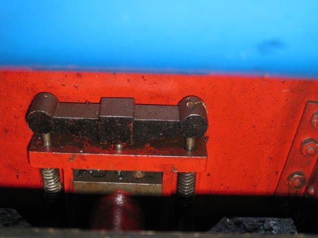 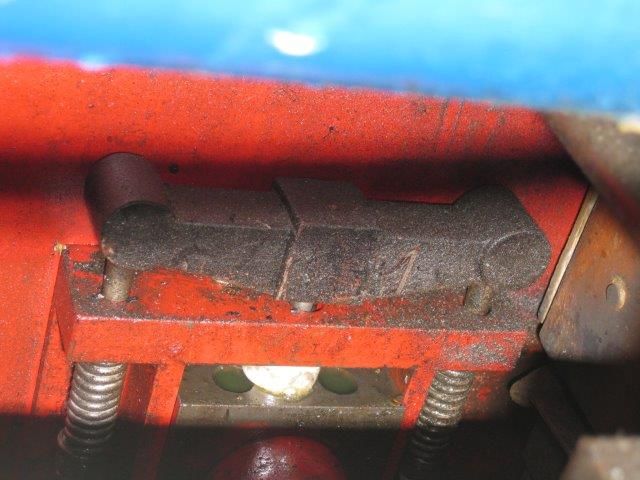 |
|
|
|
Post by simon822 on Jan 31, 2015 22:57:46 GMT
Sorry about the number of Posts, but I'm currently trying to find a way of adding photos, I think it will make things a bit easier to understand. The steam pipe to the cylinder does not look correct, since it has a 90 degree union where it passes through the smokebox. I will be doing a steam chest pressure test tomorrow. 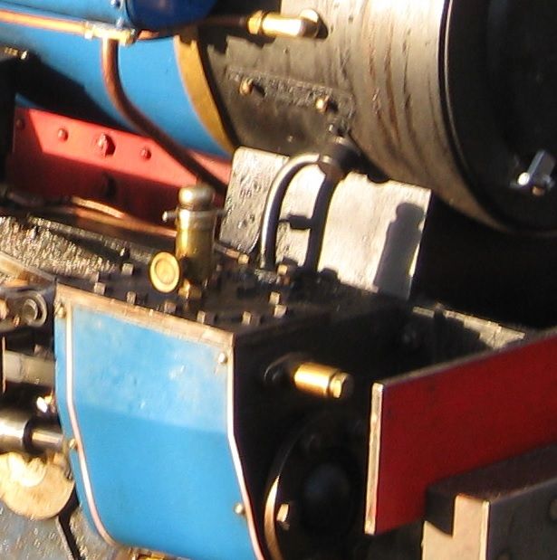 It just looks wrong to me? Regards, Simon. |
|
|
|
Post by Roger on Feb 1, 2015 8:11:19 GMT
You have to add your photos to a site like Photobucket or Flickr and copy the link into you post, there's no facility to attach photos any more, they take too much space. There's a long thread about how to do this for each type or site, so it you search the Forum for Flickr for example, you should see how it's done. Those sites are free and it's easy to do. It also provides a nice album of your work.
|
|
chrisb
Part of the e-furniture
Posts: 340
|
Post by chrisb on Feb 1, 2015 16:02:38 GMT
Both the horns and the steam pipes look nothing like the drawings.
|
|
|
|
Post by simon822 on Feb 1, 2015 18:51:34 GMT
Thanks for this information chris. I have had a good day at the track today. With a load of approximatlt 2000kg, full regulator only equalled 40psi at the steam chest for most of the time. Fast running it dropped towards 30psi. When it stalled on the bank, full pressure was registered on the steam chest, but as soon as it moved this dropped to 60psi, then down to 40psi within a couple of revolutions. As for the oscillation, this was still pronounced which under test showed nearly 1/8 inch movement of the valve in full gear.
So my thoughts are these are the first 2 areas for me to focus on. The only question is should I build a new regulator, or continue to use the existing one.
I will post a couple of photos later if they are not all blured!!
|
|
chrisb
Part of the e-furniture
Posts: 340
|
Post by chrisb on Feb 1, 2015 19:05:29 GMT
As drawn the regulator is on the front tube plate in the smoke box and the steam pipes are 3/8" od. If your boiler has the mounting pad with 3 screws on the smokebox tube plate then yes you could retro fit the correct regulator and steam pipes.
|
|
|
|
Post by simon822 on Feb 1, 2015 20:31:08 GMT
Well these are the photo's. Full Gear, Full Regulator with plenty of pressure: 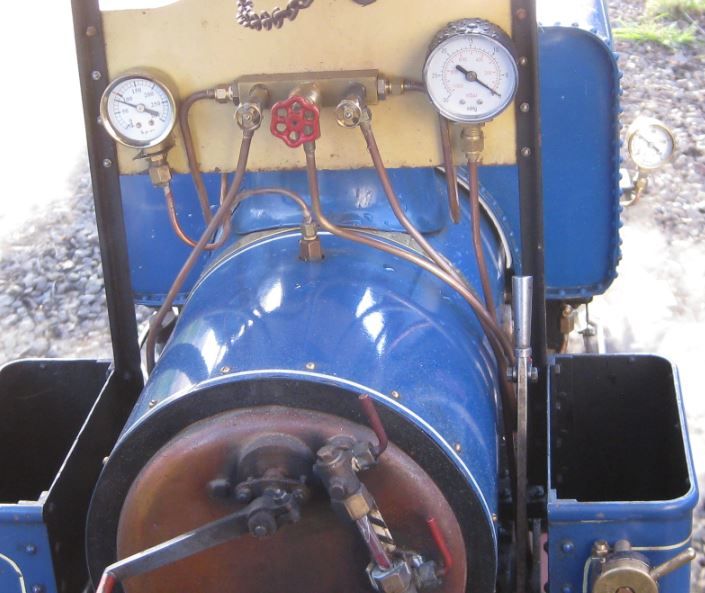 Note the main pressure gauge is reading 85psi and the valve chest is reading 40 psi (Different gauges main gauge will be changed for the 0 - 150 in due course). The speed here would have been a slow walking pace (IF that) 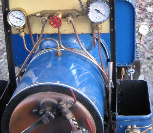 This one has the same readings, but notched up, the speed would be about walking pace. Only when starting does it seem to have any power. |
|
|
|
Post by joanlluch on Feb 1, 2015 21:31:53 GMT
Simon, Please can you clarify this from a point of view of the language "Note the main pressure gauge is reading 85psi and the valve chest is reading 40 psi (Different gauges main gauge will be changed for the 0 - 150 in due course)." I am not native English speaker, so I have trouble at understanding where is the pressure picking point for the "main pressure" and "valve chest". Previously you were talking about the "steam chest". That's just a vocabulary issue, I would appreciate that you clarify that for me. Thanks in advance.
|
|
|
|
Post by simon822 on Feb 1, 2015 21:58:51 GMT
Sorry, it was probably a bit confusing:
Main pressure gauge is the one connected to the boiler Left side of photo
Steam chest or valve chest is one connected to the top of the cylinder right side of photo.
The part about changing the gauge is that it is customary for an engine working at 90 psi to use a gauge capable of 1.5 working pressure i.e. 135 and the nearest is 150 or 160 rather than the 300 psi currently fitted.
The aim of the exercise was to measure the loss between the regulator and the cylinders. It appears that only about 40 psi gets to the cylinders, which is not really enough when climbing our bank with a half load.
Hope this clarifies the situation.
Regards,
Simon
|
|
jma1009
Elder Statesman
Posts: 5,901
|
Post by jma1009 on Feb 1, 2015 22:44:21 GMT
hi simon,
i agree with chrisb that the horns springs and steam pipes look nothing like the drawings. this rather begs the question what other liberties the original builder took with the excellent ken swan design? the external steam pipes look ridiculously small.
when you receive the drawings you need to take a good look at them and how they compare with your loco. i suspect you may find a few surprises that will explain why your loco doesnt 'sparkle' performance-wise like other 'Wrens'. obviously there is no point replacing part of the steam circuit if there is a restriction elsewhere in the system. you also have to take into account that the 'Wren's' saturated steam is less fluid than superheated steam and so less forgiving to a poor steam circuit. plus there is more of a risk of the steam condensing in the cylinders which seriously impedes efficiency plus the ability to notch up when comparing saturated to superheated steam. i dont recall any such problems with the 'Wren' i used to regularly drive built in accordance with the drawings.
coil springs are always a bit more bouncy than proper leaf springs, and i would strongly recommend fitting proper leaf springs as per the drawings. ken was quite proficient at working out what was required for leaf springs and although it is many years since i studied the drawings they contained very comprehensive details re proper leaf springs if my memory is correct.
cheers,
julian
|
|


