jools
E-xcellent poster

Posts: 200
|
Post by jools on Dec 11, 2017 21:47:49 GMT
I agree with Reg's comments, you can also click on the lines and grab the blue grip box dragging it to the grip box on the line you want it to meet, or use the extend command.
tangents are a bit more involved and i haven't discovered a real accurate way to radius a straight line into a curve as in a linkage eye. I generally draw a line from the straight line to a tangent of the circle, then trim the parts till they look ok then grab the grips and drag to the ends.
I suspect there is a more "professional" method.......
Jools
|
|
|
|
Post by atgordon on Dec 12, 2017 2:22:40 GMT
I am glad that folks are offering advice to those needing help. Can I make a suggestion so those with expertise with a particular CAD/CAM package can offer more targeted help?
It would be helpful to me (and hopefully others) if the Poster made clear what package they were using when they post a question or comment ... for example, I know how to draw tangents to circles in 3 packages, but without knowing what CAD/CAM package the Poster is using makes it difficult to know if I can help ...
|
|
peteh
Statesman
 Still making mistakes!
Posts: 760
|
Post by peteh on Dec 12, 2017 4:00:14 GMT
The other option to join the lines is the fillet command, with radius set to 0. As always with cad many ways to do the same job. For the tangent line to two circles - draw the circles in the right place (it helps  ) then Line, tan (pick on first circle near to where the tangent will be), tan (pick second circle near where the tangent will be) Works for Autocad and it's clones - Draftsite, Progecad, Intellicad and so on. You're not a luddite Silverfox because you are trying! |
|
|
|
Post by Roger on Dec 12, 2017 7:20:30 GMT
To join up two straight lines with a slight gap between them you can usually use the Chamfer command. You set each leg of the chamfer to 0 (zero) which actually produces a corner rather than a chamfer. Clicking on the Chamfer command then each of the two lines you want to join will join them. Reg Alibre has a specific command for this, but for some reason it doesn't work with curved lines |
|
|
|
Post by 92220 on Dec 12, 2017 9:30:48 GMT
Bob The info both you and Malcolm High supplied, was pearls beyond price ( or something like that) and like riding a bike, it is easy when you know how lol What i did find is how sensitive the joining of lines are. I had to enlarge to the Nth degree to find out that there was a gap that just showed up, but the programme wouldn't jump it. by deleting the offending bit jutting out and redrawing the line. bingo! Nearly finished all the plans, and your suggestion of converting them to Sline is going to be taken on board The only drawback is after drawing the part and doing the polylines and the J command, when one of these miniscule gaps is there, i cannot delete either of the offending lines and redraw, as when i deleted it, the whole of the polyine vanished!!along with most of the drawing. So i did a copy file of the drawing and when i found one of these little blighters i amended the original, made another file to pedit and so nr. I think the highest redraw i got to was copy 15!! r I think i will have a go at the £D ones now, are there any freeware/shaeware ones about i could play with later on? You never know i may then convert my Warco WM16 to do it all for me, especially as i know 3/5 of sod all about electrics and electronics Thanks again for the holding of the saddle and letting go when i wasnt looking Hi Ron.
When you get that tiny gap and you can't do anything with it you have to 'explode' the polyline, delete the offending line, and redraw using Osnap to find the exact end. Get the individual lines touching at their ends and then redo it all as a polyline. Have you set your Osnap variable? If not, that helps you connect a line that you want to draw, to the end of a line you have already drawn. It will also snap to the centre point of the line and also a tangent to a circle. If you haven't set Osnap, type that at the command line. A box will appear with a lot of choices, like Endpoint, midpoint, centre, intersection etc. Click on the ones you want to use, and close the box. Then go to 'Tools' in the top-of-the-screen menu. Click on Toolbars. Click on the box that appears. Mine is AutocadLT, but it should be the same for full AutoCAD. Then a menu of all the various available toolbars pops up. Click on all the ones you think you will want to use regularly. When you close this choice box, you will see all the toolbars on the screen. You can then move them all to whichever side suits you, or to the top. If you have got the Osnap toolbar and the Draw toolbar, when you want lines to exactly touch at the ends, click on the Line tool in the Draw toolbar, then click on the Osnap Endpoint and then move the little cursor box to somewhere over the end of the line you want to connect to. Then click to pick it. Acad will then find the exact end for you. Hope that helps. It is the same whether you want to connect to the end, the midpoint or an intersection, or tangent to a circle or curved line. I may be telling you how to do things you already know, but sorry if I have. It may help someone else though. Any problems, let me know.
Bob.
|
|
|
|
Post by peterseager on Dec 14, 2017 8:11:09 GMT
I agree with Reg's comments, you can also click on the lines and grab the blue grip box dragging it to the grip box on the line you want it to meet, or use the extend command. tangents are a bit more involved and i haven't discovered a real accurate way to radius a straight line into a curve as in a linkage eye. I generally draw a line from the straight line to a tangent of the circle, then trim the parts till they look ok then grab the grips and drag to the ends. I suspect there is a more "professional" method....... Jools [/em][/quote] With AuutoCAD 2000 to blend a line into a circle use the circle command and type TTR (Tangent, Tangent, Radius). Click on the line and circle. Type the radius of the blending circle. Use the trim commands to remove the unwanted parts of the objects.[/p]
Peter
|
|
|
|
Post by 92220 on Dec 14, 2017 9:48:10 GMT
If you want to draw a straight line tangential to the circle or arc, as long as you know where the start of the straight line is, you just pick 'line' from the menu and pick the start point then pick the Snap Tangent from the Snap toolbar. The line will then be drawn exactly as a tangent to the circle. If you want to join a circle of known radius to 2 other circles, as Peter says, the TTR command does it. Having the Osnap toolbar (as well as others) permanently on screen saves a lot of time instead of using the pull-down menus.
If you want a straight line to be tangential to 2 circles or arcs, After you pick Line, pick the Snap Tangent as the start and click somewhere on the circle near where you want it to start (doesn't have to be exact, just on the correct side of the circle) then pick Snap Tan for the end of the straight line, on the circle, somewhere near where you think it will join, like you did for the start.
Actually, I've just looked at my on-screen toolbars......If you have the Draw toolbar, that has the Snap tools on it, so you don't really need the Osnap toolbar. In all the time I've had these toolbars on the screen, I've never noticed that the one section is duplicated!
Bob
|
|
|
|
Post by Roger on Dec 14, 2017 13:27:25 GMT
It seems to me that a lot of older CAD systems rely heavily on typed commands whereas they seem to have completely been eliminated on systems that haven't evolved from that kind of system. Alibre and I believe Solidworks and Fusion360 rely much more heavily on constraints when constructing sketches.
Most systems seem to be used in similar ways when you can just click on an end point for example. They diverge when you do the 'line meets circle' kind of construction where it's no longer necessary to pick up any point on the circle because you can draw the line and apply a constraint. It does take a lot of getting used to, but has the advantage that you're never in doubt as to whether it's truly a tangent or you've picked up a point close to a tangential intersection.
Most of this doesn't matter in 2D Drafting anyway, but in 3D it can make the difference between it being able to close a sketch or not, especially if you mirror or repeat sketch features.
Just to explain that a little better, in 2D drafting, anything goes when creating sketches. In 3D however, every sketch must meet to make a single continuous feature with no overlaps or tiny ends overlapping. This caused me no end of headaches when I started because I'd been used to 2D CAD and you can't get away with some of the practices I'd got into the habit of using.
So if you're transitioning to 3D, it's best to get into the habit of using constraints and exploring what all of the available ones do. Constraints are your friend.
|
|
|
|
Post by atgordon on Dec 14, 2017 15:07:56 GMT
It seems to me that a lot of older CAD systems rely heavily on typed commands whereas they seem to have completely been eliminated on systems that haven't evolved from that kind of system. Alibre and I believe Solidworks and Fusion360 rely much more heavily on constraints when constructing sketches. [CLIP] So if you're transitioning to 3D, it's best to get into the habit of using constraints and exploring what all of the available ones do. Constraints are your friend. I agree with Roger, constraints are essential tools in the 3D world. However, a number of packages have tried to implement user-friendly features that can lead to constraints being auto applied when constructing lines. This can end up confusing the novice user, who will quickly discover the "over-constrained sketch error" in Fusion 360 and Inventor. I would suggest that someone new to Fusion 360 tries to learn the constraint symbols so you can decide which constraints are needed and those that are causing problems: the following overview from Autodesk Learn from the Experts section might help. And constraints can be deleted, if they are problematic! You just click on them to highlight them and hit delete! An example of this problem can be found when trying to mirror a curve. ![]() The attached image gives an overview of the issue of automatically applied constraints.  |
|
jools
E-xcellent poster
Posts: 200
|
Post by jools on Dec 14, 2017 19:59:54 GMT
I agree with Reg's comments, you can also click on the lines and grab the blue grip box dragging it to the grip box on the line you want it to meet, or use the extend command. tangents are a bit more involved and i haven't discovered a real accurate way to radius a straight line into a curve as in a linkage eye. I generally draw a line from the straight line to a tangent of the circle, then trim the parts till they look ok then grab the grips and drag to the ends. I suspect there is a more "professional" method....... Jools [/em][/quote] With AuutoCAD 2000 to blend a line into a circle use the circle command and type TTR (Tangent, Tangent, Radius). Click on the line and circle. Type the radius of the blending circle. Use the trim commands to remove the unwanted parts of the objects.[/p]
Peter
[/quote] Thanks Peter, I new there had to be a better way than my method, I'll try that TTR command out on the 2016 version. Jools |
|
jools
E-xcellent poster
Posts: 200
|
Post by jools on Dec 14, 2017 20:15:06 GMT
I can't comment on other 2D packages but Autocad has several options to use a command: short key entry, pull down etc. Using a combination of these makes for the most economical and efficient method of drawing. I find the continual use of pull down menus to be tiresome, and left hand keystroke for the command much faster and you do not need to move the mouse from the draw area. My personal method developed over several years. Right click menu access is another option which I am slowly getting into but is limited in the options - maybe this is can be customised.
Comments on the 2D packages being glorified drawing boards point to an inefficient use and understanding of the package to me. Yes they can be solely used in that manner but they are much more powerful than that. All my sub assemblies for the Black 5 that have been redrawn can be grouped and dragged around to ensure the mating components, ports etc are correct. This not only checks the drafters composition but also highlights errors in the drawings. These issues can be easier to find in 2D and every elevation can be checked.
I have nothing against 3D, but I did find the AutoCAD 3D laborious so I never really continued with it. However I can see a marked ease of use with Fusion360 and am learning this but I will never stop using 2D as it is so easy to print out full size designs, stick them on the stock and start machining !
Jools
|
|
|
|
Post by Roger on Dec 14, 2017 20:42:45 GMT
I can't comment on other 2D packages but Autocad has several options to use a command: short key entry, pull down etc. Using a combination of these makes for the most economical and efficient method of drawing. I find the continual use of pull down menus to be tiresome, and left hand keystroke for the command much faster and you do not need to move the mouse from the draw area. My personal method developed over several years. Right click menu access is another option which I am slowly getting into but is limited in the options - maybe this is can be customised. Comments on the 2D packages being glorified drawing boards point to an inefficient use and understanding of the package to me. Yes they can be solely used in that manner but they are much more powerful than that. All my sub assemblies for the Black 5 that have been redrawn can be grouped and dragged around to ensure the mating components, ports etc are correct. This not only checks the drafters composition but also highlights errors in the drawings. These issues can be easier to find in 2D and every elevation can be checked. I have nothing against 3D, but I did find the AutoCAD 3D laborious so I never really continued with it. However I can see a marked ease of use with Fusion360 and am learning this but I will never stop using 2D as it is so easy to print out full size designs, stick them on the stock and start machining ! Jools Hi Jools, The 'Glorified Drawing Board' description of 2D is not altogether unwarranted. There are generally no relationships between views, of which you have to create them all yourself, and there's no checking to see if one view represents the solid you're trying to represent. Yes, you can create relationships or share dimensions, but with 3D modelling you don't have to create the Engineering Drawings, only the model. I don't know why you would want to draw something in 2D and then draw another view if you have better tools? Surely if you're creating a 3D object, doesn't it make more sense to model what you actually want rather than an Engineering Drawing of it? Since all the tools available in 2D are also in 3D, I'm not sure why you couldn't print out full size drawings in the manner you describe using 3D CAD? Fusion360 has a CAM out put to create the tool paths, is that something you can do with your 2D package? I saw AutoCAD 2D and found it archaic compared to what I was using at the time ie Imagineer/Smartsketch which uses similar tools to those on my current 3D package. Since I've gone 3D, I've never once thought that something would be better done with my old 2D system, good as it was. I very much doubt if you'll still be using AutoCAD 2D in a year's time when you're fully up to speed with Fustion360. |
|
|
|
Post by Oily Rag on Dec 14, 2017 22:10:11 GMT
I am with Rodger. There is nothing that a 2D only program can do that a reasonable 3D program cannot do. however the 3D can do a heck of a lot more than the 2D can do and with the same comparative ease. I think the reluctance to appreciate this is some times simply inertia of thinking or willingness to take the step. I was guilty of this for a while.............. The 3D model part is a 2D drawing extruded and or cut. It becomes the master pattern. One can section the 3D part to check clearances. This is my simple garden steamer cylinder, a cut to section the bore to check whatever .... 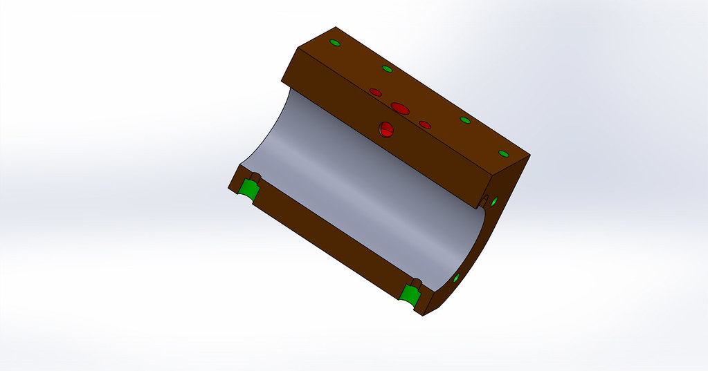 but I do complex shapes in my chosen path of professional expression. (I make bicycles frames) this is an investment cast seat lug 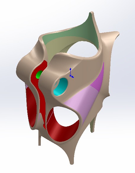 Then in 5 seconds I can drop the 3D part to the 2D drawing page. Spend some minutes adding dimensions. Print and go to the workshop. 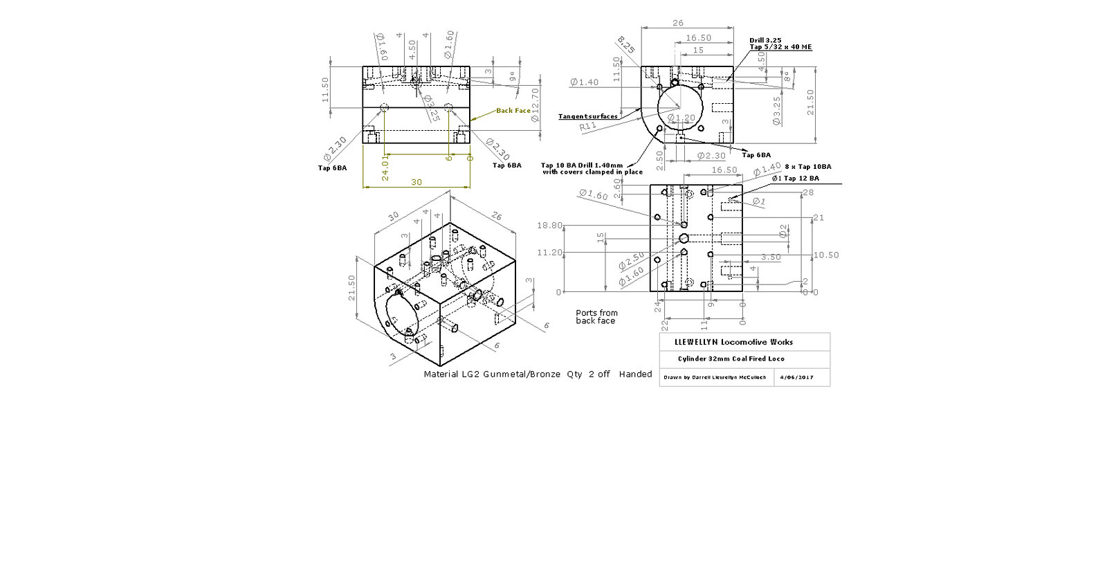 One can draw sketches any where on the 3D drawing and hide them from view, these might be used to check details or as aids in construction of complex parts and surface modelling. Print and go to the workshop. 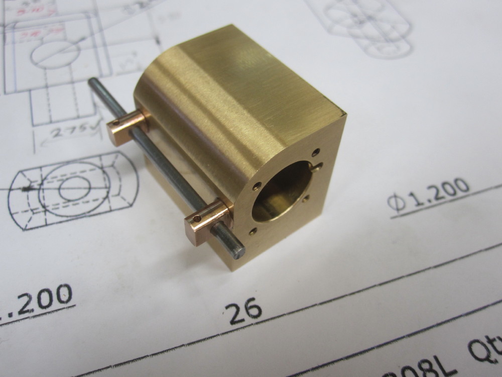 Note, these are for my use and not for publication or sale so I make no claims that my drawings meet any sort of professional drawing standard, but they are for my simple mind to comprehend and use in my hobby. However, the 3D model remains and it can be used later at any time by any one. Now the big, huge mega plus of 3D is (remember it takes next to no extra effort to create than just a 2D drawing) is that it can be used in assembly, a working and moving part assembly. This is the 32mm loco I am making with most of the parts hidden but for frames and motion as I sort the problems and redesign the original drawings. 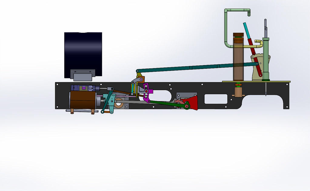 One can check all the clearances and holes line up, fits etc etc. Just like playing with Lego! If one finds a hiccup, then it is alter the original part, save and so it automatically updates the part, the part in the full assembly and the 2D drawing is also updated!!!!!!!!!!!!!!!!!!!!!!!!!!!!!!!!!!!!!YAY!!!!!!!!!!!!!!!!!!! If Martin Evans and his peers had this in their time then most of the whoops and $#^@*!!#%!!!!* ## would vanish. OK, However Douglas Adams still applies "A common mistake that people make when trying to design something completely foolproof is to underestimate the ingenuity of complete fools."also you could send the file (STL) by email to another country and get an investment cast part mailed back. :-) 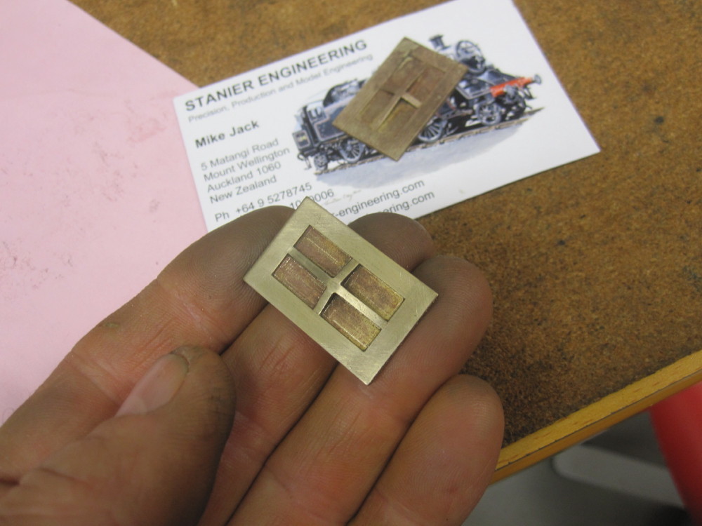 one day I want to make my masterpiece, #253 as delivered down Main st in 1921 to the Wooloongabba railyards that was across the road from the Gabba cricket ground. 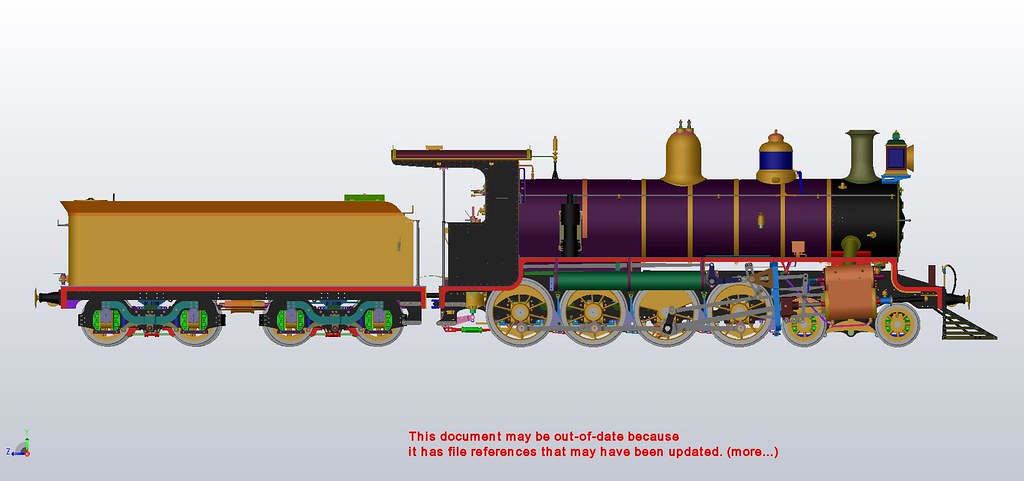 I make no claims of being a pro and meeting pro drafting standards, but I would never go back to 2D drafting via a keyboard or with the pencil. I do appreciate the traditional drafting skills in the drawing offices, but no where is the pencil used here but for sketches and notes on the printed drawings. The CAD tool is so marvelous in the second decade of the 21st century. If you want to use pencil and paper, or a 2D only CAD or chook scratchings on the back of an envelope then that is cool. Play as you want to play and lovely stuff can be made, ex: Cherry Hill's stuff is pencil work and it is wow. I can not part with 3D and I cannot part with DRO on my mill/drill. PS. I read in ME magazine some one moaning about the different colours used in 3D drawings, the colours can be changed in a second but they help one's mind and eye comprehend the assembly when it gets complicated. Later one can play with the colours and rendering to make a very realistic picture, but that has NO BENEFIT to the making of the part. Might be useful for marketing purposes but not worth the effort in my world, yet! |
|
|
|
Post by Roger on Dec 14, 2017 22:34:38 GMT
One big plus for 3D CAD/CAM is that there are no visualisation issues that you sometimes get with 2D Engineering Drawings. My SPEEDY plans by LBSC have some fundamental errors that make a nonsense of the part being described because the views are inconsistent. In particular the boiler drawing is wrong with regard to where the flanges are sectioned. That can't happen on 3D created Engineering Drawings. I spent hours puzzling over the complex casting of a compound Dodman Traction Engine's valve gear to get a handle on what it actually looked like in 3D. I've been reading Engineering drawings since I was a child, but some things are just mind bending when all you have is multiple section views to support the familiar ones.
Once something is 3D modelled, (and as Dazza says, it's just sketches and extrusions) you can spin it around on the screen, something I find really useful in the workshop when visualising machining operations. I only create Engineering Drawings for about half of the parts I make, the 3D model is enough to make it. I can point to any edge and get a length, or select any two features and find the X/Y/Z and shortest length between them.
I've completely eliminated any paper drawings from my build, I don't think I've printed even one! What's the point when you have a screen with the 3D model and any Engineering Drawings on hand in the workshop.
Maybe I'm a little unusual in this regard, but there was a time when we all used to print out datasheets, emails or other mundane things so we didn't lose them. These days, the only things I ever print out are dispatch labels and copy invoices you have to keep for the tax man. Everything else is entirely held on the computer, hence using the Cloud, multiple computers and Memory sticks to be certain I can never lose anything.
I'm sure this is all very alien to someone who's unfamiliar with Computers or CAD, and only works with printed drawings, but it's not rocket science. We're just using modern tools to make life much easier and our time more productive and less prone to error.
|
|
|
|
Post by Oily Rag on Dec 14, 2017 22:52:47 GMT
One big plus for 3D CAD/CAM is that there are no visualisation issues that you sometimes get with 2D Engineering Drawings. My SPEEDY plans by LBSC have some fundamental errors that make a nonsense of the part being described because the views are inconsistent. In particular the boiler drawing is wrong with regard to where the flanges are sectioned. That can't happen on 3D created Engineering Drawings. I spent hours puzzling over the complex casting of a compound Dodman Traction Engine's valve gear to get a handle on what it actually looked like in 3D. I've been reading Engineering drawings since I was a child, but some things are just mind bending when all you have is multiple section views to support the familiar ones. Once something is 3D modelled, (and as Dazza says, it's just sketches and extrusions) you can spin it around on the screen, something I find really useful in the workshop when visualising machining operations. I only create Engineering Drawings for about half of the parts I make, the 3D model is enough to make it. I can point to any edge and get a length, or select any two features and find the X/Y/Z and shortest length between them. I've completely eliminated any paper drawings from my build, I don't think I've printed even one! What's the point when you have a screen with the 3D model and any Engineering Drawings on hand in the workshop. Maybe I'm a little unusual in this regard, but there was a time when we all used to print out datasheets, emails or other mundane things so we didn't lose them. These days, the only things I ever print out are dispatch labels and copy invoices you have to keep for the tax man. Everything else is entirely held on the computer, hence using the Cloud, multiple computers and Memory sticks to be certain I can never lose anything. I'm sure this is all very alien to someone who's unfamiliar with Computers or CAD, and only works with printed drawings, but it's not rocket science. We're just using modern tools to make life much easier and our time more productive and less prone to error. Rodger, at this time I still need the paper drawing to take the to the workshop, as I am still set up for the Mark I cranium driven machinery and I make notes and alterations to them, which look like chook scratchings when I am done and then I go back to the 3D model and or 2D drawing sheet and add/alter update. However if there is a question, problem or some thing missing, I refer to the PC to confirm or alter etc. Then I move on. All this just in case some one else makes use of my efforts and it is good discipline for me as I have paid good gold coin for 5" loco drawings that left a lot to be desired. So I make an effort to lift my game. 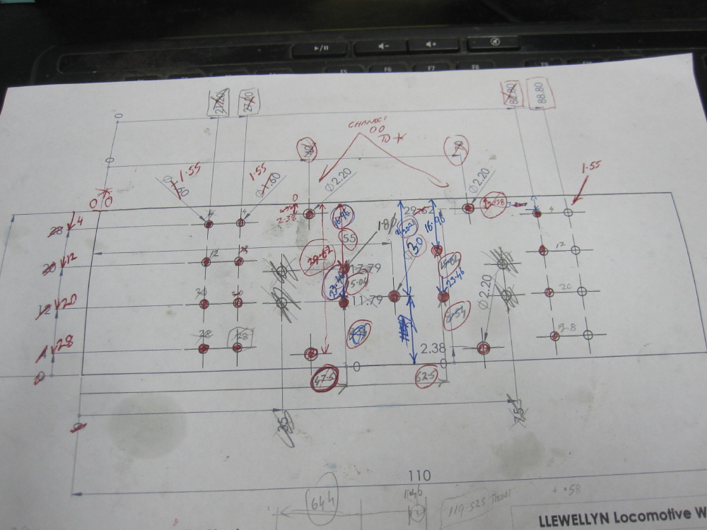 Now one does not need the 2D drawings archived, it is all there in the 3D parts and the assembly and these need to be archived and updated with care and a methodical approach or mistakes can be perpetuated, which is a moan I have with "paid for designs". |
|
|
|
Post by Roger on Dec 15, 2017 2:33:48 GMT
Rodger, at this time I still need the paper drawing to take the to the workshop, as I am still set up for the Mark I cranium driven machinery and I make notes and alterations to them, which look like chook scratchings when I am done and then I go back to the 3D model and or 2D drawing sheet and add/alter update. However if there is a question, problem or some thing missing, I refer to the PC to confirm or alter etc. Then I move on. All this just in case some one else makes use of my efforts and it is good discipline for me as I have paid good gold coin for 5" loco drawings that left a lot to be desired. So I make an effort to lift my game. Now one does not need the 2D drawings archived, it is all there in the 3D parts and the assembly and these need to be archived and updated with care and a methodical approach or mistakes can be perpetuated, which is a moan I have with "paid for designs". Hi Dazza, In the scenario you show, and using a DRO, I'd create the drawing from the 3D model and then add the dimensions in pretty much the same way you've done there. The only difference is that it's less prone to error since you aren't writing the dimension yourself. I think the only time I'd print that out would be if I was physically marking out the holes on the bench which is away from the computer display. In normal operation, I never mark out anything. The screen can be turned so that I can view it while working on the Lathe or the Mill. I can see why people like to have a paper drawing, I just wanted to point out that it's not something I do myself. |
|
|
|
Post by Oily Rag on Dec 15, 2017 2:54:11 GMT
Rodger, at this time I still need the paper drawing to take the to the workshop, as I am still set up for the Mark I cranium driven machinery and I make notes and alterations to them, which look like chook scratchings when I am done and then I go back to the 3D model and or 2D drawing sheet and add/alter update. However if there is a question, problem or some thing missing, I refer to the PC to confirm or alter etc. Then I move on. All this just in case some one else makes use of my efforts and it is good discipline for me as I have paid good gold coin for 5" loco drawings that left a lot to be desired. So I make an effort to lift my game. Now one does not need the 2D drawings archived, it is all there in the 3D parts and the assembly and these need to be archived and updated with care and a methodical approach or mistakes can be perpetuated, which is a moan I have with "paid for designs". Hi Dazza, In the scenario you show, and using a DRO, I'd create the drawing from the 3D model and then add the dimensions in pretty much the same way you've done there. The only difference is that it's less prone to error since you aren't writing the dimension yourself. I think the only time I'd print that out would be if I was physically marking out the holes on the bench which is away from the computer display. In normal operation, I never mark out anything. The screen can be turned so that I can view it while working on the Lathe or the Mill. I can see why people like to have a paper drawing, I just wanted to point out that it's not something I do myself. Interesting thought. I like the paper next to me, rather than have a PC running all the time. I like the paper to make notes on, scribble down the cuts, progress and remaining, notes to add to update or alter the 3D and 2D drawings. For example I change the location of the origin on a buffer beam. I always have a paper to scribble on. Not sure if I can have the PC running while I am in the workshop. Just come to mind, when I am doing a lot of drilling I do like the paper next to me as I mark off the holes and the locations as I go along. Maybe because I am dim and slow I have to do that. Maybe as the days go by I may alter my method. All very interesting. |
|
|
|
Post by Roger on Dec 15, 2017 3:36:27 GMT
Interesting thought. I like the paper next to me, rather than have a PC running all the time. I like the paper to make notes on, scribble down the cuts, progress and remaining, notes to add to update or alter the 3D and 2D drawings. For example I change the location of the origin on a buffer beam. I always have a paper to scribble on. Not sure if I can have the PC running while I am in the workshop. Just come to mind, when I am doing a lot of drilling I do like the paper next to me as I mark off the holes and the locations as I go along. Maybe because I am dim and slow I have to that. Maybe as the days go by I may alter my method. All very interesting. Hi Dazza, It certainly is interesting to see how others work and why that suits them. I organise my jobs into folders and sub-folders so you might have Steam Engines/SPEEDY/Cab/Bunker and cab beading details for the part I'm machining. Everything required to make that specific part is contained in the folder, including a 'notes on...' text file that has any information I'll need if I run the job again. If there is separate tooling, or inverted machining operations, those are again sub-folders so that the operations are kept separate. As you can imagine, there can be 20 or more files in some of these part folders because the G-Code is in there too. Even things like a custom shaped washer will have its own folder with 3D model if nothing else. I've found over time that one physical part per root folder is the best way to keep the files in some kind of order. Chaos is always just around the corner if you don't! I also put the photos I take of the setup and different machining stages in the folder too. Again, this is helpful if you need to come back and repeat the operation later. I have a terrible memory, so being strict about these methods keeps me out of trouble. As far as comments on the drawings themselves, I sometimes add text notes to them in much the same way that you do on paper. So in fact, I'm doing pretty much all that you're doing with your drawing, although I prefer a separate Notes file because that can then be as large as I like. On complex items I do a step by step planned machining order with the names of the files. I've modified the Post Processor so that it output the tool diameter at the head of the program so there's a sanity check before you start machining. Picking the wrong cutter is such an easy mistake to make. |
|
|
|
Post by Oily Rag on Dec 15, 2017 20:57:18 GMT
Snipped from Rodger's post
"I also put the photos I take of the setup and different machining stages in the folder too. Again, this is helpful if you need to come back and repeat the operation later. I have a terrible memory, so being strict about these methods keeps me out of trouble."
Now that is something I should do. I need to sit down and do this before I go to far down the line with this project , even though this is my simple loco, the desire is to sort and create the process for when I do more complex loco projects.
The C17 and then a QR Beyer Garratt in 5"
|
|
jools
E-xcellent poster
Posts: 200
|
Post by jools on Dec 15, 2017 22:56:15 GMT
Each to their own as they say, but what are you basing your 3D designs of existing components on ?
|
|


 )
)


