Post by springcrocus on Jun 7, 2016 21:52:00 GMT
A week or two back I tossed out a suggestion for anyone to describe, in detail, between-centres boring but it appears that nobody wants to pick up the gauntlet. A pity, really, because I'm sure there are many people out there far more knowledgeable than me who could do this subject justice. Between-centres boring is often referred to but seldom expanded on and is not a procedure that anyone new to model engineering is likely to understand or even know how to perform. I have just finished making the first of the two between-centres boring bars that I need to machine my cylinders and will describe how I made it and how I will use it.
First, though, I thought I'd try to explain why I want to use between-centres boring bars at all. It seems easy enough to be able to load locomotive cylinders (or anything with a long bore) to a four-jaw chuck or a face plate and machine the bores using a boring bar in the lathe tool post. The problem that I see with this method is it can introduce a taper to the bore of the cylinder because of misalignment of the headstock or twisting of the bedway and the only way to ensure a parallel bore is to use a reamer or similar tool in the tailstock to size the bore, quite an expensive solution in the larger sizes and still no guarantee of a parallel bore if the reamer is out of line and cuts at the back. Another problem is that the valve bore is way off the centre of mass of the casting and swinging this lump around in a four-jaw chuck would have the lathe oscillating like a rocking chair. It could be mounted on a large faceplate with a balancing weight but, since I don't have one, that option is not open to me.
Cylinder bores could be machined successfully using a boring head in a vertical mill but it seems that the majority of our hobby-sized machines, my own included, do not have enough travel in the quill to complete the operation. Winding the table up and down (z-axis) on a turret mill, where the milling head remains static and the knee moves, would work well enough but on our smaller hobby mills adjustment is often made by winding the head up and down the column and this introduces it's own set of problems. In fact, it is impossible in round-column mills to stop side-to-side movement and even dovetailed vertical columns need to be quite closely adjusted on the gib strips to prevent any wander.
When it comes to parallel bores, between-centres boring in the lathe cannot be beaten. In fact, if you think about it, it is impossible to introduce a taper to the bore, other than for tool wear in a single pass. The reason for this is because it is a single-point cutter and the tip of the cutting tool is following a fixed circular path which will not deviate (unless the operator changes something, such as tightening the tailstock centre during the cut which may cause the bar to move sideways). The only inaccuracy that can occur is in the alignment of the bore or size of the bore, both of which are the responsibility of the operator during initial setup. However, a parallel bore is guaranteed!
It is called between-centres boring but, in fact, the boring bar doesn't actually need to be between centres. The only requirement is that both ends of the tool need to be supported to ensure that there is no lateral movement. The advantage of using the bar between centres is repeatability because, once the size is set, it can then be removed from the machine and the next workpiece set up. Then the boring bar can be reloaded and machining of the next item continue. It is usual, therefore, to use a centre in the headstock and drive the bar using a driving dog fixed to the bar and driven by a catch-plate. However, to ensure good repeatability, it is normally neccessary to lock the tailstock in place and adjust the pressure to the same setting each time.
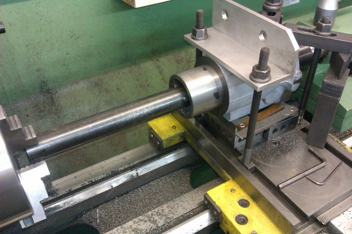
If there is only one workpiece that needs machining, then it is possible to hold the driven end directly in a three-jaw chuck and with a live centre in the tailstock supporting the other end. It doesn't even need to be running perfectly true at either end because this is not what controls the diameter of the cut, it just needs to be held rigid so that the tip of the cutter rotates around a fixed circle in space. All adjustment of size is made by varying the height of the tool tip above the centreline of the boring bar.
Measuring the bore, however, is a different matter and this is where being able to remove the boring bar and return it accurately pays off. If the bar is designed well enough, then it shouldn't need to be removed from the machine as it would be possible to use digital or vernier calipers to measure one end of the bore. There is no need to measure both ends because the bore WILL be parallel. However, if greater accuracy is required then removal of the boring bar would be an asset so that a bore gauge or plug gauge could be used instead.
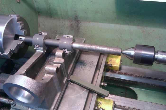
This first boring bar that I have made is designed to finish the valve bore at 1.1/4" diameter and is made from 25mm diameter mild steel and is a little longer than twice the length of the cylinder. The tailstock end has been centre-drilled with a No3 Slocombe and I intend to hold the bar in the 3-jaw chuck so have turned a shoulder to rest against the chuck jaws.

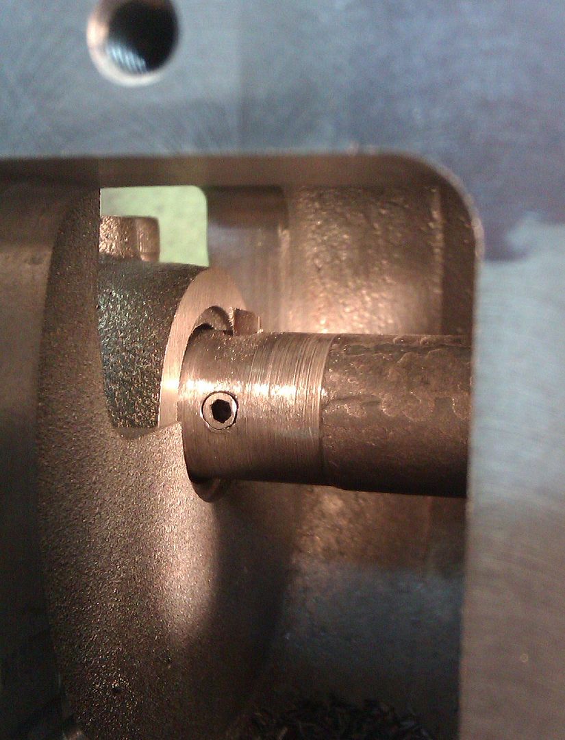
The cutter is an old No.3 centre drill suitably ground and can be adjusted to produce a bore in the range 1.1/16" to about 1.1/2". Adjustment is with an M6 grub screw beneath the cutter and side-locking is provided by an M5 grub screw.

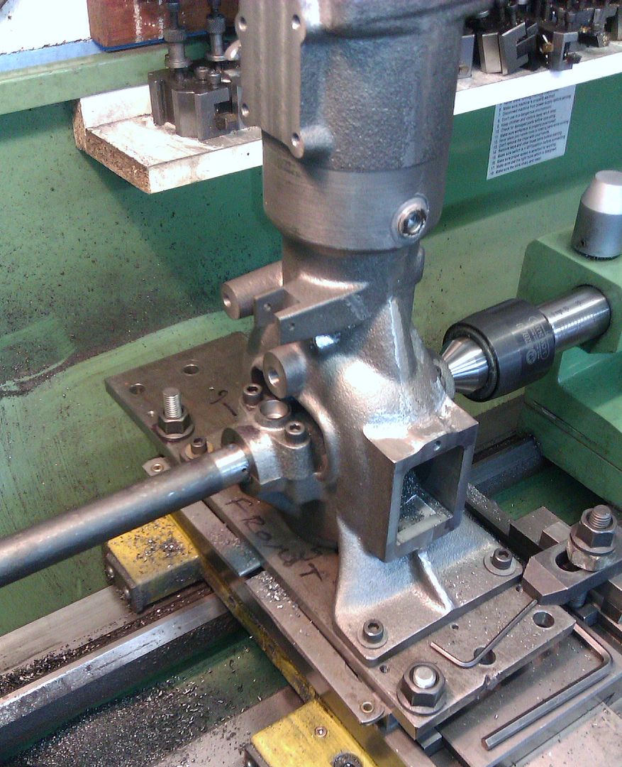
I have also made a larger boring bar to finish the piston bore at 1.3/4" and have made this from some 1.1/8" material. Because I have added locating dowels to the backplate, I can finish the first bore on both cylinders before adjusting the slides and finishing the second bore. this will maintain the spacing between the two bores and they will also be perfectly parallel to each other.

The actual work on the cylinders will be covered in my Britannia diary.
Sorry, lots of waffle and not many pictures on this one but I hope someone finds it interesting.
Steve
First, though, I thought I'd try to explain why I want to use between-centres boring bars at all. It seems easy enough to be able to load locomotive cylinders (or anything with a long bore) to a four-jaw chuck or a face plate and machine the bores using a boring bar in the lathe tool post. The problem that I see with this method is it can introduce a taper to the bore of the cylinder because of misalignment of the headstock or twisting of the bedway and the only way to ensure a parallel bore is to use a reamer or similar tool in the tailstock to size the bore, quite an expensive solution in the larger sizes and still no guarantee of a parallel bore if the reamer is out of line and cuts at the back. Another problem is that the valve bore is way off the centre of mass of the casting and swinging this lump around in a four-jaw chuck would have the lathe oscillating like a rocking chair. It could be mounted on a large faceplate with a balancing weight but, since I don't have one, that option is not open to me.
Cylinder bores could be machined successfully using a boring head in a vertical mill but it seems that the majority of our hobby-sized machines, my own included, do not have enough travel in the quill to complete the operation. Winding the table up and down (z-axis) on a turret mill, where the milling head remains static and the knee moves, would work well enough but on our smaller hobby mills adjustment is often made by winding the head up and down the column and this introduces it's own set of problems. In fact, it is impossible in round-column mills to stop side-to-side movement and even dovetailed vertical columns need to be quite closely adjusted on the gib strips to prevent any wander.
When it comes to parallel bores, between-centres boring in the lathe cannot be beaten. In fact, if you think about it, it is impossible to introduce a taper to the bore, other than for tool wear in a single pass. The reason for this is because it is a single-point cutter and the tip of the cutting tool is following a fixed circular path which will not deviate (unless the operator changes something, such as tightening the tailstock centre during the cut which may cause the bar to move sideways). The only inaccuracy that can occur is in the alignment of the bore or size of the bore, both of which are the responsibility of the operator during initial setup. However, a parallel bore is guaranteed!
It is called between-centres boring but, in fact, the boring bar doesn't actually need to be between centres. The only requirement is that both ends of the tool need to be supported to ensure that there is no lateral movement. The advantage of using the bar between centres is repeatability because, once the size is set, it can then be removed from the machine and the next workpiece set up. Then the boring bar can be reloaded and machining of the next item continue. It is usual, therefore, to use a centre in the headstock and drive the bar using a driving dog fixed to the bar and driven by a catch-plate. However, to ensure good repeatability, it is normally neccessary to lock the tailstock in place and adjust the pressure to the same setting each time.
If there is only one workpiece that needs machining, then it is possible to hold the driven end directly in a three-jaw chuck and with a live centre in the tailstock supporting the other end. It doesn't even need to be running perfectly true at either end because this is not what controls the diameter of the cut, it just needs to be held rigid so that the tip of the cutter rotates around a fixed circle in space. All adjustment of size is made by varying the height of the tool tip above the centreline of the boring bar.
Measuring the bore, however, is a different matter and this is where being able to remove the boring bar and return it accurately pays off. If the bar is designed well enough, then it shouldn't need to be removed from the machine as it would be possible to use digital or vernier calipers to measure one end of the bore. There is no need to measure both ends because the bore WILL be parallel. However, if greater accuracy is required then removal of the boring bar would be an asset so that a bore gauge or plug gauge could be used instead.
This first boring bar that I have made is designed to finish the valve bore at 1.1/4" diameter and is made from 25mm diameter mild steel and is a little longer than twice the length of the cylinder. The tailstock end has been centre-drilled with a No3 Slocombe and I intend to hold the bar in the 3-jaw chuck so have turned a shoulder to rest against the chuck jaws.
The cutter is an old No.3 centre drill suitably ground and can be adjusted to produce a bore in the range 1.1/16" to about 1.1/2". Adjustment is with an M6 grub screw beneath the cutter and side-locking is provided by an M5 grub screw.
I have also made a larger boring bar to finish the piston bore at 1.3/4" and have made this from some 1.1/8" material. Because I have added locating dowels to the backplate, I can finish the first bore on both cylinders before adjusting the slides and finishing the second bore. this will maintain the spacing between the two bores and they will also be perfectly parallel to each other.
The actual work on the cylinders will be covered in my Britannia diary.
Sorry, lots of waffle and not many pictures on this one but I hope someone finds it interesting.
Steve