johnthepump
Part of the e-furniture
 Building 7 1/4"G Edward Thomas
Posts: 493 
|
Post by johnthepump on Nov 27, 2018 22:39:50 GMT
The Evening went well all the seized parts pressed out easily with no heat required. The parts have now gone off to another members workshop so he can clean them up and return them to site next Tuesday morning.  27.11.2018 27.11.2018 by John The Pump, on Flickr Back to model engineering tomorrow evening. John. |
|
johnthepump
Part of the e-furniture
Building 7 1/4"G Edward Thomas
Posts: 493
|
Post by johnthepump on Dec 23, 2018 12:51:19 GMT
I bought 2 Dixon toolholder storage racks from Model Engineers Laser a few weeks back and I asked for them to be a kits and I would Tig them up. I had bought one back in 2016 and found a couple of tool holders were a tight fit. I would seem there are slight differences depending on the maker. I decided to machine 5 thou. off each lug before welding them up, I had to file the first one I bought. 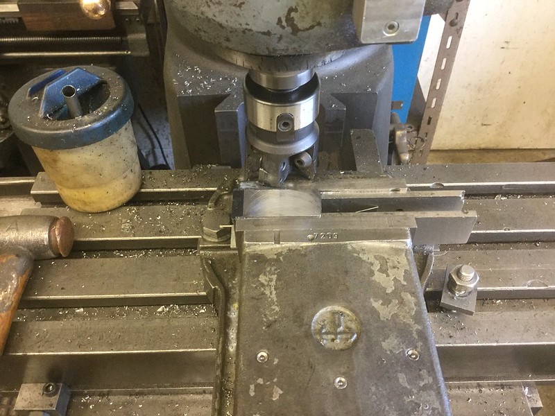 29.11.2018 29.11.2018 by John The Pump, on Flickr 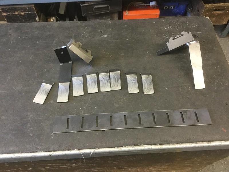 29.11.2018 29.11.2018 by John The Pump, on Flickr |
|
johnthepump
Part of the e-furniture
Building 7 1/4"G Edward Thomas
Posts: 493
|
Post by johnthepump on Dec 23, 2018 13:18:43 GMT
A little more progress with the Loco, Wilf had started on the first stage of making the first of the piston glands the other week, I finished it off and then made the second. It was then onto the Micromill to machine the gland shape and drill the holes. 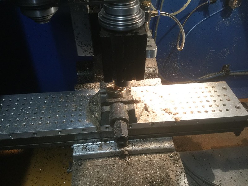 20.12.2018 20.12.2018 by John The Pump, on Flickr 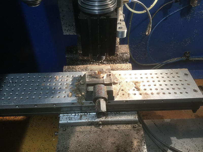 20.12.2018 20.12.2018 by John The Pump, on Flickr  20.12.2018 20.12.2018 by John The Pump, on Flickr 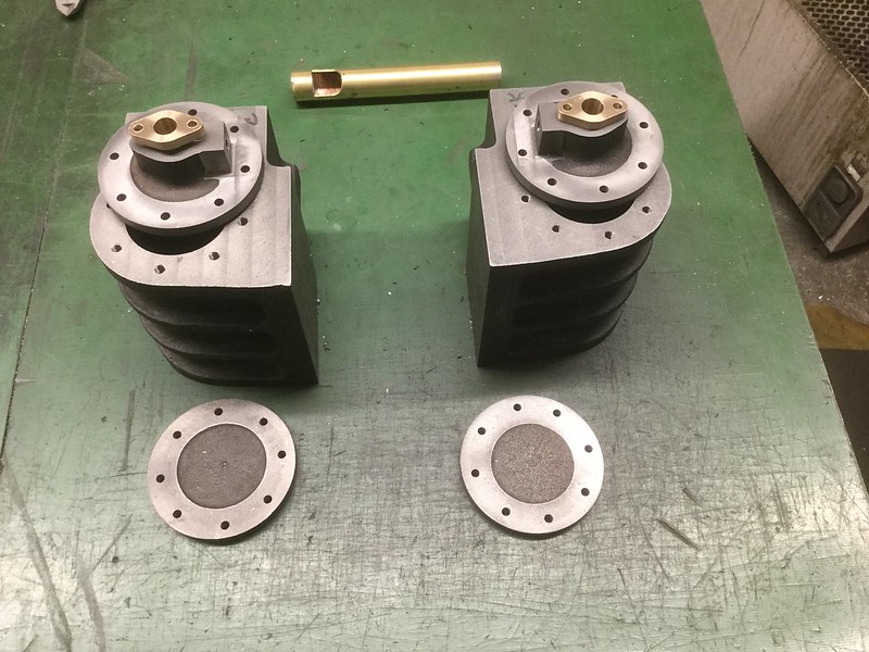 20.12.2018 20.12.2018 by John The Pump, on Flickr The Whistle behind the cylinders, was from the club and it didn't sound at all well, so I have stripped it down re-machined it and silver soldered it back together again and on air it sound much better, once back on the engine and under steam will be the real test. Hope you all have a Merry Christmas and a Happy New Year. John. |
|
uuu
Elder Statesman
 your message here...
Posts: 2,807
|
Post by uuu on Dec 24, 2018 12:23:21 GMT
I misread the drawing and started making the first one too long, so had to shorten it. Perhaps the second one has the same issue, as it seems to be sticking out a bit.
Wilf
|
|
johnthepump
Part of the e-furniture
Building 7 1/4"G Edward Thomas
Posts: 493
|
Post by johnthepump on Jan 4, 2019 23:24:29 GMT
Once again I have been side tracked from the loco build. This time it was to make a filter foot valve for a small impeller pump, which we are going to use to pump out the underfloor flooded pipe trenches at the Men in Sheds project that I am involved in.  03.01.2019 03.01.2019 by John The Pump, on Flickr Keep making swarf, John. |
|
johnthepump
Part of the e-furniture
Building 7 1/4"G Edward Thomas
Posts: 493
|
Post by johnthepump on Jan 15, 2019 9:14:18 GMT
The distractions continue this time there was a need for a spanner to undo some 1 1/2" Whitworth nuts on one of the Rustons on the Men in Sheds project that I'm involved with. I had an old open end spanner which would have been the correct size, had I not ground it out to fit another job 20 years or so ago. Grinding out spanner is not something I would normally do, but I was tasked with replacing an oil seal on an engine in a standby generator on a tomato nursery. The engine was a Rolls Royce C type and the spanner was ground out a little to do the job. We did try the spanner the Ruston with a little packing in the jaw but it would not shift the nuts. So the team started talking about flogging spanner and well you know what talk does not a lot. So last Wednesday evening the Pumphouse team set to and marked out a piece of steel strip 100 x 12 mm about 500 long with the out of the hex at 15 deg. they drilled a small hole at each corner and one central hole for mounting onto the rotary table. I didn't get back to it until yesterday but it milled out a treat and so this morning its is going to be tried out. This is 2.41" accross flats.  14.01.2019 14.01.2019 by John The Pump, on Flickr 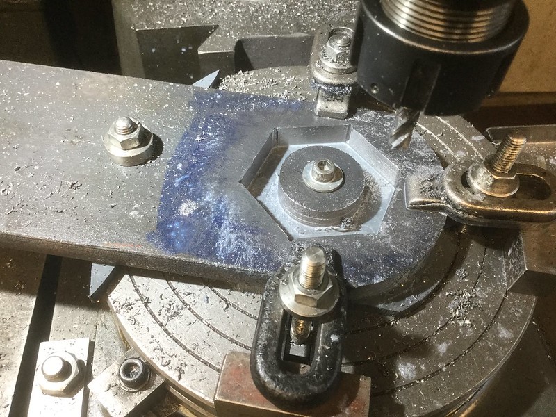 14.01.2019 14.01.2019 by John The Pump, on Flickr  14.01.2019 14.01.2019 by John The Pump, on Flickr John. |
|
johnthepump
Part of the e-furniture
Building 7 1/4"G Edward Thomas
Posts: 493
|
Post by johnthepump on Jan 15, 2019 17:21:12 GMT
Just a quick update on the flogging spanner from this mornings post. It did the job with the aid of a lump hammer ( I have arm ache as a result) the nuts on the top bolt were undone first to see how things went. Because of the limited space around the lower nuts, the spanner had to be shortened somewhat, on site the only choice was the hacksaw 100 x 12 mm, no wonder the arm aches. 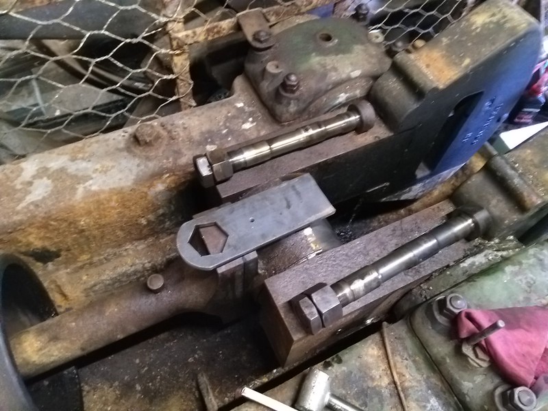 IMG_20190115_122111 IMG_20190115_122111 by John The Pump, on Flickr John. |
|
johnthepump
Part of the e-furniture
Building 7 1/4"G Edward Thomas
Posts: 493
|
Post by johnthepump on Jan 15, 2019 17:39:20 GMT
A little job earlier in the week. I was asked by a friend if I could make some nesting heart shapes in 6 mm aluminium. They are to do with making Rosettes which are awarded at horse shows which this ladies friend make, their idea as valentines day is next month is to make some that are heart shaped. How they are used to make the rosettes I have no idea. 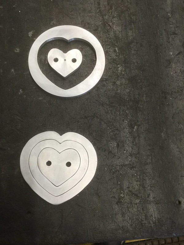 12.01.2019 12.01.2019 by John The Pump, on Flickr The picture shows the nest plus the left over pieces from making the middle heart shape. John. |
|
|
|
Post by runner42 on Jan 16, 2019 0:38:51 GMT
Hi John,
I notice in the photo of your micro mill that you have affixed an aluminium plate with lots of fixing holes to increase the number of clamping positions, however what is the purpose of the holes drilled in the side?
Brian
|
|
johnthepump
Part of the e-furniture
Building 7 1/4"G Edward Thomas
Posts: 493
|
Post by johnthepump on Jan 16, 2019 9:44:37 GMT
Hi John, I notice in the photo of your micro mill that you have affixed an aluminium plate with lots of fixing holes to increase the number of clamping positions, however what is the purpose of the holes drilled in the side? Brian Hi Brian, The Sub plate was an optional extra for the MicroMill the holes are tapped 6 mm and spaced at 12 mm. I put in the holes along the front edge to accommodate edge location on some of the work I do. The machine also came with 4 cam locks, which are basically an 6 mm allen screw with an eccentric head that locates in a hexagon washer, so turning the screw a sideways clamping action is achieved these are very useful to hold thin materials down. 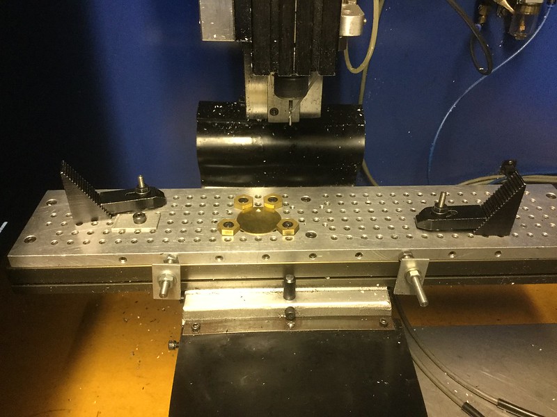 17.11.2016 17.11.2016 by John The Pump, on Flickr I also have 4th axis on this machine which has come in handy at times. 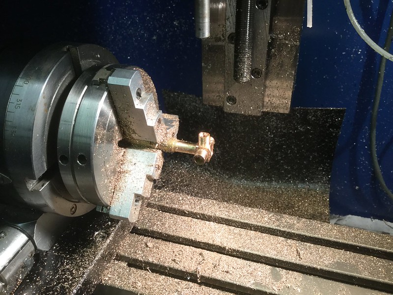 30.03.16 30.03.16 by John The Pump, on Flickr Regards John. |
|
|
|
Post by runner42 on Jan 16, 2019 21:37:21 GMT
Hi John.
that's a very useful addition and I am interested in making a similar plate for my micro mill. I would be interested to see other photos of set ups that you have used in the past, just to amplify the versatility of it's use, but only at your convenience.
Brian
|
|
johnthepump
Part of the e-furniture
Building 7 1/4"G Edward Thomas
Posts: 493
|
Post by johnthepump on Jan 21, 2019 12:25:34 GMT
Hi John. that's a very useful addition and I am interested in making a similar plate for my micro mill. I would be interested to see other photos of set ups that you have used in the past, just to amplify the versatility of it's use, but only at your convenience. Brian Hi Brian, Here are a few more photos of set ups on the MicroMill. 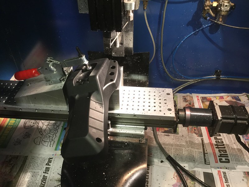 Case back Case back by John The Pump, on Flickr The mount is an aluminium block cut at an angle to present the case so that the 2 socket holes can be machined the other half of the block holds the clamp, there are register pins that locate the case back in place. This little job came up now and then but it is only a few at a time. 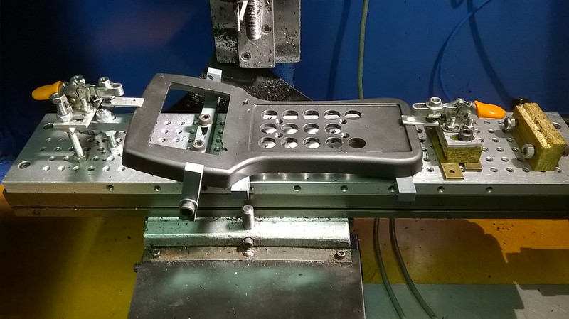 WP_20150124_002(1) WP_20150124_002(1) by John The Pump, on Flickr This is a case front set up, the front is an old one that got damaged I use it for set and checking, there is always the dread of pressing the start button! once again there was only a few of these each time. that's why I took the photos it helped with set ups. 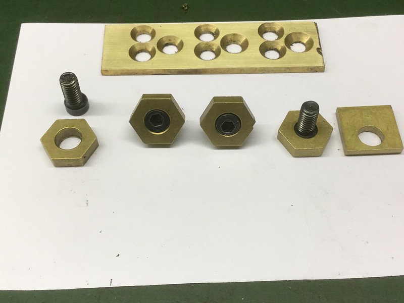 20.01.2019 20.01.2019 by John The Pump, on Flickr Here is a view of the cam clamps these are useful for thin jobs.  DSCN1672 DSCN1672 by John The Pump, on Flickr This shows a 4th axis job, it is the outside case of an alarm clock, a one off I was asked to do , it was a pre-production sample. I hope these few set ups give you some ideas for your own jobs. Regards John. |
|
johnthepump
Part of the e-furniture
Building 7 1/4"G Edward Thomas
Posts: 493
|
Post by johnthepump on Feb 4, 2019 14:25:11 GMT
Once again my Loco has taken a back seat, although I did manage to make a few more cylinder cover studs ( first op ). This weeks distraction was to make a replacement dynamo jacking screw 7/8" whitworth, this is to replace one that was totally rusted and ended up being cut off to remove it. the dynamo in question is plated 250V DC 108.8A 25KW at 1500RPM and is one of two dynamos driven by a Ruston 9XHR 66HP. 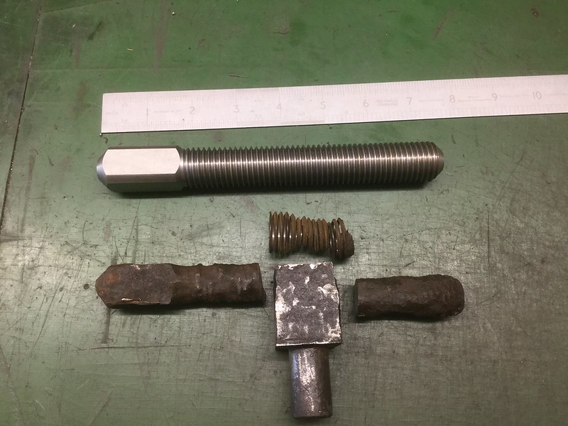 04.02.2019 04.02.2019 by John The Pump, on Flickr The section of the old screw was successfully bored out of the other part and as this is a conservation/ restoration project this part will be reused. John. |
|
uuu
Elder Statesman
your message here...
Posts: 2,807
|
Post by uuu on May 11, 2019 5:48:52 GMT
I thought I'd post an update - and try to poke John into posting some photos:
The last couple of Wednesday evenings we've been visited by a chap building a Stirling single. The one with inside cylinders. We had machined his drivers for him some time ago. He has the chassis erected, and was trying to time the valves, but getting nowhere. First we did a check on the eccentrics - they didn't look at all right, pointing in all the wrong directions, and with the arms connected the wrong way round. So we had the axle out, and onto the surface table, so we could measure everything with a height gauge. Having set them up to the drawings, we then hit the next problem, which was in the mind rather than in metal. He couldn't figure out how the valve travel could be less than the throw of the eccentric. He took a lot of persuading - we had to feed all the dimensions into a simulation program and demonstrate that it all worked. I suspect he'll be back.
Meanwhile, we've been machining John's smokebox door. Another visitor had gifted a vaguely suitable casting, so, having checked it would all work out, we set about making cast iron swarf. If John can post a picture, it will avoid the need for the thousand words of explanation of the jig to get the curve right.
Wilf
|
|
uuu
Elder Statesman
your message here...
Posts: 2,807
|
Post by uuu on May 16, 2019 19:24:32 GMT
We have pictures:  SmokeboxDoor3 SmokeboxDoor3 by Wilf, on Flickr This first one shows the method: - The topslide handle and drivescrew are removed, so it can slide freely.
- A rigid bar, red in this case, is mounted in the toolpost projecting to the right.
- A lower bar , it's left hand end pivots on a pedestal attached to the carriage. On the Myford, there's a threaded hole to mount the fixed steady, which is ideal for this. The length of this bar, between the pivot holes, is the radius of the curve to be machined.
- The right hand end of the lower bar attaches with a pivot to the rigid red bar
- When the lower bar is parallel to the bed, the tip of the tool is arranged to be at the centre of the work.
- As the cross slide is withdrawn backwards, the lower bar swings round, pushing the red bar, and therefore the topslide, towards the chuck
- Forward movement of the cross slide moves the topslide in the reverse arc.
- The whole assembly moves with the carriage, so feed can be applied.
- After the first few cuts we realised the leverage of the red bar was sufficient to swivel the toolpost a bit, so the brace was added in the middle.
 SmokeboxDoor1 SmokeboxDoor1 by Wilf, on Flickr Second photo shows the start of another cut.  SmokeboxDoor4 SmokeboxDoor4 by Wilf, on Flickr Final photo shows the finished item - last night we machined the button in the centre - it has a domed top, and undercut. Both these were turned with form tools. Wilf |
|
|
|
Post by simplyloco on May 16, 2019 20:39:28 GMT
Very nice, but I can't tell you what the last picture reminds me of!  John |
|
johnthepump
Part of the e-furniture
Building 7 1/4"G Edward Thomas
Posts: 493
|
Post by johnthepump on May 16, 2019 21:30:43 GMT
Thanks must go to Wilf for all his time on this smoke box door project. The casting I was given by another club member was a much larger diameter and curvature than was required for Edward Thomas. The curvature required was 15" radius, after checking whether there would be sufficient thickness left. a start was made to machine the edge to diameter and the closing face on the back of the door, this was all done on the 5" LeBlonde lathe. The job was then transferred to the Myford to do the front, in the second photo a 6 mm stainless steel spacer plate can be seen behind the casting so that front was just in front of the chuck jaws allowing the face to be machined all over. The final few cuts were made using power feed on the cross slide and this gave a superior finish over the previous cuts, form tools were ground up to turn the door knob in the centre of the door out of the chucking piece of the casting.
We now intend to get back to machining the cylinders.
John.
|
|
johnthepump
Part of the e-furniture
Building 7 1/4"G Edward Thomas
Posts: 493
|
Post by johnthepump on May 17, 2019 8:04:29 GMT
Another job done recently, was to make 3 new handwheels for a club engine. As it happened the square hole for each was a different size 1/8", 5/32", and 3/16". Because the centre boss was thicker than the rest of the handwheel the 1.5 mm cutter I had used was not long enough to do the square holes. At our Loco Rally in April last year Roger (1501) was one of our mainland visitors and he had given me some of those PCB burrs to try. now I had a job needing a long cutter, so it was time to give one ago, a 1/16" dia. is shown in the photo. I was very pleased with the result, so thank you Roger. John  20.03.2019 20.03.2019 by John The Pump, on Flickr |
|
JonL
Elder Statesman
WWSME (Wiltshire)
Posts: 2,906
|
Post by JonL on May 17, 2019 11:30:42 GMT
Both the smokebox and the handwheel look fantastic. I've just sat here waving my hands in the air and mumbling to myself trying to work out how the radius cutter worked, until it clicked! I had confused myself into thinking the cutting wasn't being carried out by the saddle, all mades sense now. Very elegant.
|
|
johnthepump
Part of the e-furniture
Building 7 1/4"G Edward Thomas
Posts: 493
|
Post by johnthepump on Sept 24, 2019 12:32:04 GMT
This is my first post since May. In the Photo below the rule there are 2 bolts the one on the right is the replacement that I made yesterday and it may not look much, just a small part to repair a club loco. But a giant step in my recovery.  23.09.2019 23.09.2019 by John The Pump, on Flickr On the 3rd of June I went for a Transperineal prostrate biopies, by midnight my wife was phoning for an ambulance, as I was fitting and not at all well. I spent the next six weeks in hospital while they tried to cure the infection. Two nights after discharge I was in an ambulance going back to hospital with oxygen with difficulty in breathing due fluid on the lungs. I was discharge the following week after they had reduced the body fluid. 19 litres in all I was at one time swollen up all over. recovery has been very slow, I needed a zimmer frame to get around for the first week or two, them a walking stick. Apart from the swelling I lost a lot of weight and muscle during my hospital stay. I'm slowly getting better and the progress can be seen each week, The one thing that is going to get any better is the loss of most of the vision in my right eye. It would seem this was down to the infection and lack of eating. The first time I went in my workshop was disappointing I could not see the dials on the machines and wondered if that was the end of model engineering as far as I was concerned. However the brain is wonderful and it has slowly compensated and now I can see the dials, although not easy I can make things, may many things follow this little bolt. John. |
|


