johnthepump
Part of the e-furniture
 Building 7 1/4"G Edward Thomas
Posts: 493 
|
Post by johnthepump on Oct 12, 2016 9:13:17 GMT
Further progress on the expansion links, I have now made one in the other hand in PVC. These trial pieces I was getting ready to show to the member when he turned up last evening, but he cancelled for some reason, but I will catch up with him up at the club this morning. We did however set up machine the first end of the water jetted blanks. John. 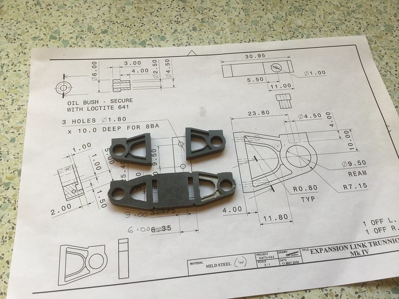 12.10.2016 12.10.2016 by John The Pump, on Flickr |
|
uuu
Elder Statesman
 your message here...
Posts: 2,807
|
Post by uuu on Oct 12, 2016 18:06:24 GMT
Before I set off for the Pumphouse - where I promise I'm not taking anything along to distract work on the loco - I thought I'd post pictures of the swarf guard John made for my lathe. From the local pub kitchen steel. Here's a picture showing the problem area - these vents are upward facing:  And here's a little skirt which shields them:  And here's the motor in place:  Many thanks to John for taking time out to do this. Wilf |
|
johnthepump
Part of the e-furniture
Building 7 1/4"G Edward Thomas
Posts: 493
|
Post by johnthepump on Oct 13, 2016 10:13:51 GMT
This Wednesday evening we were able to get on with my loco. So having worked out last time that stroke had been shortened by 0.100" to allow for the lack of length in the cylinder castings we set about cleaning up the ends coming to a final length of 3.930". The next job will be to work out the position of the mounting holes and get them drilled into the frames, this will allow for the horns to be riveted in place and the angle iron to be riveted along the length of the frames. After that the frames can be reassembled. John 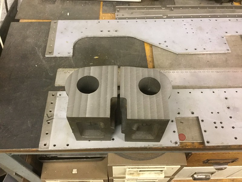 12.10.2016 12.10.2016 by John The Pump, on Flickr |
|
uuu
Elder Statesman
your message here...
Posts: 2,807
|
Post by uuu on Oct 20, 2016 12:40:47 GMT
Yesterday evening we started off by comparing the shape of these cylinders with the ones on the drawings. We wanted to see if there were any restrictions on the position of the bores, and plot some holes for mounting to the frames. John has drawn both shapes out in CAD, and after some discussion we became happy that the mounting and valve faces on John's cylinders would allow the same bore position. So we set to and started to cut:  Then we hit a snag. The boring head has two positions for the tool. Having run out of movement on the inner position, we moved the tool to the outer one, only to find that it was too far over to go down the bore. We concluded that the head must originally have had an additional tool holder, with intermediate holes. So off to the pub. Wilf |
|
|
|
Post by Deleted on Oct 20, 2016 18:17:50 GMT
Thanks for sharing Wilf, I'm taking notes...  Pete |
|
johnthepump
Part of the e-furniture
Building 7 1/4"G Edward Thomas
Posts: 493
|
Post by johnthepump on Oct 20, 2016 20:53:18 GMT
Tuesday evening I set up my MicroMill to machine the profile the second expansion link bracket for one of the Tuesday gang members 5"G Ivatt. The first one was machined last week and was brought back this week fitted to its mounting. John. 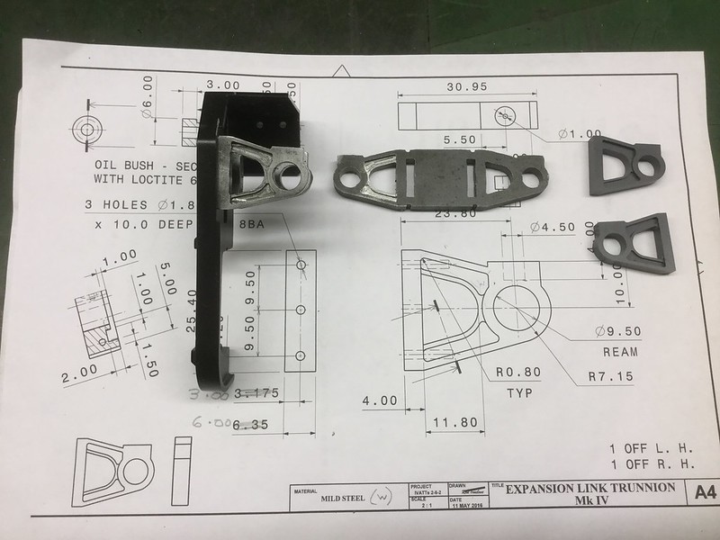 19.10.2016 19.10.2016 by John The Pump, on Flickr |
|
johnthepump
Part of the e-furniture
Building 7 1/4"G Edward Thomas
Posts: 493
|
Post by johnthepump on Oct 20, 2016 21:58:02 GMT
As Wilf pointed out earlier today, last evening we started on the bores of the cylinders the idea was to clean up the the cast hole on the mill, then set the cylinders up in the lathe and finish with a boring bar between centres. Our first problem was with the Elliott boring head which I had been giving by a club member being surplus to his requirement. Running out of adjustment in the first hole, moving the cutter the second hole it became clear that with the adjustment set back to minimum the cutter would not fit in the bore. We came to the conclusion that the boring head must have had two barrel sleeves. The adjusting screw has a range of 5/8" and the holes in the sleeve are 3/4" apart. 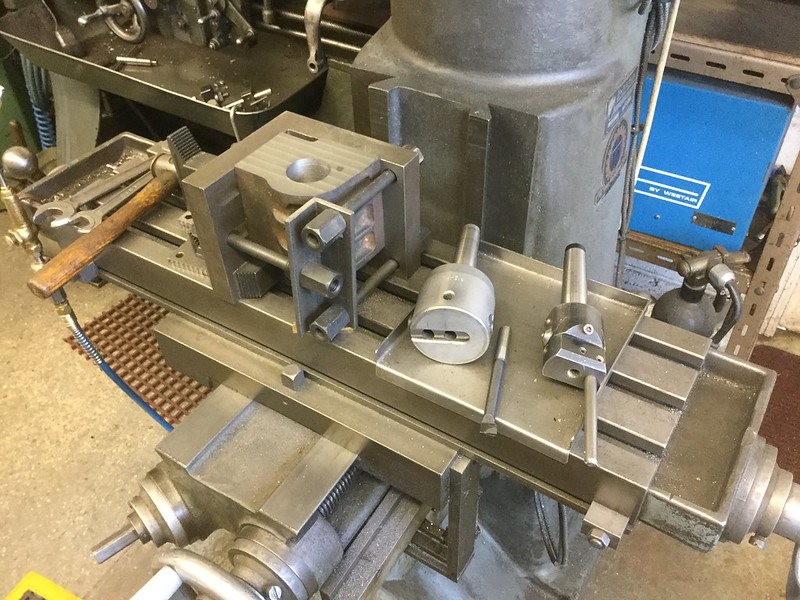 20.10.2016 20.10.2016 by John The Pump, on Flickr My smaller boring had the adjustment but I felt it to to light for the job, neither of the cutters were long enough reach all the way through the bores, but we intended to machine from each end. The solution that I came up with this evening was to grind up an old 2 mm solid carbide end mill that had a shank diameter of 6 mm and fit it in a bar that was long enough to do the whole length of the bore from one side. 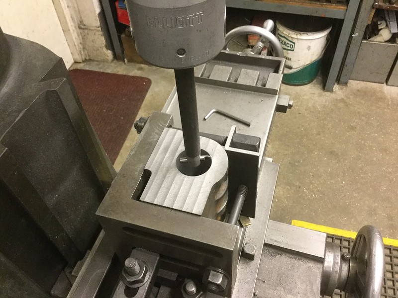 20.10.2016 20.10.2016 by John The Pump, on Flickr |
|
uuu
Elder Statesman
your message here...
Posts: 2,807
|
Post by uuu on Oct 21, 2016 6:53:14 GMT
That looks just the job!
Now you'll have to decide whether to mark out (or even drill and tap) the holes for fixing the covers.
Wilf
|
|
johnthepump
Part of the e-furniture
Building 7 1/4"G Edward Thomas
Posts: 493
|
Post by johnthepump on Oct 21, 2016 10:42:30 GMT
That looks just the job! Now you'll have to decide whether to mark out (or even drill and tap) the holes for fixing the covers. Wilf Hi Wilf, When both cylinders have been rough bored. The next step will be to drill and tap the cylinder mounting holes, then make a plate drilled with the holes to the Reeves drawing and the holes as machined into these cylinders. With this done the frames can be drilled, which was the point of the exercise, so that the horns can be riveted onto the frames as can be the top angle. Then the frames can be bolted back together with all the bits fitted back on. Once that has all been done the axle boxes should be my next priority. John. |
|
johnthepump
Part of the e-furniture
Building 7 1/4"G Edward Thomas
Posts: 493
|
Post by johnthepump on Oct 24, 2016 9:28:26 GMT
I managed to get a little time in the workshop yesterday afternoon, so I got on with rough boring the cylinders and both ended up at 1.6" the finish size is 1.75" but I will do this on the lathe using a between centres boring bar in the same way that I did the B1's cylinders earlier this year. My next task is to machine the little step off of one of the faces of the angle plate that I mounted the cylinders on as it will be in the way when I remount the cylinder to drill and tap the mounting holes. When I returned indoors the wife was watching something on television that I didn't much care fore, so I went and made some sultana scones for tea.  23.10.2016 23.10.2016 by John The Pump, on Flickr |
|
|
|
Post by springcrocus on Oct 24, 2016 15:07:49 GMT
I managed to get a little time in the workshop yesterday afternoon, so I got on with rough boring the cylinders and both ended up at 1.6" the finish size is 1.75" but I will do this on the lathe using a between centres boring bar in the same way that I did the B1's cylinders earlier this year. My next task is to machine the little step off of one of the faces of the angle plate that I mounted the cylinders on as it will be in the way when I remount the cylinder to drill and tap the mounting holes. When I returned indoors the wife was watching something on television that I didn't much care fore, so I went and made some sultana scones for tea.  If you need any help in reducing the size of those, I'm happy to pop round and help! I see another one been nicked from the corner - I'm sure there was eleven when I looked earlier. Steve |
|
|
|
Post by joanlluch on Oct 24, 2016 16:12:19 GMT
Hi Steve, nice photo editing, LOL.
|
|
johnthepump
Part of the e-furniture
Building 7 1/4"G Edward Thomas
Posts: 493
|
Post by johnthepump on Oct 28, 2016 10:10:47 GMT
Tuesday evening in the Pumphouse saw the second replacement axle for one of the clubs passenger trolleys finished, still requires A N other to paint. A piece of 8mm steel plate was brought in by the Clubs Secretary which he had milled to fit his B1 the requirement was, could I put in the bend to match his old grate, with the aid of a large propane torch it was made red hot around the bend area and then swiftly under the fly-press with one of those present saying strike while the irons hot, he had served his time at W Hurst & sons Newport back in the old days when they were full ironmongers complete with a foundry, you can see all sorts of drain covers with their name cast in to this day all over the Island they even cast some of the chimneys for the O2s. The bent plate was allowed to cool and was taken away back to his workshop to be made into a Rosebud grate, this has been up on the 5"G forum on Facebook for those interested in the comments but here is a photo before it is tried out. John. 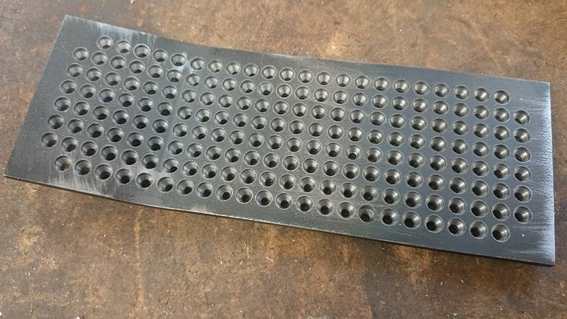 25.10.2016 25.10.2016 by John The Pump, on Flickr |
|
johnthepump
Part of the e-furniture
Building 7 1/4"G Edward Thomas
Posts: 493
|
Post by johnthepump on Oct 28, 2016 10:56:59 GMT
Wednesday evening in the Pumphouse, I had found a little time earlier in the week to make the the drill jig plate to drill the cylinder holes in the frames whilst being bolted into the holes that are already there as the Reeve's drawings. When I place the jig plate onto the frames I was somewhat surprised to find that the top two hole were out by about half a hole. It was back in 2004 when Wilf and I drilled the frames by co-ordinate drilling on the mill with DRO, so how we got this wrong I do not know we had made one spaced at 1.125" and the lower one spaced at 1.25". My jig was drilled to 1.25" spacing and using a CAD drawing to get the cylinder into the correct place, so I thought I better look at my set of Reeve's drawing to check and all I can say is that all those years ago we got it half right, for the hole spacing on the frames drawing calls for 1.125" but on the cylinders drawing the the spacing dimension is 1.25". As the centre and lower holes line up the jig can still be used. 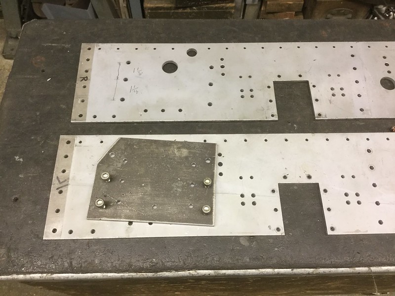 24.10.2016 24.10.2016 by John The Pump, on Flickr The angle plate that we had used to hold the cylinders has a step on one of the inside faces which I wanted to remove so that I could mount them up for drilling and tapping. The problem was how to hold the angle plate on the mill when the whole face needs machining and a fly cutter has to used because of the up stand. There were two 5/8" whitworth threaded holes in the plate and I hit on the idea by making two threaded inserts 3/8" long drilled 6.1mm and slotted for a large screwdriver, when inserted they leave a pocket for a caphead bolt to lie below the surface. As the plate overhung the front of the mill table I drilled and tapped the stops to take 6 mm bolts and with the stop pin removed as was able to continue. John. 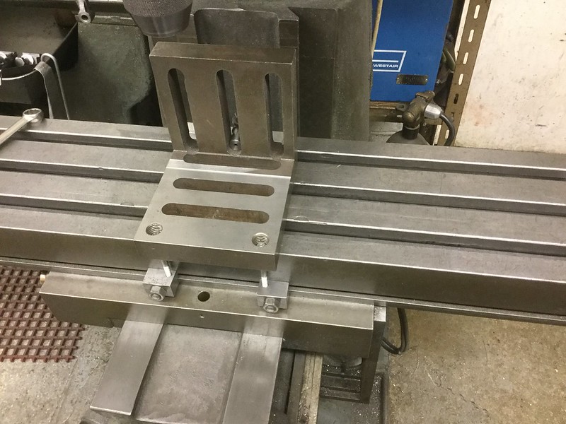 26,10,2016 26,10,2016 by John The Pump, on Flickr |
|
|
|
Post by springcrocus on Oct 28, 2016 13:32:06 GMT
A very clever clamping solution. Top marks, that man.  Steve |
|
johnthepump
Part of the e-furniture
Building 7 1/4"G Edward Thomas
Posts: 493
|
Post by johnthepump on Oct 28, 2016 15:27:47 GMT
If it would only stop the scones from disappearing 😜🍪
|
|
|
|
Post by springcrocus on Oct 28, 2016 18:28:20 GMT
If it would only stop the scones from disappearing 😜🍪 Well blow me down! I see what you mean...  Are you sure that Wilf hasn't been sneaking into the Pumphouse canteen while no one's looking?  Steve |
|
uuu
Elder Statesman
your message here...
Posts: 2,807
|
Post by uuu on Oct 28, 2016 19:35:23 GMT
Not me. I'm in London.
Wilf
|
|
jma1009
Elder Statesman
Posts: 5,900
|
Post by jma1009 on Oct 28, 2016 22:15:31 GMT
Hi John,
Wheeler and Hurst (as WH Hurst became later) never made chimney castings for the ex-LSWR O2s. They made replacement chimneys for the Isle of Wight Central locos in the post WW1 Willmott era including for the IWCR stud of Terriers, and 'pride of the fleet' Black Hawthorn No.6 4-4-0T, one of the few locos the IWCR bought new. John Salter has a lovely original framed print of this loco on his lounge fireplace mantlepiece.
Cheers,
Julian
|
|
jma1009
Elder Statesman
Posts: 5,900
|
Post by jma1009 on Oct 28, 2016 22:43:42 GMT
This is considerably off topic but might stir a few memories for those on the Isle of Wight.
For my first loco I was told W H Hurst and Sons in Holyrood Street in Newport had a steel yard in Sea Street, adjoining the River Medina which once was full of barges and ships. So I popped into the Holyrood Street shop (which was reminiscent of a very old fashioned ironmongers). The date was June 1983. I was directed to the Sea Street steel yard. A short walk. And an even more antiquated world full of line shafting in the building's roof framing, abutting the River Medina and what were once important wharfs. I stated my requirements to the sole employee of the Sea Street premises, who cut up what I wanted and wrote out a chit. Now the important thing about this chit was that you had to return to the Holyrood Street premises and go up stairs to the office. And about this time after I'd walked up the steps was Mr Hurst Senior in herringbone suit and very tall and with moustache (he was a splitting image in attire and appearance of K N Harris of ME fame). My chit was duly calculated and a few pounds paid.
The Sea Street premises once formed part of Wheeler and Hursts' foundry, the remaining line shafting being for the machining of castings.
I spent 4 years working at nearby Quay Street in the offices of Robinson Jarvis and Rolf. In those days you could buy whatever taps and dies and drills you wanted from W H Hurst and Sons, and silver solder and silver steel from Hunter and Coombes nearby.
Cheers,
Julian
|
|


