|
|
Post by noggin on Feb 27, 2017 20:10:32 GMT
Thankyou for that,I will remember that for future use,Keep the build photos coming , Garry
|
|
|
|
Post by Ben on Mar 5, 2017 15:33:54 GMT
This mis a feature of the 9Fs that doesn't appear on the frame drawing, nor is it mentioned by anyone writing about them, yet every photo and 9F that I have seen, has this joggle in the top of the frames. I have never seen it on any model either: 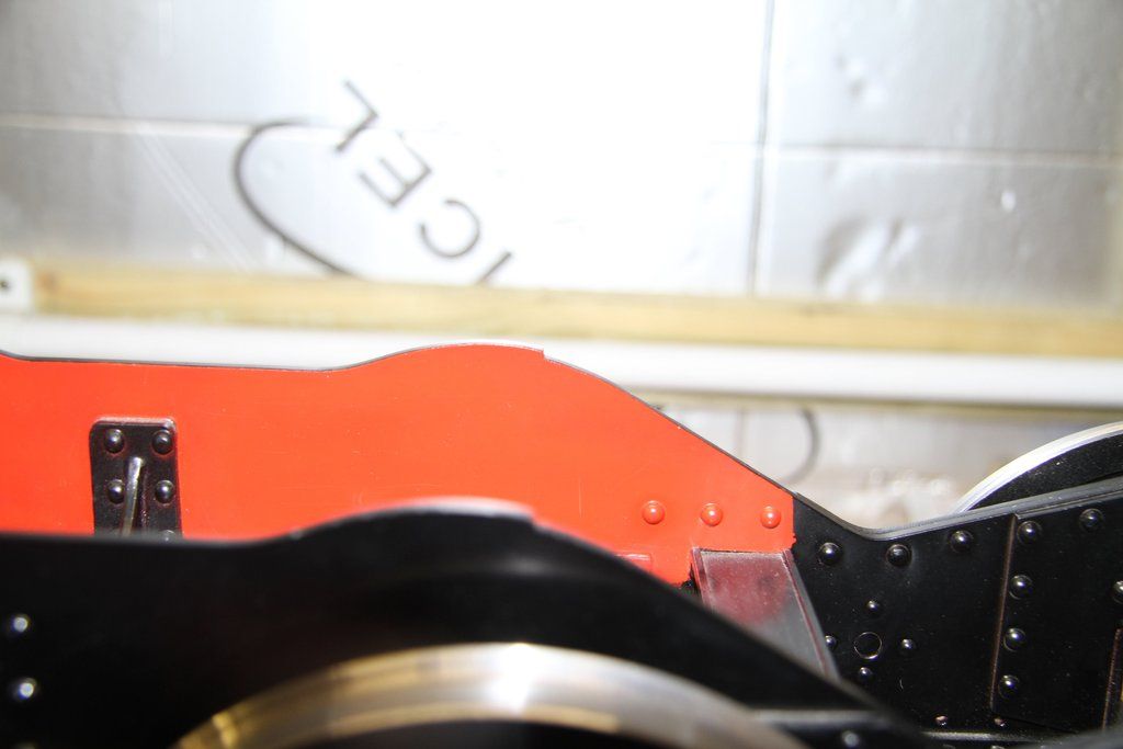 The joggle, on the full-size frames, is 3/4" deep, so 1/16" on a 5"g model. I think this came about possibly because the frame plates were flame cut from both ends because the flame cutting machine was not long enough to do the job in one setting and they had to finish the cut by starting from the other end. Just speculation, but I can see no other reason for this joggle, and as I pointed out, it's on every 9F (unless someone can come up with a photo of a 9F without it. This is 92240, no sign of the joggle however there are these little pads and not just on this part of the frames either, I'd guess that they are datum points 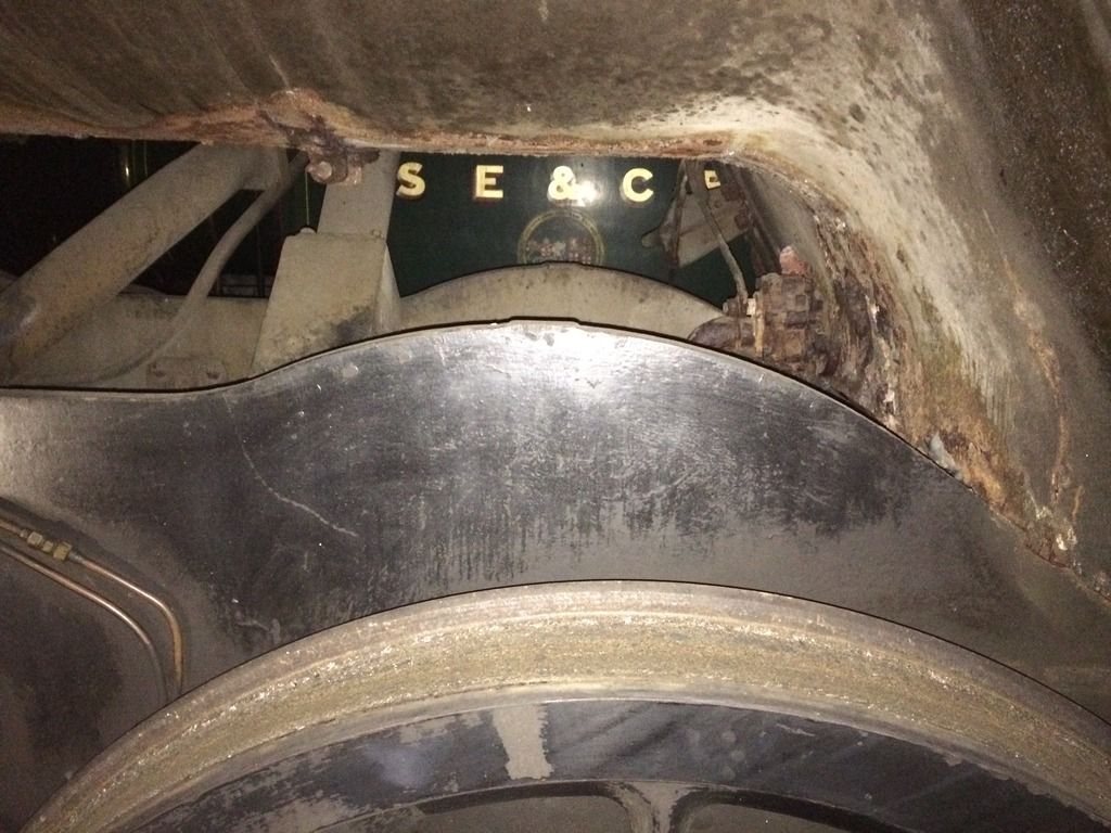 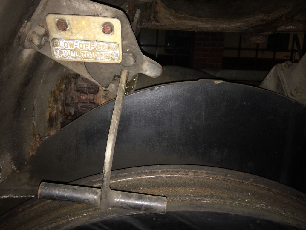  Cheers Ben |
|
|
|
Post by 92220 on Mar 5, 2017 19:34:28 GMT
Hi Ben. That's interesting. The frame shape doesn't look quite right. I wonder if the loco got fitted with new frames, or the frames got modified for some reason. The profile doesn't look quite like the works drawings. I've pulled a section off the frame slotting drawing and also the frames assembly drawing to show what I mean:- Frames Assembly drawing: 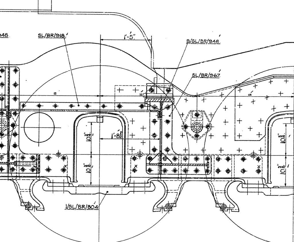 Frame Slotting drawing: 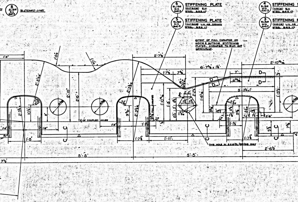 Bob. |
|
|
|
Post by Ben on Mar 6, 2017 2:32:11 GMT
Are there any plans to overhaul '240 ben? They make an superb preserved railway loco, surprisingly economical and easy to work on. Cheers Paul There are plans I believe but no timeline! It's cheaper to do up society owned but Bluebell based engines rather than Bluebell owned ones it would seem. Cheers Ben |
|
|
|
Post by dhamblin on Mar 11, 2017 23:32:30 GMT
Might be a difference between two Works? 92240 was built at Crewe and 92212 at Swindon.
Regards,
Dan
|
|
|
|
Post by 92220 on Mar 12, 2017 10:50:59 GMT
You may be right that this feature is due to different works Dan. 92087 was the first 9F built at Swindon, and that had the joggle in the frames. Maybe I was assuming too much when I said all 9Fs had this joggle. Perhaps it was just all 9Fs built at Swindon. Just goes to show how essential it is to use photographic evidence when building a particular loco to scale, if you want to get it right!
|
|
|
|
Post by 92220 on Mar 16, 2017 19:46:02 GMT
If anyone is contemplating making a 9F boiler to the Les Warnett drawings, or having one made. I've just found another error which he should never have made. He has the blowoff cock tapped boss fitted to the right hand side of the firebox throatplate when looking FROM the front of the loco. It should be on the left hand side when looking from the front. That is to say it is on the right hand side of the loco. The operating handle emerges from above the frames, just in front of the injectors and the blowoff cock is on that side. If you need to get the positioning correct, use Les Warnetts height but the boss should be 0.951" from the boiler centreline, not 1.1/8".
Les also has the boiler barrel too short and the positions of the feedwater clacks, regulator boss, regulator intermediate lever boss, safety valve bosses and manifold boss incorrect. When I have finished drawing up my boiler I will post all the corrections with dimensions.
Bob
|
|
|
|
Post by vulcanbomber on Mar 16, 2017 22:13:45 GMT
If anyone is contemplating making a 9F boiler to the Les Warnett drawings, or having one made. I've just found another error which he should never have made. He has the blowoff cock tapped boss fitted to the right hand side of the firebox throatplate when looking FROM the front of the loco. It should be on the left hand side when looking from the front. That is to say it is on the right hand side of the loco. The operating handle emerges from above the frames, just in front of the injectors and the blowoff cock is on that side. If you need to get the positioning correct, use Les Warnetts height but the boss should be 0.951" from the boiler centreline, not 1.1/8". Les also has the boiler barrel too short and the positions of the feedwater clacks, regulator boss, regulator intermediate lever boss, safety valve bosses and manifold boss incorrect. When I have finished drawing up my boiler I will post all the corrections with dimensions. Bob .... And then you will make 2 boilers to your design so I can have one...? |
|
|
|
Post by 92220 on Mar 17, 2017 11:58:23 GMT
Umm...er..mm...aah don't think I'll be around long enough to do that David!!!
|
|
|
|
Post by 92220 on Apr 23, 2017 17:55:59 GMT
Well it's been a while since I added anything to my thread, but I haven't been slacking......well not much! I've been making the leaf springs for the tender. Unfortunately there is no B.R. drawing available for the springs so I have had to scale off the Tender Arrangement drawing. Luckily B.R. drawings are drawn pretty accurately so it was only a case of import a scan of the area, into Autocad and scale it to fullsize, using a marked dimension as reference. I wasn't sure whether I would need to weaken any of the leafs to obtain the correct deflection, so when I had drawn the spring, I made one up for testing. I also didn't know if heat treatment would alter the deflection either, but I assumed it wouldn't make too much difference. I cut the leafs, over length, on the guillotine, and finished the ends to size on the mill. I then had to make a self centring jig to hold them while drilling the 1/8" dia central rivet hole: 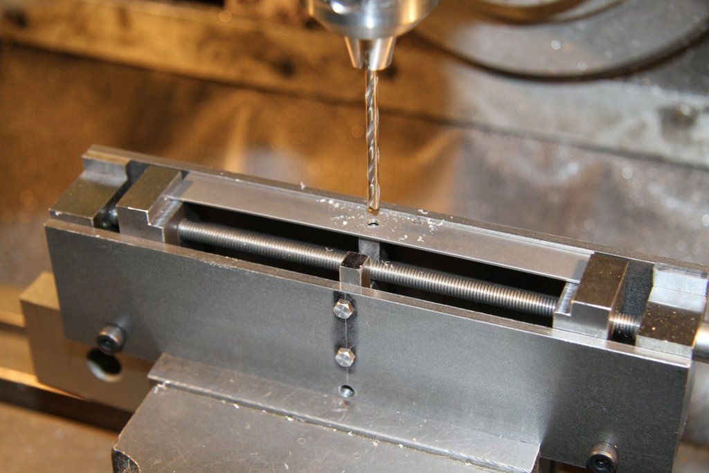 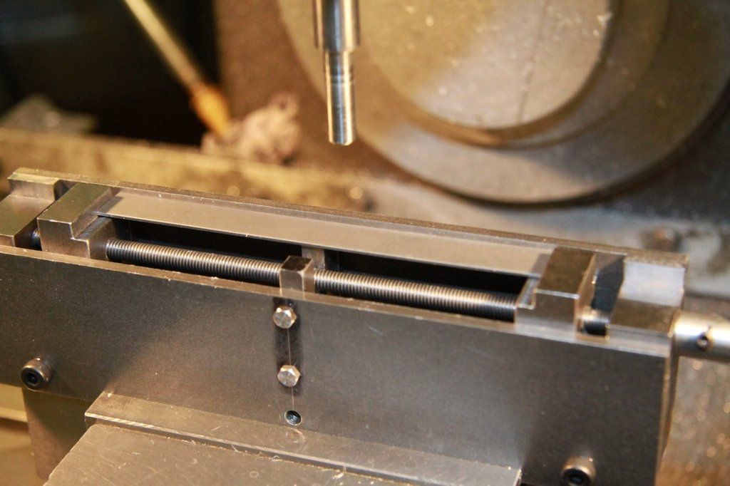 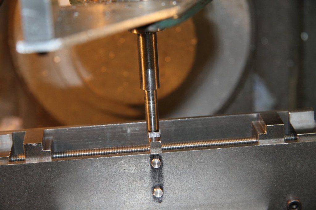 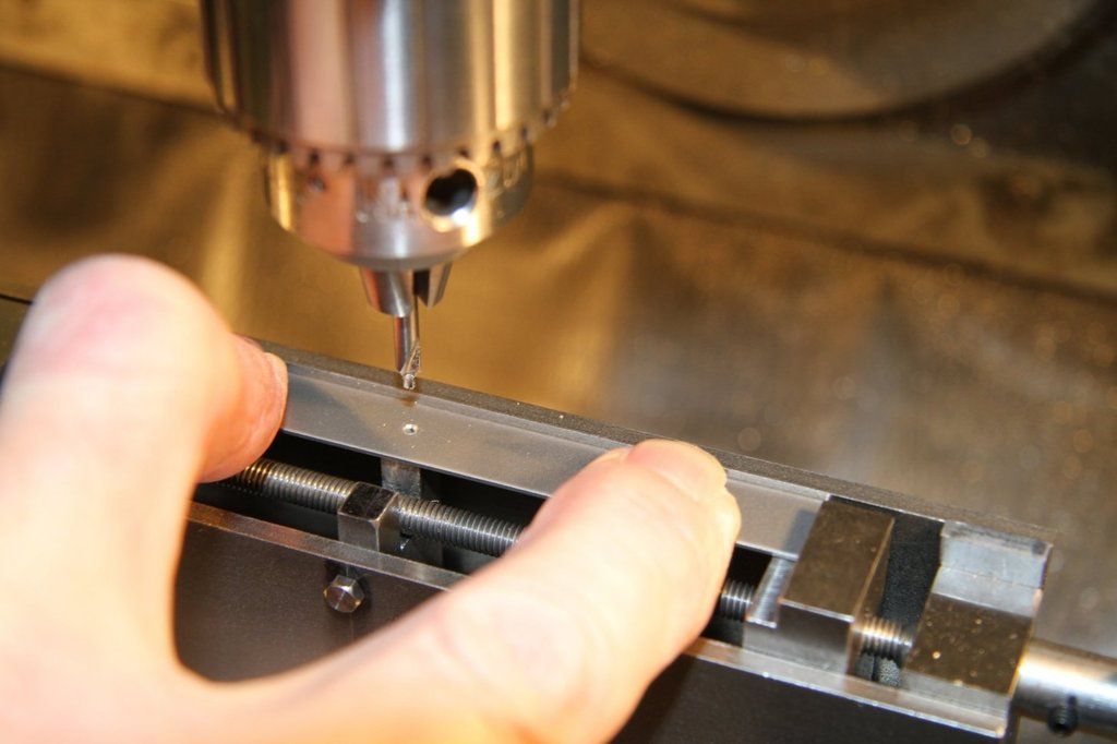 I made up a single leaf spring and calculated that the working weight of the tender would be approx 34.5kgs so I needed a weight of 5.75kgs to load the spring. My 5" lathe chuck plus a bit of steel bar worked out well. I tested the spring and the deflection was only 1/32" and I needed 1/16" movement, no load to full load. I weakened 2 leafs by milling a 1/8" slot each side of the centre hole, and tried it again. Spot on! the deflection was exactly 0.063". My jammy luck!! The next job was to harden and temper the spring to see if that effected the deflection under load. The spring was heated to bright red heat and dropped in a pan of cooking oil. When it was cold it was cleaned, and degreased, with cheap cellulose thinners and the top leaf polished. The spring was then placed on a piece of 10swg steel sheet and heat applied underneath the steel plate. As soon as the polished spring changed to a deep Blue, it was dropped in the oil again, to temper it. Job done! 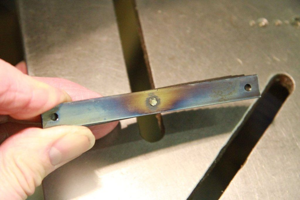 The spring was fitted with a spring strap, and the gap measured between the spring strap and the steel strip the spring was resting on. My chuck, with steel bar, was balanced on the bottom of the spring strap and the gap re-measured. Still 1/16" deflection, and a big sigh of relief!! Machining the concave press tool: 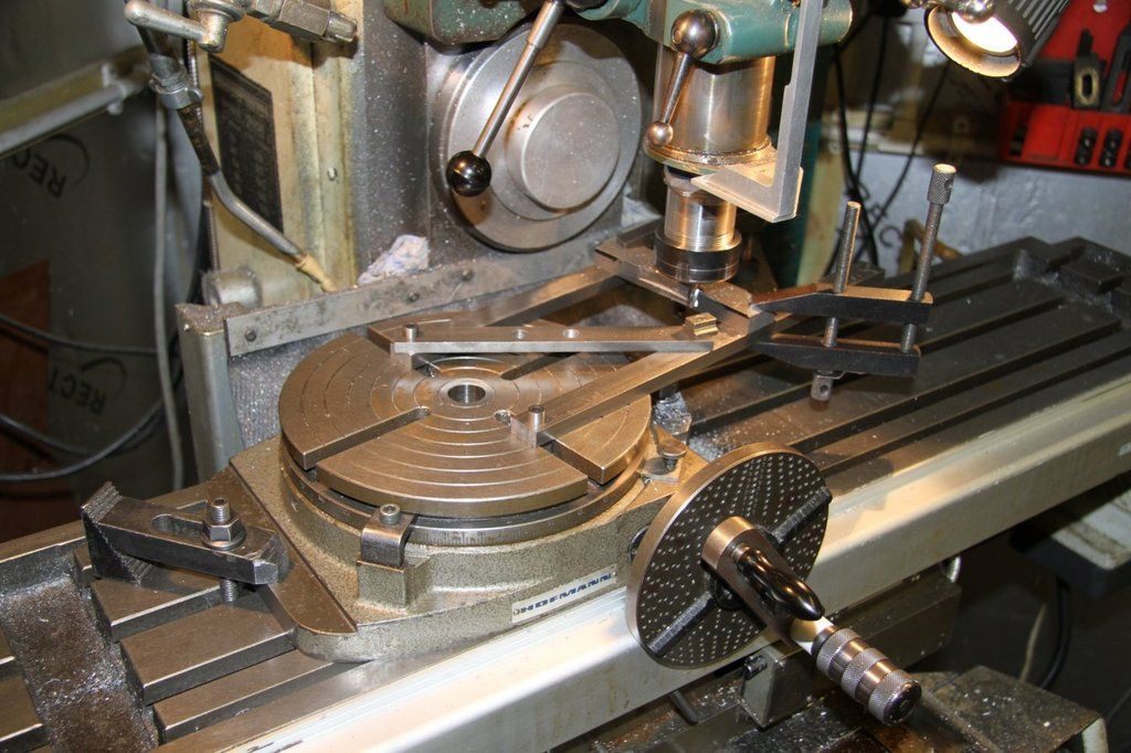 The convex press punch was machined in exactly the same way, but I drew it all up on CAD to find the excat radius required. The DRO was set to 10 thou less than the drawn radius to make sure it all lined up. It was all set up in the toggle press with a couple of bits of spring steel as locations at each end of the curve. 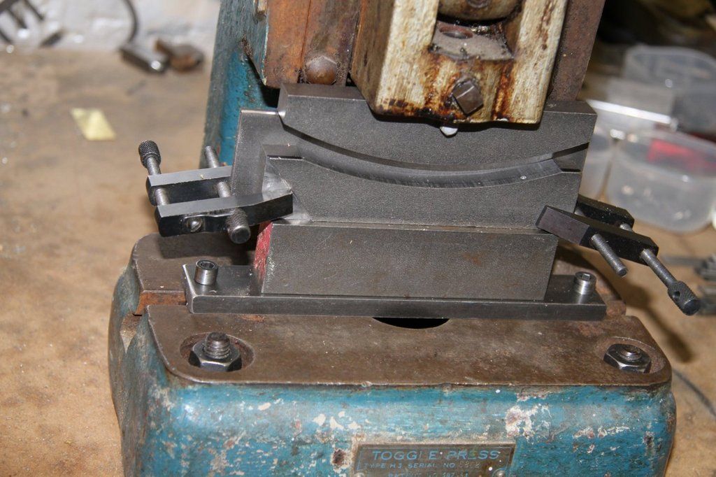 A set of spring leafs: 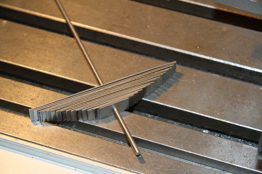 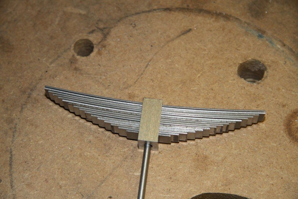 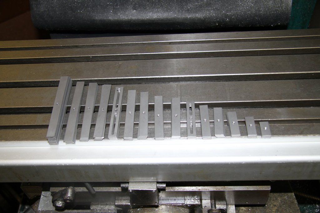 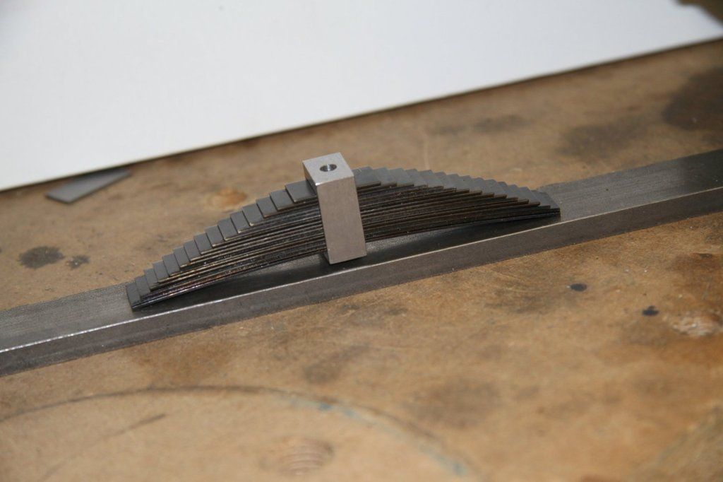 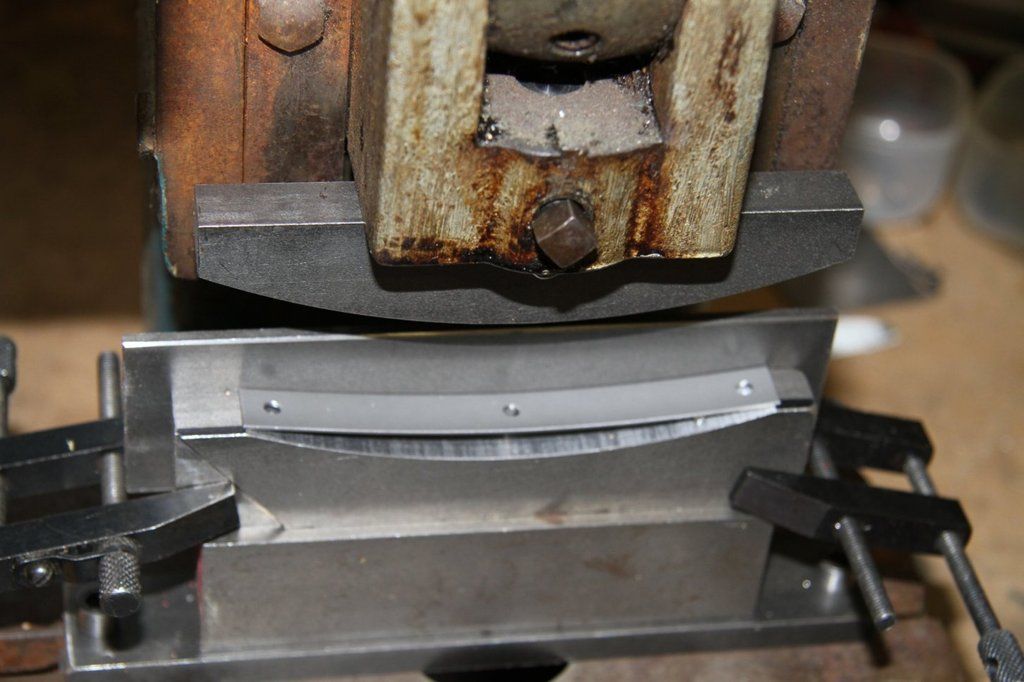 The balancing act: 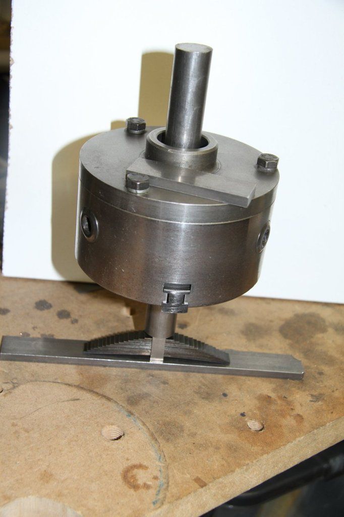 I hope the pics come out in the correct order. |
|
|
|
Post by Roger on Apr 23, 2017 19:18:46 GMT
Superb workmanship as always Bob, very nice indeed. I really like your self centring fixture and press tool.
|
|
|
|
Post by 92220 on May 4, 2017 8:27:34 GMT
The leaf springs are done and now fitted. Next job will be machining the wheels. These are the rubbing inserts in the spring mounting brackets for the springs to bear on: Holding jig for machining the angled edges: 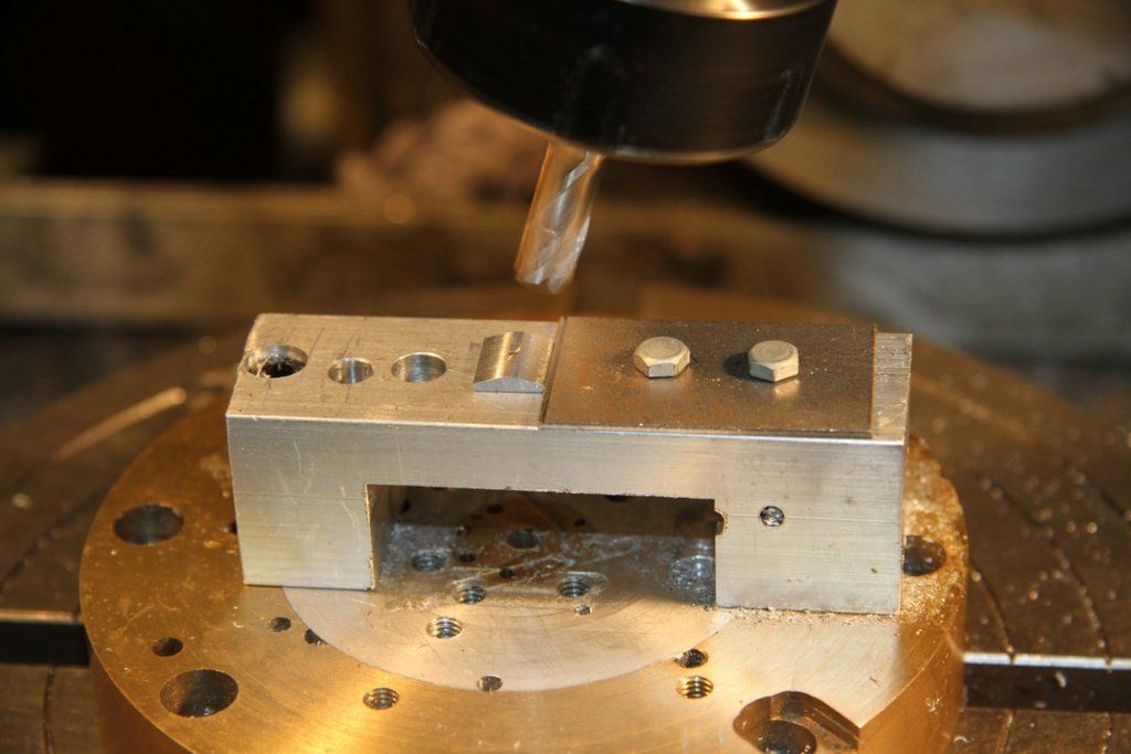 The jig was mounted on the rotary table so that I only had to set the milling head once. 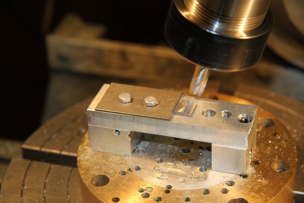  This is one of the spring location hooks, made from 3/32" stainless welding rod. I used this material because it was the easiest to get a very tight bend, with almost no deformation. I used a small oxy/propane torch to get a length of about 1/2" red hot and bent it around the edge of a piece of 20swg steel. The thread is 7BA. 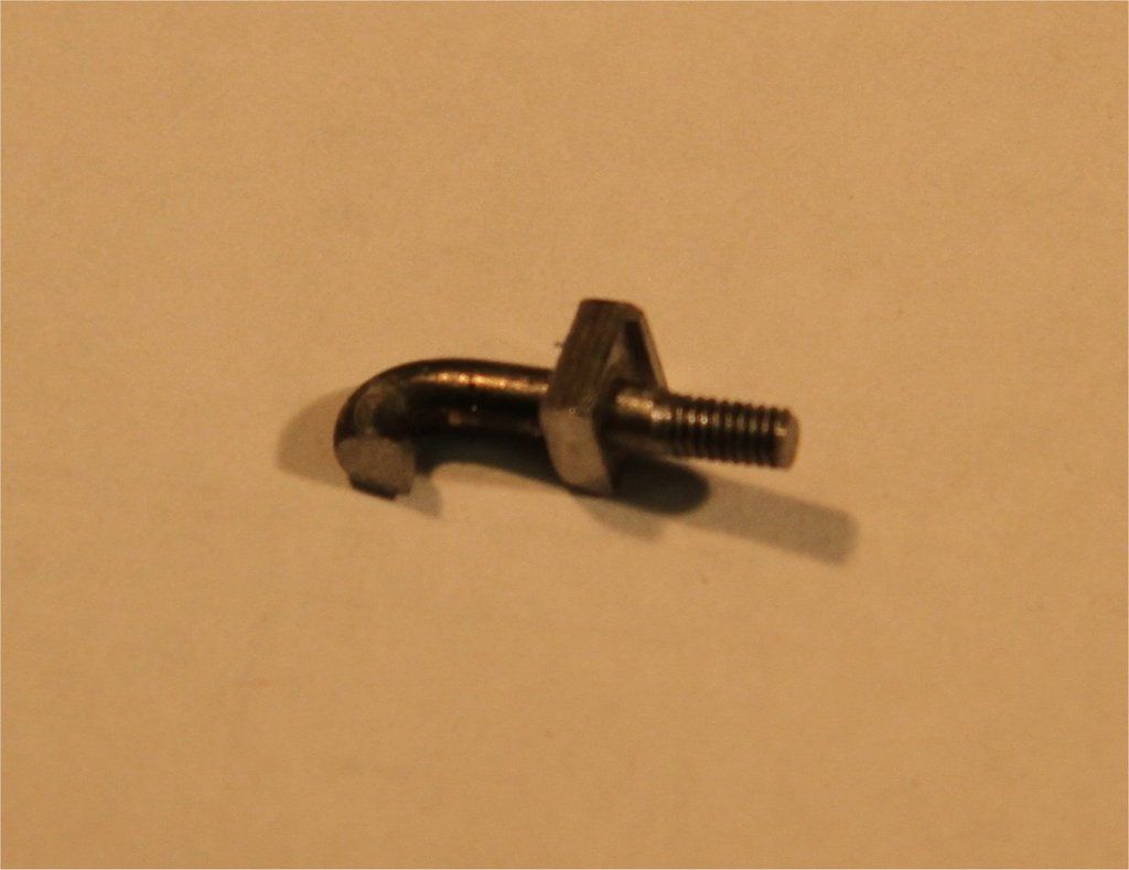 Next, I had to machine the spherical socket in the top of the axlebox pads. This had to line up with the spherical stub on the bottom of the spring collar. I made up a 2-part jig that was clamped in the same position as the leaf springs. The holes were acurately drilled and reamed to ensure the pins could be removed while it was all clamped in the spring hangers. Care was taken, making sure the guide hole for the 6 mm spherical end slot drill, was exactly central. The jig was then clamped in the spring hangers and the small locating piece, between the axlebox guides, removed. The whole frame assembly was clamped to the mill and the spherical socket milled out. With the jig it was all done far quicker than expected. 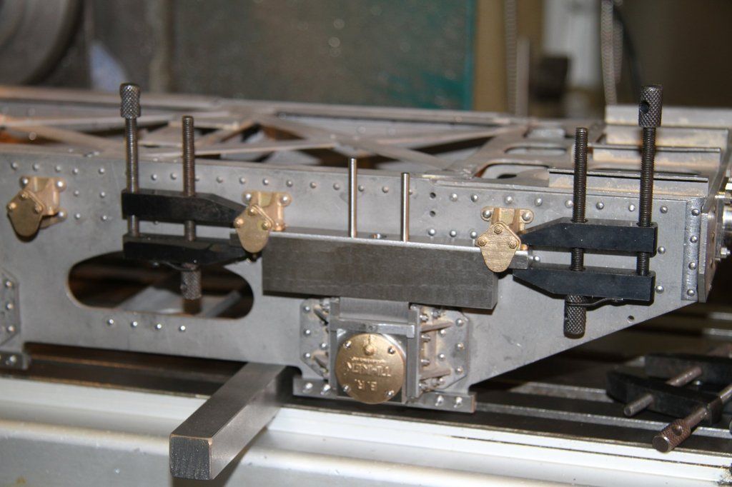 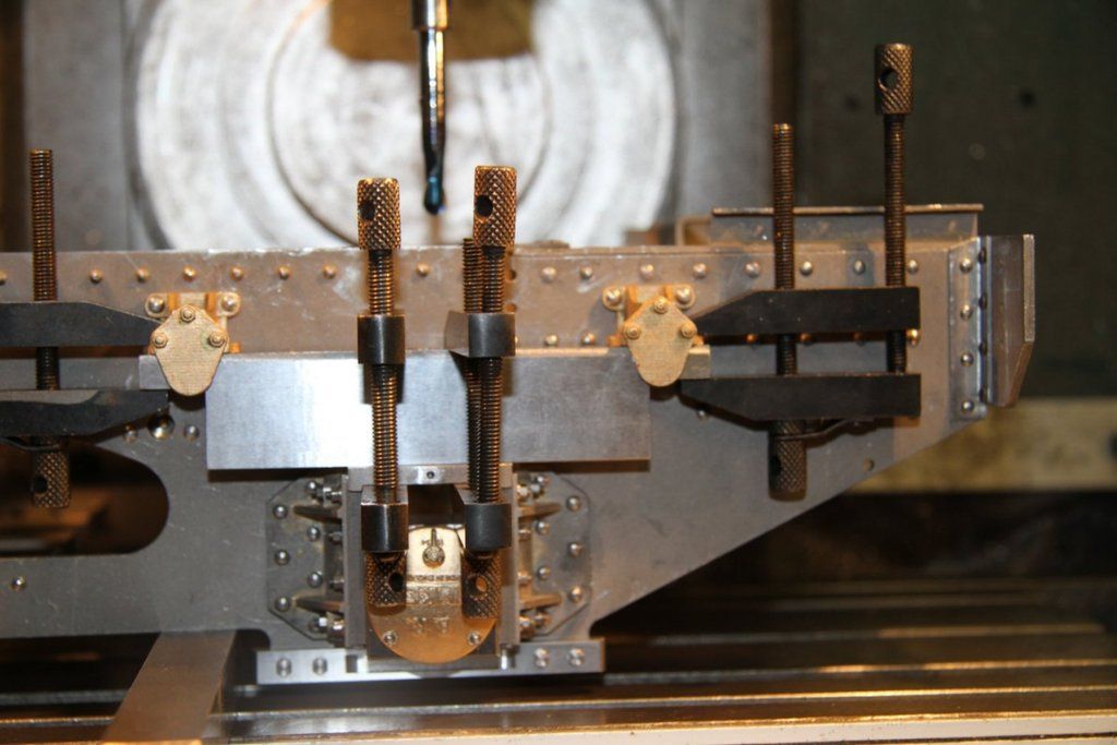 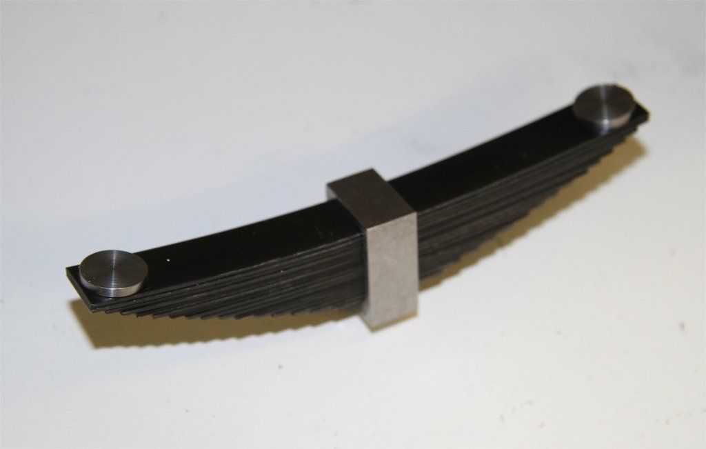 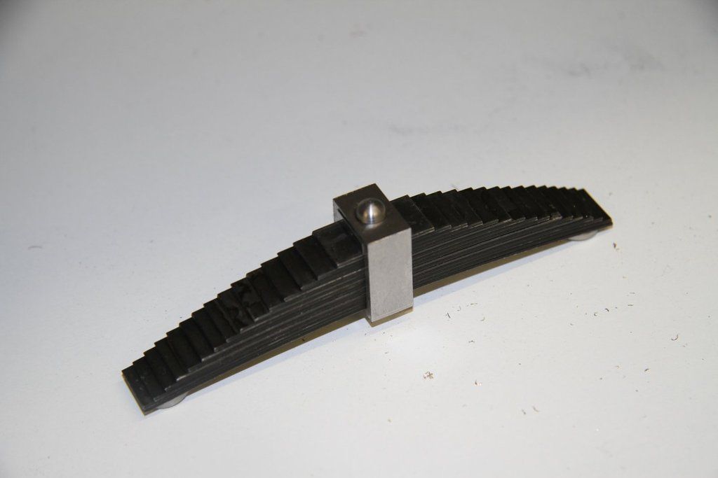 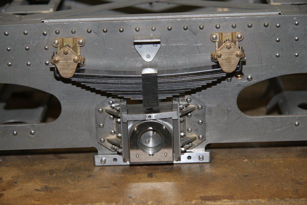 The springs are now fitted: 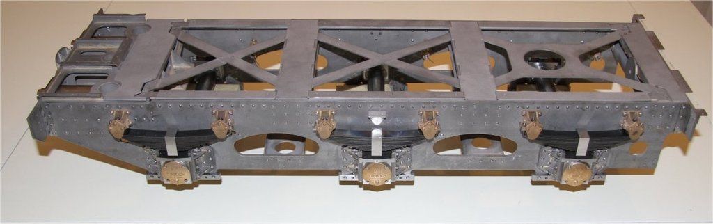 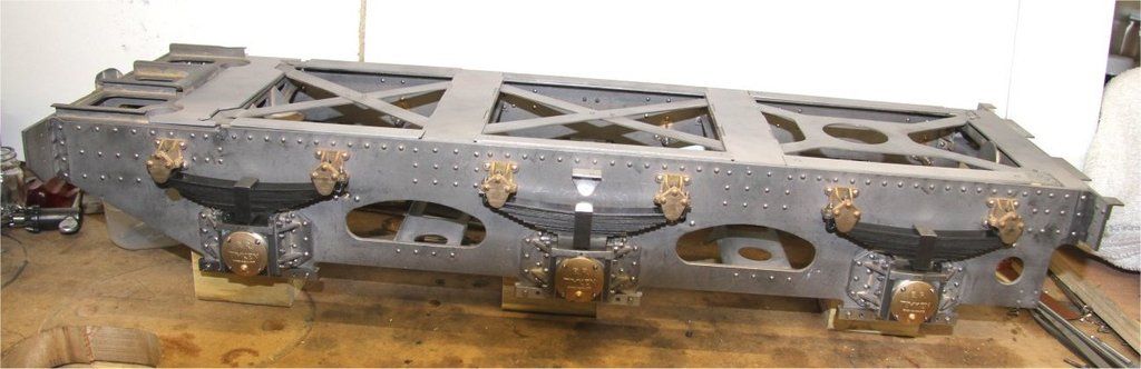 The next job is to finish the wheels. Now don't anybody laugh!! I started to machine the castings and the tool was immediately blunt. I sharpened it and tried again. Same thing! Hmmm. I had totally forgotten that stainless steel, even free cutting stainless, can't be machined at the same speed as EN1a!! Dropped the speed by 75% and all is sorted. Pheww!! |
|
|
|
Post by Jim on May 5, 2017 12:38:35 GMT
I"d agree with Roger, your doing a superb job Bob in recreating 'Evening Star' super detail.
Jim.
|
|
don9f
Statesman
 Les Warnett 9F, Martin Evans “Jinty”, a part built “Austin 7” and now a part built Springbok B1.
Posts: 960 
|
Post by don9f on May 8, 2017 17:09:42 GMT
Hello all, my name is Don and I have only just found this forum and this thread yesterday, so this is post No1 !
I am so impressed with the attention to detail and the desire to build a model so close to the real thing, it's remarkable.
I built a 9F to Les Warnett's drawings and articles in EIM, back in the mid 1980's, however I "overtook" the articles and started gathering all the required info and details from 92220 at York, plus 92214 at Buxton (as it was then) to be able to complete the model with what I thought at the time was a reasonable amount of scale detail.....but nothing to compare with this current build!
I became "involved" with 92214 at Buxton and went on to become the lead engineer of the group, moving everything to the Midland Railway Butterley, where it underwent a further 13 years of restoration, before first runs in July 2003.
It's wonderful to read and see the photos of the progress and how obstacles are overcome.....brings back great memories of my 20 years or so involvement with the real thing. My own model hasn't run now for the same sort of 20 years but it's recently come out of storage to undergo its own restoration to working order. Although I won't be able to do too much about the basic "rolling chassis", I hope to enhance some of the details wherever I can.
I used to be in a society in Grimsby / Cleethorpes and my 9F is portrayed as 92167.....(originally built with mechanical stoker) later allocated to Birkenhead in the mid 1960's, near to where I spent my youth, fitted of course with double chimney, paired towards the end with a BR1C tender and reputed to have been the last 9F in service in 1968.
Many thanks and keep up the good work!
Don
|
|
|
|
Post by simplyloco on May 8, 2017 17:46:43 GMT
Welcome Don. "fitted of course with double chimney," Whatever you do on here, don't mention chimneys...  |
|
|
|
Post by steamer5 on May 9, 2017 7:22:37 GMT
Hi Bob,
I've just finished reading thru this thread, all I can say is inspiring!
You've set the bar very high, will keep following along & learning heaps!
Cheers Kerrin
|
|
|
|
Post by ilvaporista on May 9, 2017 10:21:44 GMT
Hello all, my name is Don and I have only just found this forum and this thread yesterday, so this is post No1 ! I am so impressed with the attention to detail and the desire to build a model so close to the real thing, it's remarkable. I built a 9F to Les Warnett's drawings and articles in EIM, back in the mid 1980's, however I "overtook" the articles and started gathering all the required info and details from 92220 at York, plus 92214 at Buxton (as it was then) to be able to complete the model with what I thought at the time was a reasonable amount of scale detail.....but nothing to compare with this current build! I became "involved" with 92214 at Buxton and went on to become the lead engineer of the group, moving everything to the Midland Railway Butterley, where it underwent a further 13 years of restoration, before first runs in July 2003. It's wonderful to read and see the photos of the progress and how obstacles are overcome.....brings back great memories of my 20 years or so involvement with the real thing. My own model hasn't run now for the same sort of 20 years but it's recently come out of storage to undergo its own restoration to working order. Although I won't be able to do too much about the basic "rolling chassis", I hope to enhance some of the details wherever I can. I used to be in a society in Grimsby / Cleethorpes and my 9F is portrayed as 92167.....(originally built with mechanical stoker) later allocated to Birkenhead in the mid 1960's, near to where I spent my youth, fitted of course with double chimney, paired towards the end with a BR1C tender and reputed to have been the last 9F in service in 1968. Many thanks and keep up the good work! Don Hello Don, Nice to see you on here, I was at Buxton years ago as well and had some good times with Phil B and the lads. My brother, Dave P, who is now Buxton Model Works says Hi. |
|
|
|
Post by 92220 on May 9, 2017 11:56:34 GMT
Hi Don. Welcome to the forum, and thanks Don and Kerrin for those kind comments. I have to admit that the only way to make the model this way, is to work on every individual part as a separate model, otherwise the thought of the time involved would be very 'off-putting'!!
Bob
|
|
don9f
Statesman
Les Warnett 9F, Martin Evans “Jinty”, a part built “Austin 7” and now a part built Springbok B1.
Posts: 960
|
Post by don9f on May 9, 2017 19:13:37 GMT
I kept a diary of hours spent on mine and remember sometimes putting in 16 hour days, it was hard tearing myself away to go to work sometimes! Overall I spent about 3500 hours on mine, for which of course LW had incorporated a lot of "simplification" in its frames construction by using castings etc. But it worked a treat and I had great fun running it at various tracks round the country.....then I started modelling at 12 inches to the foot and that was even more time consuming, so true model engineering had to take a back seat eventually!
Cheers Don
ps Hi Adrian, good to hear from you.
|
|
|
|
Post by 92220 on May 12, 2017 7:37:30 GMT
I don't dare work out how many hours I've put in on mine!!
Bob
|
|


