Post by dhamblin on Sept 30, 2023 14:02:04 GMT
Well Grandad, Dad... done it 
 Safety Valve Setting Tool by Daniel Hamblin, on Flickr
Off the back of the second steam test came the need to adjust the safety valves, so I knocked up a simple tool out of a bit of brass bar with four silver steel prongs to go into the holes on the valve top.
 Regulator Block Caps by Daniel Hamblin, on Flickr
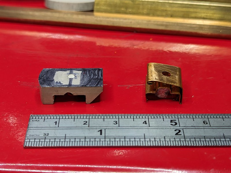
In addition I needed to fix the leaking regulator as per comments in last few posts. Here is the solution - a Fluorosint 500 plastic regulator cap on left and the original bronze sheet test item on the right. The centre section thickness was measured and milled to be an exact fit between the regulator block and underside of the dome cover (allowance for thermal expansion applied as well), with a lubrication hole in the centre again and a slot for the operating mechanism bar to enter. The material at the front (left) is to prevent over travel when opening the regulator, as is the section on the right (rear) when closing it. A chamfer allows clear passage route for steam into the steam pipe.
 Regulator Block Cap by Daniel Hamblin, on Flickr
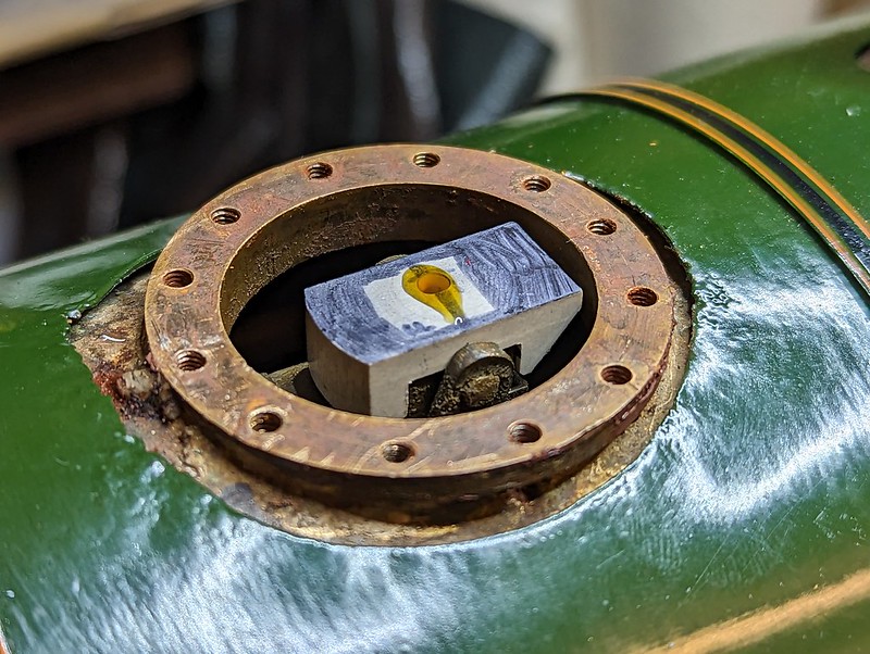
This is what it looks like sitting on the regulator block. After this was taken I refitted the dome cover with a new gasket, put some oil in, screwed in the oil hole screw and did a quick check that the linkages worked - the regulator rod moved through its full arc and I could hear the linkages moving inside the boiler. Or so I thought...
 Leaking Feed Clack by Daniel Hamblin, on Flickr
Steam test 3 didn't go to plan - I had put the dome cover on with the regulator in mid position so I could oil it. I had clearly got the fit wrong and the regulator was now locked half open, which became evident as I tried to get the fire going, with pressure rising to about 40psi before falling back because it was just venting out of the blast pipe. This was validated by removing the oiling screw when it was cold and seeing that the white Fluorosint didn't move when I operated the regulator, but the flex in the linkages still made a noise. Also the injector feed clack started leaking, here you can see steam bubbling between the pipe and fixing plate.
Dome cover off, files out, thin the block until it moved freely with the dome cover on. Had to take a bit off the underside of the front section as with the regulator fully open it wedged on a step on the manifold block (you can just see it in previous photos / videos). The feed clack was also removed and extra silver solder added to the joint and dressed back flat.
Steam test 4 went much better - safety valves set and here you can see the regulator being tested. I can shut it now, possibly with a few goes at higher pressure. The backhead gland also started leaking, which required further attention.
 Steam Test 5 by Daniel Hamblin, on Flickr
Just a record shot of the fire with the blower cracked open. The injector was tested at various pressures, which showed that the steam feed connection was leaking badly at the union. Obviously this meant a lot of the kinetic energy was being lost so the injector wasn't feeding anywhere near the required amount.
 Cab Removed by Daniel Hamblin, on Flickr
LBSC's design has the injector valve on top right of the cab, with a pipe running down and then under the cab to the injector, which sits next to the left hand side of the ashpan. To release the pipe in order to solder a new nipple on the cab had to be completely removed. I took the opportunity to nip up a few unions that were inaccessible when the cab is fitted and during reassembly reattached the brake control valve pedestal and pipes.
 Pipework Repair by Daniel Hamblin, on Flickr
New nipple soldered on the injector steam feed pipe and a new union nut added to match, both from Polly Model Engineering.
 Coupling Pin Modifications by Daniel Hamblin, on Flickr
Ticking off the last few jobs - R clip holes added in loco to tender coupling pins. These will prevent the pins working loose during running. These are actually bodyshell clips for my remote control racing car, which turn out are the perfect size.
Steam test 5 was the longest yet, with the fire kept alight for about 90 minutes while I tested various things out. The axle pump got a bit splashy, so tightening the gland nut was added to the list. The injector worked to a fashion, although wasted a fair bit of water out the overflow, as seen here. It did though raise the water level in the boiler so was ticked off as 'works but needs improving'. Also did an accumulation test and made sure the safety valve settings were right for that.
A video of the loco ticking over on the rollers, safety valves feathered and just over 60psi on the gauge.
 Tender Coupling Modifications by Daniel Hamblin, on Flickr
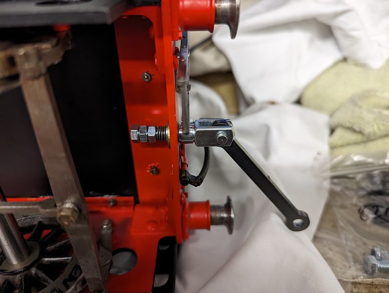
Getting ready for the formal steam test and some track running. The coupling hook removed and an M5 thread adapter made to take the clevis fitting sourced from Maxitrak. Fortunately the M5 screw fitted through the bufferbeam slot so I could re-use the spring and washer off the coupling hook assembly. The latter will be refitted for exhibitions.
 Axle Pump Gland by Daniel Hamblin, on Flickr
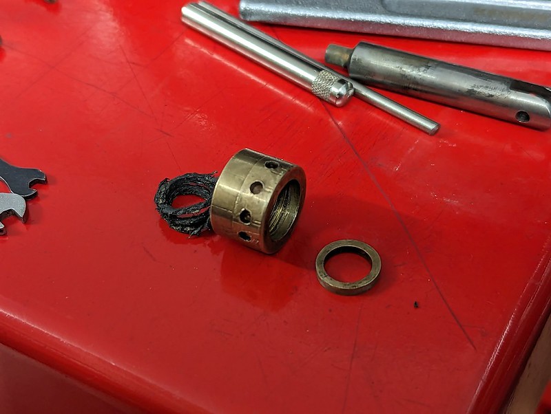
Last minute panic after finding the axle pump gland had come apart the evening before the steam test. LBSC's notes state to make this out of a hard wearing material due to the pump ram (see top right) passing through it. The nut itself appears to be brass, but this ring, through which the ram passes, is made of bronze and must be an interference fit in the nut bore. Managed to press the ring back home and reassemble everything in time.
 Steam Test 1 by Daniel Hamblin, on Flickr
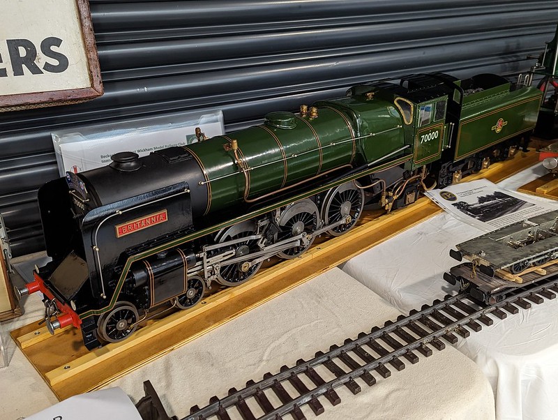
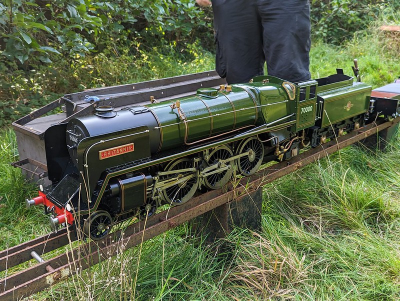
Tuesday 26th September - formal steam test day. Our Chairman has a 100ft section of the societies' portable track in his back garden and offered it as the venue to do the test. Britannia is seen here after being unloaded and coupled up to the driving truck. The truck came in handy to transport the blower, battery, tools, oil can etc. up to the far end where the fire would be lit.
 Steam Test 2 by Daniel Hamblin, on Flickr
Hand pump proven and about to fill the box with charcoal for the warming fire. Blower fitted and various tools in the tender bunker ready for any adjustments.
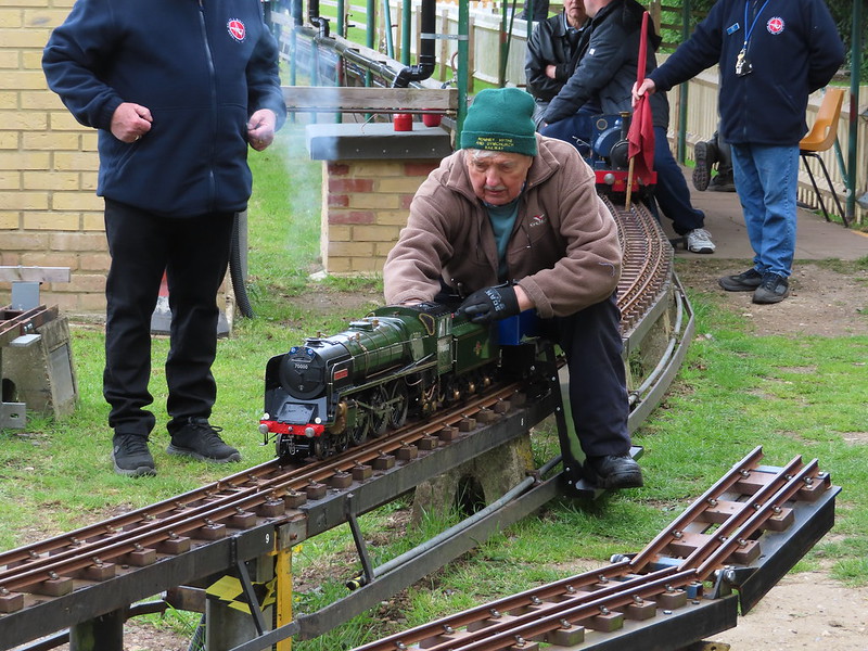
Unfortunately we didn't get many photos or videos of the actual test running up and down the track. Steam test passed on the hand pump and injector, which actually improved to almost run dry after the steam delivery end adaptor union I had made was tightened up further, presumably pushing the cone very slightly deeper into the injector and closing the annular gap. The axle pump started splashing quite quickly after running started and a check showed the ring had popped out again. Interestingly had a few problems with getting the loco started, as though the driving wheels had managed to stop in the 'dead spot', although that might have been the result of that gland ring prevent free movement of the eccentric on the centre axle. Pressure also tended to drop quite quickly after the regulator was opened, which makes me think there is a leak somewhere on the steam circuit, possibly between the cylinder block and frames judging by the amount of oil there. Further running was curtailed by the fire dying at the back of the bed nearest the firehole door, which had also happened on test 5 at home.
Got the pass though, so restoration complete
Had hoped to be at the Leatherhead visitor day tomorrow to get some track running in but until I can reliably keep the fire going that will have to wait for now. Material and tooling on order to make a new axle pump gland nut plus I need to get the loco smartened up ready for our display at the BWWMRC's Model Rail Show on 21st October. The driving truck from Ride on Railways will need the footboards adjusting and the coupling adaptor for the 3 1/2" gauge height couplings completing before a longer track running day to get used to firing a wide firebox loco.
Thank you to everyone on here who has offered advice and encouragement to supplement that from the members of Croydon SME. This thread now switches to maintenance, modification and running reports. Hopefully I'll be able to get out and about with it next year and add a little bit more to the locomotives history.
Regards,
Dan
 Safety Valve Setting Tool by Daniel Hamblin, on Flickr
Off the back of the second steam test came the need to adjust the safety valves, so I knocked up a simple tool out of a bit of brass bar with four silver steel prongs to go into the holes on the valve top.
Regulator Block Caps by Daniel Hamblin, on FlickrIn addition I needed to fix the leaking regulator as per comments in last few posts. Here is the solution - a Fluorosint 500 plastic regulator cap on left and the original bronze sheet test item on the right. The centre section thickness was measured and milled to be an exact fit between the regulator block and underside of the dome cover (allowance for thermal expansion applied as well), with a lubrication hole in the centre again and a slot for the operating mechanism bar to enter. The material at the front (left) is to prevent over travel when opening the regulator, as is the section on the right (rear) when closing it. A chamfer allows clear passage route for steam into the steam pipe.
Regulator Block Cap by Daniel Hamblin, on FlickrThis is what it looks like sitting on the regulator block. After this was taken I refitted the dome cover with a new gasket, put some oil in, screwed in the oil hole screw and did a quick check that the linkages worked - the regulator rod moved through its full arc and I could hear the linkages moving inside the boiler. Or so I thought...
Leaking Feed Clack by Daniel Hamblin, on FlickrSteam test 3 didn't go to plan - I had put the dome cover on with the regulator in mid position so I could oil it. I had clearly got the fit wrong and the regulator was now locked half open, which became evident as I tried to get the fire going, with pressure rising to about 40psi before falling back because it was just venting out of the blast pipe. This was validated by removing the oiling screw when it was cold and seeing that the white Fluorosint didn't move when I operated the regulator, but the flex in the linkages still made a noise. Also the injector feed clack started leaking, here you can see steam bubbling between the pipe and fixing plate.
Dome cover off, files out, thin the block until it moved freely with the dome cover on. Had to take a bit off the underside of the front section as with the regulator fully open it wedged on a step on the manifold block (you can just see it in previous photos / videos). The feed clack was also removed and extra silver solder added to the joint and dressed back flat.
Steam test 4 went much better - safety valves set and here you can see the regulator being tested. I can shut it now, possibly with a few goes at higher pressure. The backhead gland also started leaking, which required further attention.
Steam Test 5 by Daniel Hamblin, on FlickrJust a record shot of the fire with the blower cracked open. The injector was tested at various pressures, which showed that the steam feed connection was leaking badly at the union. Obviously this meant a lot of the kinetic energy was being lost so the injector wasn't feeding anywhere near the required amount.
Cab Removed by Daniel Hamblin, on FlickrLBSC's design has the injector valve on top right of the cab, with a pipe running down and then under the cab to the injector, which sits next to the left hand side of the ashpan. To release the pipe in order to solder a new nipple on the cab had to be completely removed. I took the opportunity to nip up a few unions that were inaccessible when the cab is fitted and during reassembly reattached the brake control valve pedestal and pipes.
Pipework Repair by Daniel Hamblin, on FlickrNew nipple soldered on the injector steam feed pipe and a new union nut added to match, both from Polly Model Engineering.
Coupling Pin Modifications by Daniel Hamblin, on FlickrTicking off the last few jobs - R clip holes added in loco to tender coupling pins. These will prevent the pins working loose during running. These are actually bodyshell clips for my remote control racing car, which turn out are the perfect size.
Steam test 5 was the longest yet, with the fire kept alight for about 90 minutes while I tested various things out. The axle pump got a bit splashy, so tightening the gland nut was added to the list. The injector worked to a fashion, although wasted a fair bit of water out the overflow, as seen here. It did though raise the water level in the boiler so was ticked off as 'works but needs improving'. Also did an accumulation test and made sure the safety valve settings were right for that.
A video of the loco ticking over on the rollers, safety valves feathered and just over 60psi on the gauge.
Tender Coupling Modifications by Daniel Hamblin, on FlickrGetting ready for the formal steam test and some track running. The coupling hook removed and an M5 thread adapter made to take the clevis fitting sourced from Maxitrak. Fortunately the M5 screw fitted through the bufferbeam slot so I could re-use the spring and washer off the coupling hook assembly. The latter will be refitted for exhibitions.
Axle Pump Gland by Daniel Hamblin, on FlickrLast minute panic after finding the axle pump gland had come apart the evening before the steam test. LBSC's notes state to make this out of a hard wearing material due to the pump ram (see top right) passing through it. The nut itself appears to be brass, but this ring, through which the ram passes, is made of bronze and must be an interference fit in the nut bore. Managed to press the ring back home and reassemble everything in time.
Steam Test 1 by Daniel Hamblin, on FlickrTuesday 26th September - formal steam test day. Our Chairman has a 100ft section of the societies' portable track in his back garden and offered it as the venue to do the test. Britannia is seen here after being unloaded and coupled up to the driving truck. The truck came in handy to transport the blower, battery, tools, oil can etc. up to the far end where the fire would be lit.
Steam Test 2 by Daniel Hamblin, on FlickrHand pump proven and about to fill the box with charcoal for the warming fire. Blower fitted and various tools in the tender bunker ready for any adjustments.
Unfortunately we didn't get many photos or videos of the actual test running up and down the track. Steam test passed on the hand pump and injector, which actually improved to almost run dry after the steam delivery end adaptor union I had made was tightened up further, presumably pushing the cone very slightly deeper into the injector and closing the annular gap. The axle pump started splashing quite quickly after running started and a check showed the ring had popped out again. Interestingly had a few problems with getting the loco started, as though the driving wheels had managed to stop in the 'dead spot', although that might have been the result of that gland ring prevent free movement of the eccentric on the centre axle. Pressure also tended to drop quite quickly after the regulator was opened, which makes me think there is a leak somewhere on the steam circuit, possibly between the cylinder block and frames judging by the amount of oil there. Further running was curtailed by the fire dying at the back of the bed nearest the firehole door, which had also happened on test 5 at home.
Got the pass though, so restoration complete
Had hoped to be at the Leatherhead visitor day tomorrow to get some track running in but until I can reliably keep the fire going that will have to wait for now. Material and tooling on order to make a new axle pump gland nut plus I need to get the loco smartened up ready for our display at the BWWMRC's Model Rail Show on 21st October. The driving truck from Ride on Railways will need the footboards adjusting and the coupling adaptor for the 3 1/2" gauge height couplings completing before a longer track running day to get used to firing a wide firebox loco.
Thank you to everyone on here who has offered advice and encouragement to supplement that from the members of Croydon SME. This thread now switches to maintenance, modification and running reports. Hopefully I'll be able to get out and about with it next year and add a little bit more to the locomotives history.
Regards,
Dan