|
|
Post by terrier060 on Jan 11, 2019 15:47:23 GMT
I am still thick with virus which will not go away so have spent my time at the PC thinking about the cab. As well as all the other help I have had with the cab, Jim has been very helpful with details and we have corresponded privately. But some of this correspondence is interesting enough, I thought, to be posted here. Jim, you are so right about the cab needing a great deal of thought. Your pics are really helpful and I too am worried about the top of the cab sides, which until they are fixed to the floor are only supported at the top by the stainless beading around the cab doors. I am going to make the front and sides first, which from my thread you see are made in seven pieces which fit nicely on the Tormach. There is the front spectacle plate, the lower front pieces, which have a hole for the crosshead pump bypasses, and the front and rear side sections. I am making them identical for the A1 and A!X as from visiting the loco after gaps of many years, a lot of the cab has been replaced as has the roof, as it rusts away - probably more than once in its lifetime. Fenchurch is still largely flush-riveted so I will not have the hard job you have had, which is beautifully done by-the-way. When these are made, I will have a look and see whether I can drive with the roof on, or with half a roof. Hopefully the latter, as locos without any roof above the header look a bit odd. Whether correct or not for the A1 version, the A1X has a convenient stiffening piece on the front of the bunker (see photo), and as there are no early pictures to my knowledge of the inside of Fenchurch's bunker as an A1, I shall incorporate it on both versions. It makes a very satisfactory place to split the rear spectacle plate and tuck it into the rear cab. It can be held in place by the pin on the bunker coal door which is used to keep the door in the open position. You mention the reversing quadrant. I intend to stiffen mine by having a steel plate inside the box, or maybe I will just use a thicker material in steel for that part of the box. It looks like it should be a rigid setup once all the pieces are in place. I am also going to be controversial in the way I construct the cab. I have been in touch with the technical guys at Permabond and Ion has taken an interest in what we are doing and is having a look at suitable adhesives. I know there has been a lot of tutt-tutts on the Forum, but if one never tries something different it makes life very boring. In any case if they can stick the Second Severn Crossing together with glue as well as aircraft wings it must be OK!! As far as the roof goes I am in two minds. I can either make a die on the Tormach and make them in brass as I did with the water tank lids, or do as Julian has done and beat them in copper, or as you have done Jim and fabricate them. Watch this space! 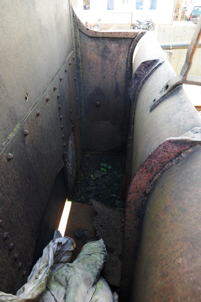 Bunker Bunker by ed cloutman, on Flickr |
|
|
|
Post by terrier060 on Jan 11, 2019 18:51:18 GMT
For some reason Flikr would not allow me to load these last night but it's OK now. They show the cab details and the roof. 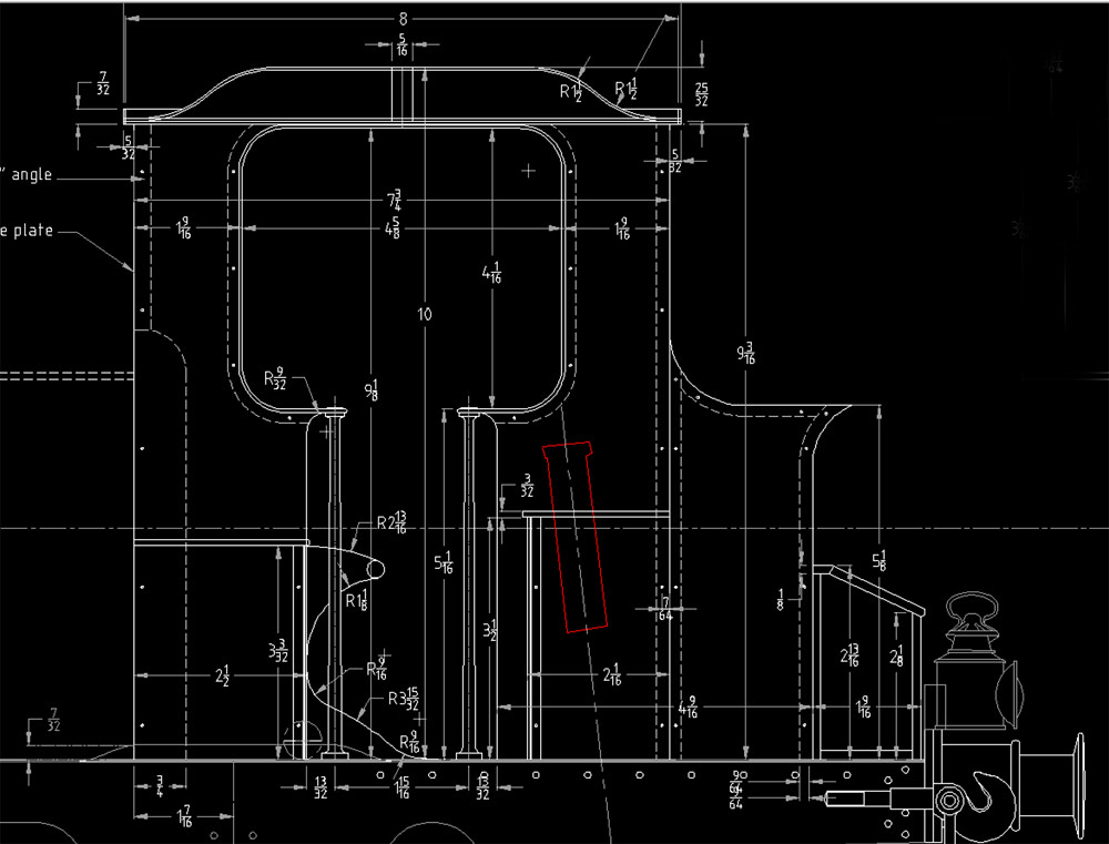 Cab side elevavtion Cab side elevavtion by ed cloutman, on Flickr 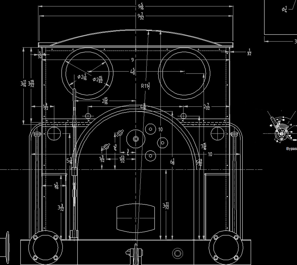 Cab rear elevation Cab rear elevation by ed cloutman, on Flickr This is the state of Fenchurch's roof at present and it was renovated not so long ago by the Villa Team. There are some great pictures of volunteers working on Fenchurch on the Bluebell website. One of the roof is shown below. 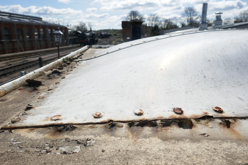 Fenchurch Roof Fenchurch Roof by ed cloutman, on Flickr 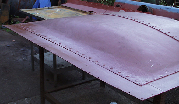 Fenchurch roof renovation Fenchurch roof renovation Photo by the Villa Group, Bluebell Railway |
|
|
|
Post by Roger on Jan 11, 2019 19:07:49 GMT
Hi Ed,
That's a challenging shape to make the roof. Are you going to CNC a former to beat that over?
|
|
|
|
Post by terrier060 on Jan 11, 2019 19:47:50 GMT
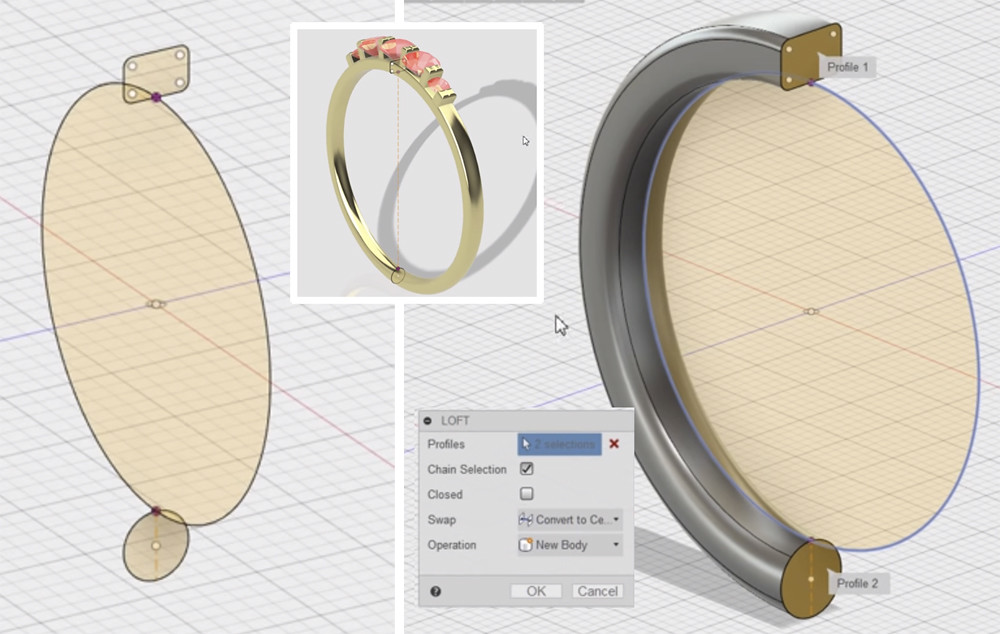
Yes Roger I will try to use the Tormach if I can work out how to draw it in 3D. I have had a couple of goes using Loft as you suggested, but have not got is right at the moment. I will post what I have done for you to take a look at.
|
|
|
|
Post by Cro on Jan 11, 2019 20:53:53 GMT
If you get stuck with the 3D shape Ed I could take a look.
Adam
|
|
|
|
Post by Jim Scott on Jan 11, 2019 21:19:43 GMT
Ed
Does that bunker belong to Fenchurch? It looks pretty wrecked, I note the floor rusted through and the extra reinforcement on the rear of the cab, also the additional stiffening angles on the bunker end plate. A photo of Boxhill's bunker here for comparison.
With regard to your cab roof and the use of adhesives for construction, there are many ways of skinning a cat, as the saying goes...
Jim
 |
|
|
|
Post by terrier060 on Jan 11, 2019 23:20:05 GMT
Yes Jim it is Fenchurch - I am afraid the poor old engine is in a pretty poor shape, but I read somewhere it is going for overhaul in 2022. I have the Boxhill bunker image as well, but yours is better. I intend to follow that as it is simpler with those strengthening straps and I suspect that is more how it was originally. I am not sure whether they all had vertically split backs to the cab. Cetainly not like that on the drawings or on the present Fenchurch. Again variation is dependent on condition and replacing rusting parts in the 150 years of service. Adam that is very kind. I have my effort here if that makes any sense. The roof shape fore aft is correct and the large circle represents the curve of the roof left to right. I have not worked out how to marriage the two shapes. 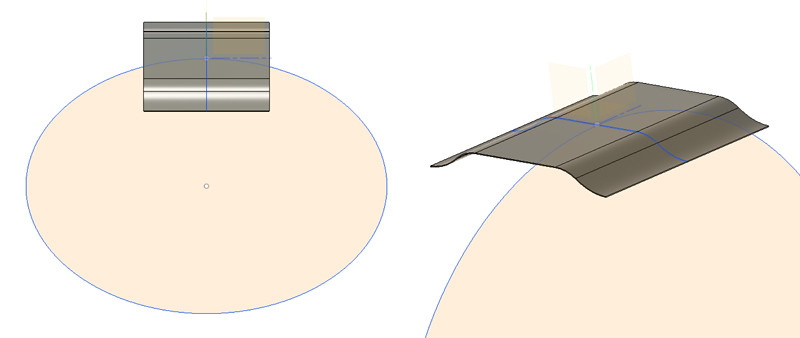 Roof Roof by ed cloutman, on Flickr |
|
|
|
Post by Roger on Jan 12, 2019 8:56:25 GMT
Hi Ed, I'd treat it as a solid instead of sheet until you have the shape, and then create the sheet from the surface of that. If you try to merge those two shapes, I think you'll just get sharp lines where they intersect. This is how I'd try to model it using Loft curves, but that might be a struggle too it's complained about 'Cusps' being created when I've tried to get this to the edge so I've left that off for the moment. All I've done in the picture is to create a series of planes and draw some cross sections on each one. Then I've used a Loft to join them smoothly together. You would need to draw them on both sides of the centre line else it wouldn't blend nicely across the top of the roof. You would have to play with the cross sections to get it to look right. It's not a quick job, and you might have to add extra intermediate cross sections where the curve changes more so that you can bully it into taking the shape you want. The shape below is created from three sketches, the ones at the ends and one you can just see as a dotted blue line near the LH edge 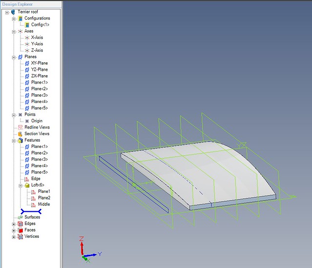 Roof using loft Roof using loft by Anne Froud, on Flickr These shapes are fraught with problems because the maths pack can complain and then it can be really hard to find out how to resolve the problem. I think the tricky bit here is that the edge is flat and the section immediately inboard of that might want to dip down. One possible solution is to add a couple of extra planes outside of the section which repeat the flat edge. Including those would try to keep that edge flat. |
|
|
|
Post by terrier060 on Jan 12, 2019 10:14:21 GMT
|
|
|
|
Post by Roger on Jan 12, 2019 10:23:33 GMT
He's using a 'Guide rail', but I've had so much trouble with those that I avoid them completely now. The problem is that the 'Guide rail' has to intersect the different sections absolutely precisely, and if it's not geometrically perfect, it just throws an error that gives no clue as to where that error is. I've wasted days trying to get things to work with those and I'm not ever going there again.
Lofts are a lot less troublesome, even though they take a bit more effort to define. The good thing about chopping something into sections is that you can more easily change the way the curve progresses. This is how I've done the chimney and also the coupling hook.
|
|
uuu
Elder Statesman
 your message here...
Posts: 2,807
|
Post by uuu on Jan 12, 2019 13:11:40 GMT
If this was a car, you'd use a wheeling machine to produce the compound curve. I used to work at a petrol station next to a panel beaters, and it was fascinating to watch a pre-war car wing being made from flat. You tube clipWilf |
|
|
|
Post by terrier060 on Jan 12, 2019 22:52:34 GMT
I don't know how they did the roof on Fenchurch in the picture above, but it was a very neat job, and probably done as you say Wilf, in thin steel sheet as they do with car bodies. It brings back memories that someone ran into my TR2 when I was about 19 years old (my first car). It had removable front wings that were bolted on and I took the wing off and beat out the dent (good thick steel on those old cars)!. I used to park it next to the local panel beaters when I went to work, and as I was going home the owner of the shop came out and asked if I'd like a job working for him. I was quite a compliment so it must have been a fair job that I made of it. I remembered it being quite difficult not to stretch the metal and end up with a bulge.
|
|
|
|
Post by terrier060 on Jan 12, 2019 22:54:22 GMT
He's using a 'Guide rail', but I've had so much trouble with those that I avoid them completely now. The problem is that the 'Guide rail' has to intersect the different sections absolutely precisely, and if it's not geometrically perfect, it just throws an error that gives no clue as to where that error is. I've wasted days trying to get things to work with those and I'm not ever going there again. Lofts are a lot less troublesome, even though they take a bit more effort to define. The good thing about chopping something into sections is that you can more easily change the way the curve progresses. This is how I've done the chimney and also the coupling hook. How do you work out the changing shape on each of the section slices through the roof Roger? I am not sure my maths skills are up to it. |
|
|
|
Post by Roger on Jan 13, 2019 9:10:55 GMT
He's using a 'Guide rail', but I've had so much trouble with those that I avoid them completely now. The problem is that the 'Guide rail' has to intersect the different sections absolutely precisely, and if it's not geometrically perfect, it just throws an error that gives no clue as to where that error is. I've wasted days trying to get things to work with those and I'm not ever going there again. Lofts are a lot less troublesome, even though they take a bit more effort to define. The good thing about chopping something into sections is that you can more easily change the way the curve progresses. This is how I've done the chimney and also the coupling hook. How do you work out the changing shape on each of the section slices through the roof Roger? I am not sure my maths skills are up to it. Hi Ed, You don't have enough information to do it mathematically, even if you knew how to do it. All you have is the two sections at the centre line and the edge plus a series of points half way along the length of the roof. You can work those out for each of the sketches so you have the correct height in the centre ie the middle point of the roof front to back on each section. From there, you'll just have to use arcs or spline curves to get a cross section that looks right. It's not as bad as it sounds. I'd start by creating planes at the edges and the middle plus one in between and see how the method works. You can then fill in with more planes to smooth it out. It's a good idea to number the planes and use the same name for the sketch on that plane else you can get into a real muddle. |
|
|
|
Post by terrier060 on Jan 15, 2019 16:54:46 GMT
Believe it or not this bug is still with me and I have just not felt like going in the workshop. So I have spent the time doing some CAD drawings and I think I have got some sort of shape to the roof. Probably good enough to machine a pattern to beat the roof in. Tomorrow I hope to start cutting something out. 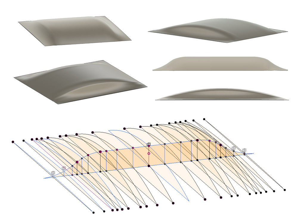 Roof Details Roof Details by ed cloutman, on Flickr |
|
|
|
Post by Roger on Jan 15, 2019 19:01:42 GMT
Hi Ed,
That looks pretty good to me. It's tedious, but it does work. On Alibre you can project sketches from another and maintain the relationship between them so you can make changes on one and have that reflected on the other. I presume that's what you've done for identical sketches either side of the centre line?
Am I right in thinking this is just the centre section which is riveted to the outer plate? I notice that it's made in two halves which are riveted together in fill size. I take it you're planning to form it as one piece since you've modelled it all, but I guess you could make it in two halves which might be easier to form.
|
|
|
|
Post by terrier060 on Jan 16, 2019 11:17:57 GMT
No Roger - I think the roof would have originally been made in one piece. It was the restoration that they did in this way just as they manufactured the base of the chimney by slitting the base all round and filling in welded metal sheets.
|
|
|
|
Post by GeorgeRay on Jan 16, 2019 18:23:10 GMT
Ed
The roofs were originally made in two pieces as were all of Stroudley locomotive roofs tank or tender. There is both photographic and drawing evidence of that.
George
|
|
|
|
Post by terrier060 on Jan 17, 2019 10:48:27 GMT
Yes I realise that George - we are talking about the rivets around the edge on the photo above. From my drawings the curve extended right to the edge of the guttering, even though it was in two halves.
What is the evidence that the roof was in two halves, by the way? I am sure they all have been replaced many times in the last 120 years. The strip over the middle could just have been a stiffening piece to stop droning, and it has been assumed that this was a join. Surely the logical thing would have been to make it in one piece unless it can be explained there was a particular reason for making it in two halves?
|
|
|
|
Post by terrier060 on Jan 18, 2019 17:30:10 GMT
OK I have been doing some thinking and to do the windows the proper way would require 16BA threads, which is watchmaking as the diagram shows. I would also have to make 128 of them which would be daunting to say the least! I think I will have to take a similar approach to Jim and Julian, but I will solder or glue the inside brass bezel to the spectacle plate. I can then tap the inside bezel and spectacle plate 12BA and use short plug screws on the inside bezel and long screws on the outside with clearance holes through the outside bezel. Does anyone know where to get brass dome-head 12BA screws, or does one have to make them! 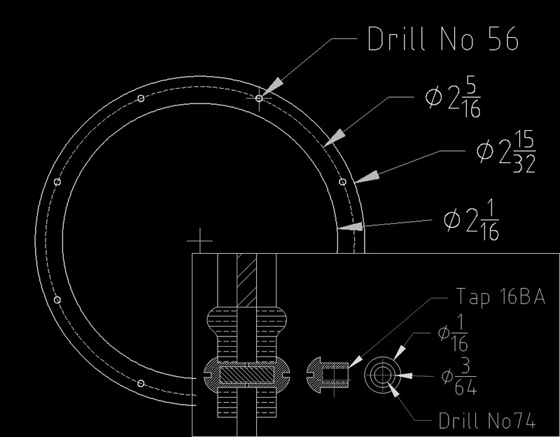 Window detail Window detail by ed cloutman, on Flickr |
|