stevep
Elder Statesman

Posts: 1,070
|
Post by stevep on Jan 18, 2019 18:22:09 GMT
|
|
weary
Part of the e-furniture

Posts: 290
|
Post by weary on Jan 18, 2019 18:26:46 GMT
.
|
|
|
|
Post by terrier060 on Jan 18, 2019 23:54:17 GMT
Thanks Steve - they only appear to do round head so I suppose I will just have to modify them to dome head. Ed |
|
jma1009
Elder Statesman
Posts: 5,901
|
Post by jma1009 on Jan 19, 2019 0:20:43 GMT
Hi Ed,
I don't know what you are on about here. The spectacle glasses were held into position by screws by the frames tapped on one side and a clearance hole into the other plus through the cab spectacle sheet. If you widened your research to consider all the preserved Terriers this would be clear! You also contradict what F.C. Hambleton showed in his drawings which Jim sent you, and which you posted a few days ago.
If you don't believe me have a look at 'Gladstone' that hasn't been mucked about with since 1929, and 'Como' in Brighton Museum! Or W11 'Newport' ex 'Brighton', not forgetting dear old Stepney!
Cheers,
Julian
|
|
|
|
Post by terrier060 on Jan 19, 2019 19:00:07 GMT
Actually Fenchurch's are fixed with what looks like aluminium pop-rivets!! But there are at least eight of them! Stepney and Boxhill have both been altered and have three screws holding the outside bezel and eight on the inside. I can't speak for Newport as I have not seen the engine. The problem with Jim's sketch is that scale bezels are very thin, even at my scale, and with clearance holes in the outer bezel and the spectacle plate, there would not be much thread to hold it all together - hence fixing the inside bezel to the cab with the front one removable to replace the glass should it be necessary.
|
|
|
|
Post by terrier060 on Jan 19, 2019 21:00:58 GMT
Hi Ed I found this reference to a 'Stroudley Cab Window' in an old publication. Not necessarily from a Terrier but it may be relevant. From other photos there are eight screws fitted from inside the cab, ie round-head with slot. On the outside there is a corresponding dome which may be a tapped insert or might just be the end of the screw with a rounded profile. It doesn't appear to have a screwdriver slot though. I would imagine that the three screws inserted from the outside on 'Boxhill' and spaced between the others, is a later mod when the eight 'screw ends' in this case seem to be finished off flush or the holes filled.
What I have done with mine is tap the outer glass retainer 12BA with clearance holes in the inner retainer, the screws will be finished to length with the ends rounded to suit. Jim  Hi Jim - from what I can see from your photos of your cab, you seem to have screws on both the inside and outside bezels rather than the diagram shown here. Is that correct? |
|
|
|
Post by Jim Scott on Jan 19, 2019 23:28:54 GMT
Hi Ed The screws were put in as per F C Hambleton's drawing, from the inside only and screwed into the outer bezel. Somewhat over size at 12BA but I don't remember having any issues with the thread depth. What you may see from a photo are the slightly protruding threads, which I will round off or finish flush after the cab is finally painted. I don't know what the arrangement is on 'Boxhill', other than there are definitely three screws through the outer bezel which are offset from those inside the cab.
Jim
|
|
|
|
Post by terrier060 on Jan 20, 2019 1:04:08 GMT
Yes Jim, both Boxhill and Stepney have different pitches inside and out. Three on the outside with one at the top, and eight inside as per the original drawings. Incidentally, if you look closely there are dimples at the centres of the eight holes on the outside, presumably in the casting, but they decided not to use them. In Fenchurch they have used pop-rivets, I assume for speed of assembly during refurbishment.
I suspect it is impossible to get countersunk 12BA screws with shallow dome heads, so will probably have to modify some round-head screws.
Will probably do as you have done, but to give a longer thread I will fix the inside bezel to the spectacle plate and screw from the outside where the screws will show more. Was there any reason you chose to put the screws on the inside?
All good fun!
Ed
|
|
|
|
Post by terrier060 on Jan 20, 2019 11:07:22 GMT
My apologies to all (including Julian). I have had a really close look at the photos and what I thought were rivets on Fenchurch are actually small nuts on the inside bezel which look as if they have been soldered on to give extra strength to the thin bezel. The outside bezel has countersunk screws. On Stepney, there are what looks like round head screws on the inside to a threaded bezel on the outside. But the outside bezel also has three round head screws. Boxhill is the same as Stepney, except that there are only three holes in the outside bezel so the inside screws do not appear to go in to it. the latter is held on by three round head screws.
So it looks as if many different methods were used and one can take ones pick. This level of detail may seem unimportant to some, but when one spends a long time preparing the drawings it makes one concentrate on the small details.
Ed
|
|
mbrown
Elder Statesman
Posts: 1,719
|
Post by mbrown on Jan 20, 2019 15:04:44 GMT
Just a guess, but might the three small screws be there to make it easier to assemble when you can't get your hands around the cab to work on both sides at once.... i.e. lightly screw one bezel on with the three small screws and then get around to the other side to put the "proper" fastenings in through all three layers?
I suppose the alternative is to have an intelligent mate on the other side, but still it wouldn't be easy to get all the holes lined up until a couple of screws are in.
As I say, just a guess...
Malcolm
|
|
|
|
Post by terrier060 on Jan 20, 2019 20:46:28 GMT
That is what I call good lateral thinking Malcolm.
|
|
jma1009
Elder Statesman
Posts: 5,901
|
Post by jma1009 on Jan 20, 2019 21:07:25 GMT
Stroudley would not have any screw slots showing on the outside of his locos, whether it be the humble Terriers, or Grosvenor, or Abergavenny, or Gladstone!
What bodges and repairs were carried out many years later is quite a separate matter!
My pics of Boxhall at Clapham show 8 round head screws with the heads all on the inside of the cab. Having seen Stroudley cab spectacle frames myself (LBSC owned one!) and Newport (ex Brighton) on the IOWSR, I am not in any doubt as to how the original cab spectacle rims were affixed.
Cheers,
Julian
|
|
|
|
Post by terrier060 on Jan 20, 2019 23:35:52 GMT
Point taken Sir.
|
|
|
|
Post by terrier060 on Jan 21, 2019 12:18:36 GMT
Good morning all. Today is the first day that I have really felt like going into the workshop since Christmas. I think I am getting over the bug at last, but just when you think it has gone, another coughing fit returns! But rather than spend more time talking about windows, I thought it was time to tackle some metal-cutting. One thing I have always hated doing is marking-out, particularly when there are a lot of small holes. CNC is bliss when it comes to fiddly work. One can draw it on the PC as large as you like and then the machine copies it to the thousandth of a inch, repeatedly. It is still a bit nerve-racking. I tend to leave the workshop rather than hear all those strange noises emanating from the Tormach. I can get on with more drawing. So the front of the cab is now cut out and awaits the glass and bezels. After much discussion I shall be screwing from the inside into the outside bezel, but will fix the outside bezel to the spectacle plate either with solder or adhesive. This will strengthen the plate as the brass is quite soft. I've no doubt it will age-harden in time. I am not sure whether I shall machine down some brass angle, or bend my own from some 26SWG brass that I have lying around. 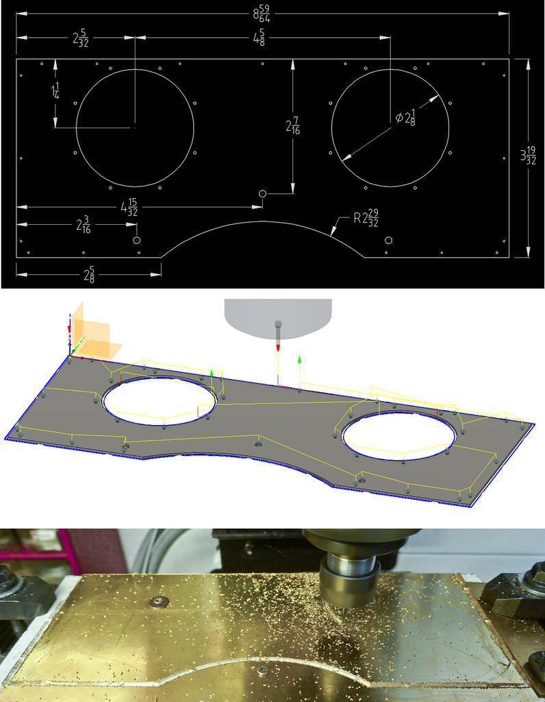 Front spectacle plate CNC Front spectacle plate CNC by ed cloutman, on Flickr 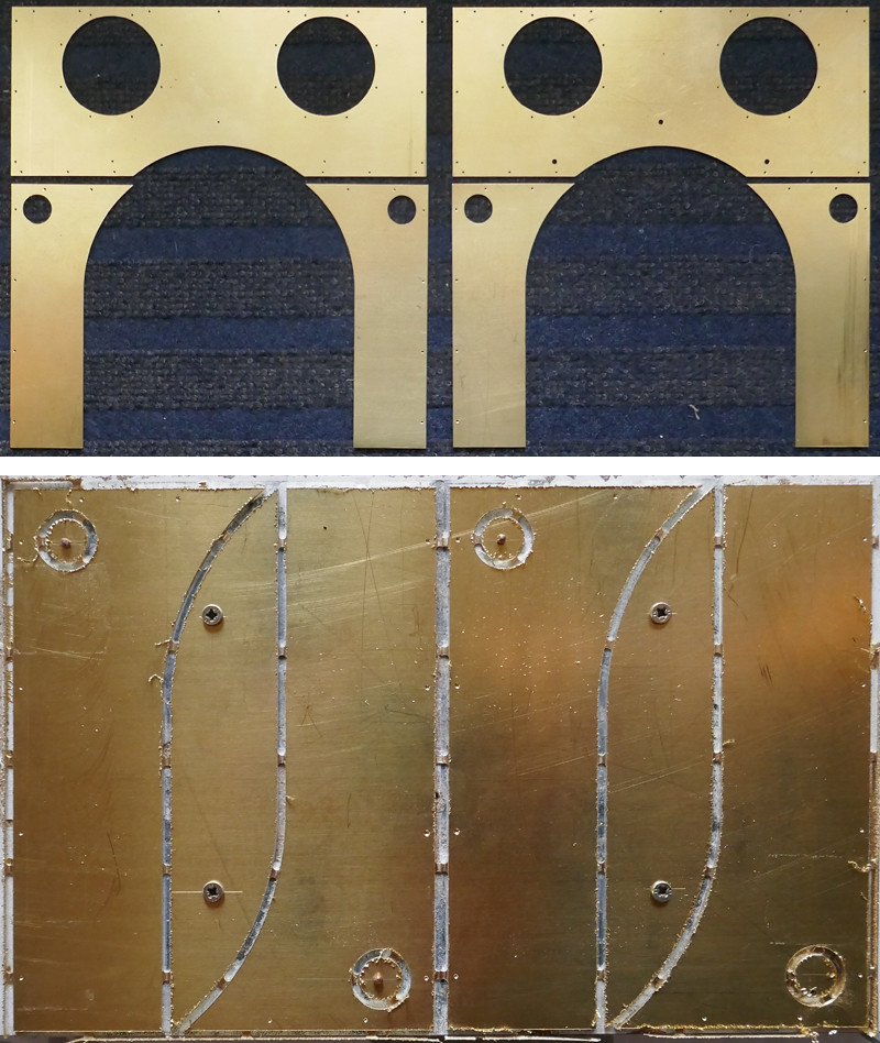 Cab front Cab front by ed cloutman, on Flickr |
|
|
|
Post by Roger on Jan 21, 2019 12:38:13 GMT
Hi Ed,
That's come out very well indeed. Looking at the nibs, it looks like you're using a near vertical plunge, but that might be just the way the photo was taken. If they are, I'd suggest making them the same as the usual sloping entry. I reckon the distance you have between them is just about right.
I always use a roughing and a finishing pass on sheet metal work, I find it gives a better finish to the edge with less marking where the nibs are. Of course, you do need to make sure the nibs are defined in exactly the same position.
|
|
|
|
Post by terrier060 on Jan 21, 2019 22:07:01 GMT
Thanks Roger - yes I have used sloping nibs as you suggested - it must be the photo. It was a bit shallow in places - the brass does not lie completely flat, but I am quite handy with a piercing saw from my clock restoration days, so make quick work of it. The cutter has been running quite sweetly and no sign of needing changing. It is a 2mm diameter cutter from China so I have no idea what it is made of. It is not blued like many are. I run it at 4600rpm and 1.6 in/min and take cuts of 10 thou. I think I could use a faster feed, but like you say best be steady. I get quite decent sized chips so I don't think there is any fear of it rubbing. There seems no problem with the high rpm with this brass. 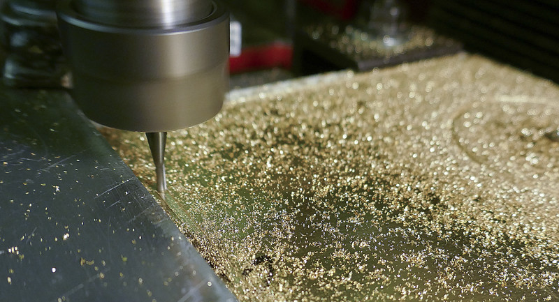 Chips Chips by ed cloutman, on Flickr |
|
|
|
Post by terrier060 on Jan 22, 2019 12:43:55 GMT
Sadly the cutter just broke after doing half of the sheets. I found that I had forgotten to change the feeds on the new piece I was making and it was going through at 2.6 in.min and 20 thou cut instead of 1.6 in/min at 10 thou cut. So I lost my beautiful end mill which was still cutting sweetly. The new one is nothing like as good so I am a bit miffed. I think the good one was K2 coated from Cutwel and it was quite expensive but designed to cut dry. I will try another one and see. If so it was well worth extra expense.
|
|
|
|
Post by David on Jan 22, 2019 20:50:32 GMT
Is this still engraving brass you're using? You said the brass isn't laying flat, do you hear it making odd noises when cutting the bits that aren't flat? I'd expect the nibs to be almost non-existent where it isn't flat on the base.
It's a shame about that first cutter - it sounded like a good one! At least you know what to buy for this material.
Those are much bigger parts than I've cut yet and they look good.
|
|
|
|
Post by terrier060 on Jan 23, 2019 16:07:25 GMT
Hi David - no, not engraving brass, nasty sticky half-hard brass. I am going to take Roger's advice and start with a much slower feed and rpm. It was stupid not to have taken notice which cutter I was using - but I have bought off so many suppliers - Cutwel, Rennie, E W Equipment and a load of Chinese imports, and they have all got similar packing and due to my laziness have all got mixed up.
The Tormach 440 is just about big enough to do most of the cutting out in 7.25" gauge as most of the cab is broken down into smaller units which are riveted together. I may have to use the large mill for the tanks, which I shall make from thicker brass.
I have just this morning bought the 2.5" diameter brass rod for the bezels. I will make up a forming tool to get the curve on the bezels the same on all eight of them. There also needs to be slight clearance for the circular glass windows.
|
|
|
|
Post by Roger on Jan 23, 2019 16:21:55 GMT
Maybe this is a good opportunity to figure out the way to machine forming tools on the Tormach from Gauge Plate so that you machine them at the front clearance angle, corrected for the fact that they will be used flat on the lathe. You only have to figure it out once and then you can use the same method each time.
I made a wedge shaped support to sit the Gauge Plate on in the vice to give the right front clearance angle without having to measure it each time with the Vernier Protractor.
This uses the idea of an open sketch for machining, like we spoke about on the phone recently.
|
|


