|
|
Post by Roger on Feb 19, 2018 20:02:52 GMT
Looks great Ed, well worth all that sweat and toil!
|
|
|
|
Post by terrier060 on Feb 20, 2018 11:25:28 GMT
Thanks Roger - and for the rivet info - much obliged. I was playing with the 'Terrier' this morning to take my mind off making the rest of the springs, and was oiling the motion etc. I thought some of you might be interested in how I have overcome lubricating the inside cranks and eccentrics. 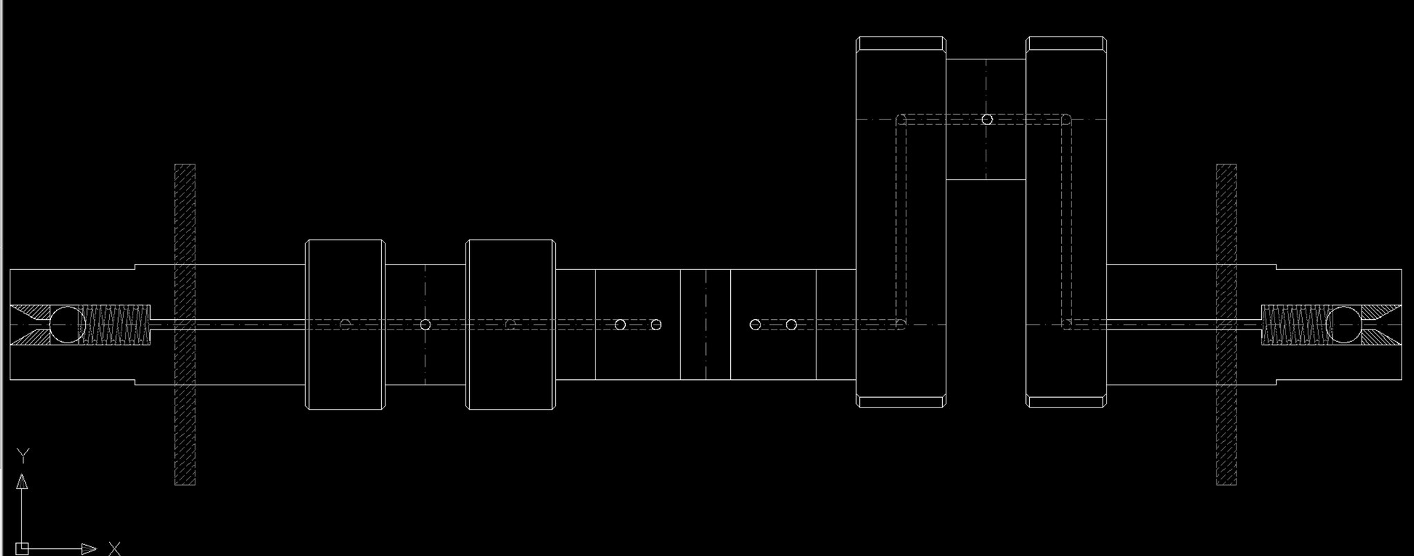 Centre wheel oilways Centre wheel oilways by Ed Cloutman, on Flickr What I have done is drilled a 1/4" hole in the axle and made an oil chamber sealed with a stainless ball and spring. Then I drilled a 1/16" hole through the whole crank and crank webs. Obviously there is some plugging to do! The great thing about this is that the long hole acts as an oil reservoir and the centrifugal forces send the oil to where it needs to be - to the eccentrics and the big-end journals. The same thing is repeated at the other end. Once the drilling and plugging is complete, the axle can be centre-drilled and the wheels quartered and pressed on. It might seem a lot of work, but it is easier to do than describe and means that a squirt with an oilcan every so often through the centre hole of the driving wheel is all that is required. |
|
|
|
Post by Cro on Feb 20, 2018 11:41:38 GMT
Ed I've seen and used this trick many a time for oiling the axles in the boxes but never for a whole crank axle, genius! Also the springs look great.
Adam
|
|
|
|
Post by terrier060 on Feb 20, 2018 17:11:35 GMT
Thanks Adam - I do have oil boxes as per Stroudley on the eccentrics and big ends, and if you pump hard enough oil will come out of the top of them. The axleboxes are enclosed as per full-size to prevent ingress of dirt. They have large oil reservoirs in the top which are fed from brass oil boxes mounted on the chassis and water tanks. The oil boxes also oil the valve spindles. The slide bars and valve guides have their own boxes which are easy to reach under the front part of the boiler. 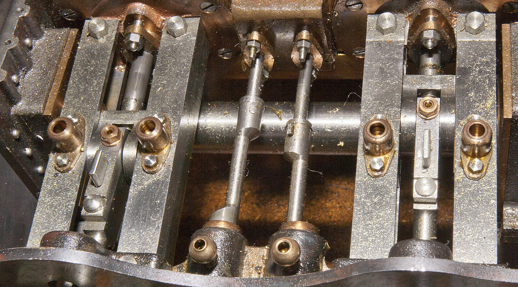 A1X valve gear A1X valve gear by Ed Cloutman, on Flickr 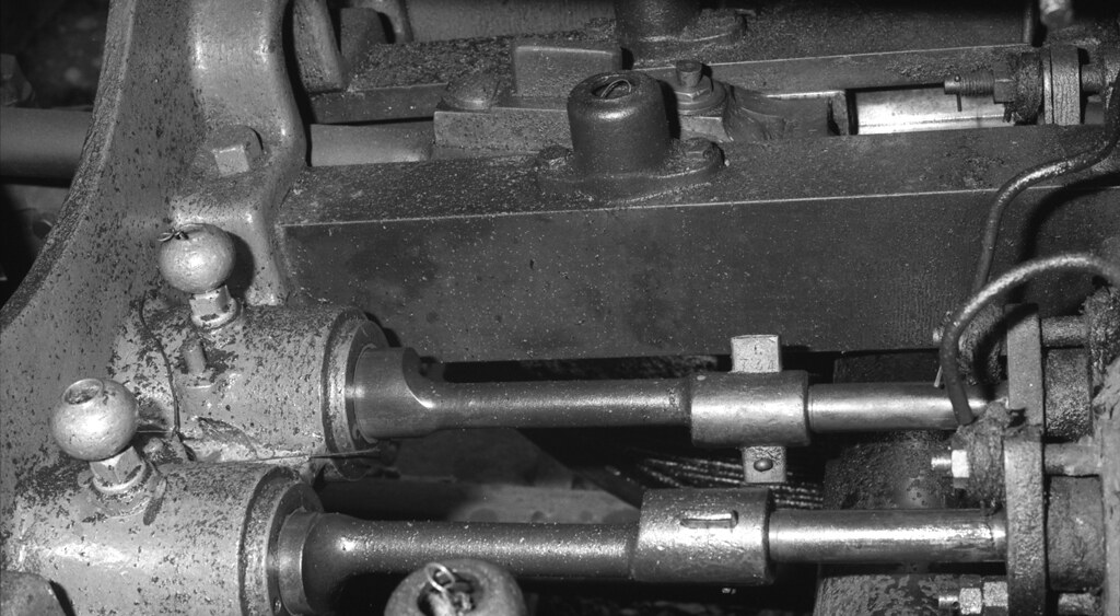 Fenchurch 036 Fenchurch 036 by Ed Cloutman, on Flickr |
|
|
|
Post by Roger on Feb 20, 2018 17:27:25 GMT
Thanks Roger - and for the rivet info - much obliged. I was playing with the 'Terrier' this morning to take my mind off making the rest of the springs, and was oiling the motion etc. I thought some of you might be interested in how I have overcome lubricating the inside cranks and eccentrics. Centre wheel oilways by Ed Cloutman, on Flickr What I have done is drilled a 1/4" hole in the axle and made an oil chamber sealed with a stainless ball and spring. Then I drilled a 1/16" hole through the whole crank and crank webs. Obviously there is some plugging to do! The great thing about this is that the long hole acts as an oil reservoir and the centrifugal forces send the oil to where it needs to be - to the eccentrics and the big-end journals. The same thing is repeated at the other end. Once the drilling and plugging is complete, the axle can be centre-drilled and the wheels quartered and pressed on. It might seem a lot of work, but it is easier to do than describe and means that a squirt with an oilcan every so often through the centre hole of the driving wheel is all that is required. Hi Ed, I really like this solution, I've never liked the idea that oil would drain back and dribble out of the hole in the shaft. It's far better to make sure that what you put in ends up in the bearings instead. What are you going to use for the ball and seat to get a seal? An 'O' ring in there might be another option. |
|
|
|
Post by suctionhose on Feb 20, 2018 22:59:34 GMT
Never seen it "drain back". no ball and spring. just centre drilled axle. Been oiling axles this way since 1975.
Ed, the motion, oil cups etc are just lovely!
|
|
|
|
Post by terrier060 on Feb 21, 2018 12:03:01 GMT
Thanks Ross. I hope to go to the Bluebell in April to take some more measurements so that I can get the break gear on the A1X finished. I will be posting an update on the springs soon. I have finished the top fittings of the hangers though I have had to remake one due to a stupid error which I put down to old age! Now starting on the bottom fitting and then on with the other 10 springs.
Ed
|
|
|
|
Post by terrier060 on Feb 22, 2018 11:02:43 GMT
First one in place - only another 11 to go! What I didn't expect is that they actually work! I thought they would be solid. They are much too stiff, but combined with the coil springs they should act as shock absorbers. 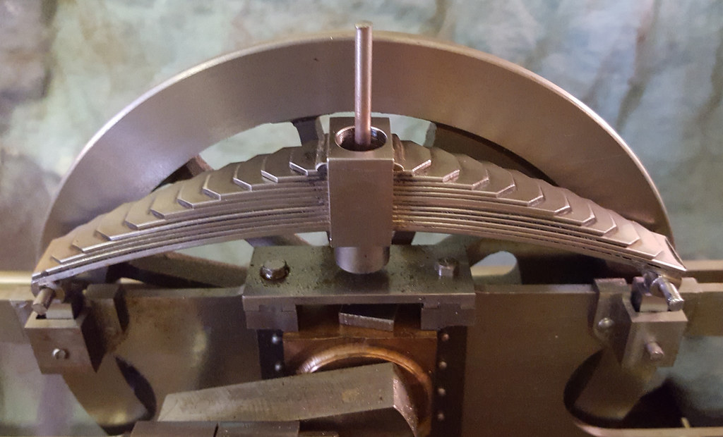 Driving spring 01 Driving spring 01 by Ed Cloutman, on Flickr |
|
|
|
Post by terrier060 on Feb 22, 2018 21:30:00 GMT
|
|
|
|
Post by 92220 on Feb 23, 2018 17:08:20 GMT
That oilway is a very clever solution Ed, and as Adam says, those springs look good too.
Bob.
|
|
|
|
Post by terrier060 on Feb 23, 2018 18:11:26 GMT
Thanks Bob. I was surprised that there was any spring in them, as although they are scale thickness, they are mild steel. The coil spring allows finer and easier adjustment and a softer ride.
Martin Evans says that the springs were painted yellow ochre with black buckles. I cannot see them mentioned in your excellent drawings, which I shall follow in due course. Painting precludes the use of Tufnell which does not really look right in any case. I suspect the A1X springs are not painted?
As an aside, does anyone provide transfers for the lining and lettering of the 7.25"G version? Julian will probably know as he is well up on Don Young's 'Newport'.
Ed
|
|
|
|
Post by Cro on Feb 23, 2018 22:16:02 GMT
Ed, the guys at steam workshop did a great video of how to do gold leaf lettering on some boxhill tanks in 5" I will try find the video for you.
Adam
|
|
|
|
Post by Jim Scott on Feb 24, 2018 9:49:06 GMT
Ed, the guys at steam workshop did a great video of how to do gold leaf lettering on some boxhill tanks in 5" I will try find the video for you. Adam Hi Adam Steam Workshop Video at www.youtube.com/watch?v=-i7_1D_FkzAAll 'Terrier' builders need to bookmark this. Jim S ps The construction of this loco, basically Martin Evan's 'Boxhill', was covered in ME. modelengineeringwebsite.com/Styx_7.html |
|
|
|
Post by terrier060 on Feb 24, 2018 11:43:09 GMT
Thanks all of you - that is a great video. I just don't think I am capable of such fine work - my hand shakes too much even if supported. I may have to admit defeat with lining and lettering and let a pro do it for fear of ruining a good model. See what I feel like in a few years time!
Incidentally I got side-tracked again today and thought I would see what the wheel weight were on the locos. It was a very crude test as the cab and chimneys are missing, but I thought I would try anyway. As it is an 0-6-0 all I did was first lift the front wheels on to our bathroom scales and then the rear wheels. The side tanks fall roughly over the centre wheels so I ignored them. The results were:
Front: 24.7kg
Rear: 18kg
So I tried putting weight where the coal bunker will be and it required about 3 to 4kg.
The hydrostatic oil tank and accessories will add a bit of weight. I may even make the rear bunker into a water tank for the injector (if I fit one on the A1). Interesting that the early 'Terrier' drivers had to find a convenient stretch of line to run up and down if the water level in the boiler got low!
Ed
|
|
|
|
Post by terrier060 on Apr 7, 2018 18:38:57 GMT
I have been away doing other things, but spent a very happy day at the Bluebell Railway who I would like to thank for making it possible for me to take measurements of 'Fenchurch' and 'Stepney'. It was raining all the way from South Wales to Hayward's Heath, but Thursday was a beautifully sunny day which brought the crowds out. I was able to achieve all the photos and measurements that I set out to take and would like to personally thank all the staff who made my visit so enjoyable. If you have never been to the Railway, I really urge you to go as you will not be disappointed. The line runs through beautiful English countryside and we saw all manner of wildlife including buzzards, rabbits, pigs, pheasants, blackthorn now beautiful with it's white blossom, and celandine, it's yellow flowers carpeting the woodland. So now I have no excuse, because I have the important measurements I required of the A1X smokebox and chimney and the cast-iron brake gear. I also took copious photos of the underside of the running plates, bits that most people never see. On the way home on Friday I went via Roger Froud's and spent three hours in his company. I was not disappointed. He really is a master of CNC and perfection to detail, but like me hates rivet-counters! I got the impression, like me, he does his best to make his locomotive look right, run right and is there firstly to please himself, not others. I hope I have got that right Roger! It took me seven hours to drive home - normally a four hour journey. I was fighting grid-lock as it was a Friday and I think it coincided with the end of the Easter holidays. It was not a pleasant experience. Incidentally, unless my tape measure has stretched, the diameter of the A1X smokebox is exactly the same as the A1 and the door is also the same diameter give or take 1 inch! 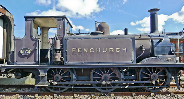 Fenchurch Fenchurch by Ed Cloutman, on Flickr 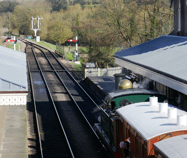 Sheffield Park 01 Sheffield Park 01 by Ed Cloutman, on Flickr  Sheffield Park 02 Sheffield Park 02 by Ed Cloutman, on Flickr |
|
|
|
Post by terrier060 on Apr 10, 2018 17:38:15 GMT
Having visited Roger and seeing his setup I am getting more and more tempted by the conversion to CNC. I spend a lot of time reducing the full-size drawings to 7.25G in CAD, so learning and converting to CNC should prove beneficial and time-saving. Also I would not be spending hours manually operating the mill, so could be getting on with other things. In any case going on to CNC would be a new challenge and I like that! I get bored very quickly and have tried lots of things including DCC OO-gauge, and various electronic projects and lots of other silly things, but once I have completed them to my satisfaction, I enjoy trying something new. The old adage applies "Jack-of-all-trades, Master-of-non"!! There are always going to be people out there MUCH better than me, but that is good because they can give one the expert advice when it is required. So Roger here are a few stats of my mill so that you can judge whether it would be man enough to take the direct drive motors you use: 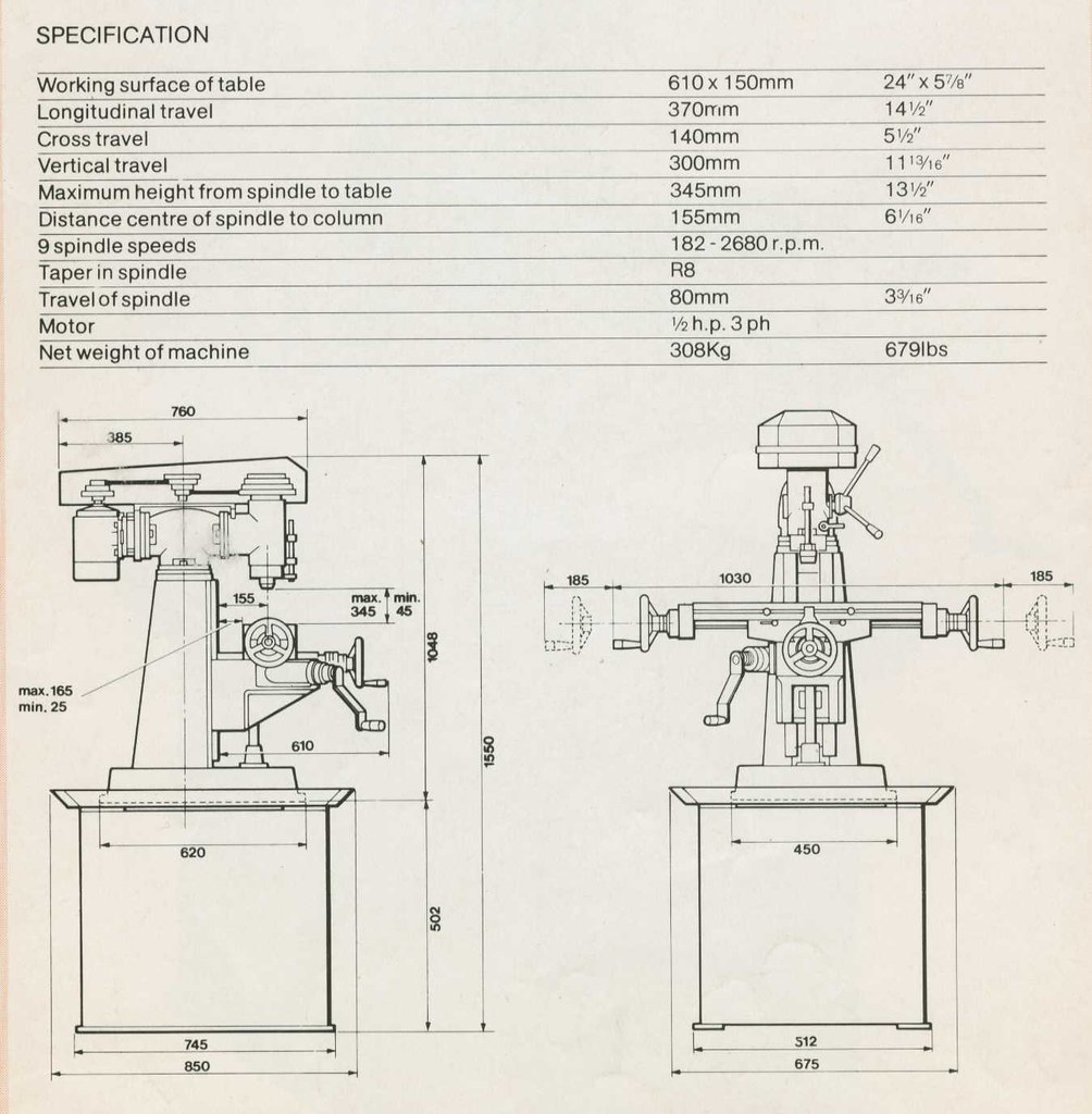 Notebook117 Notebook117 by Ed Cloutman, on Flickr |
|
|
|
Post by terrier060 on Apr 10, 2018 18:12:10 GMT
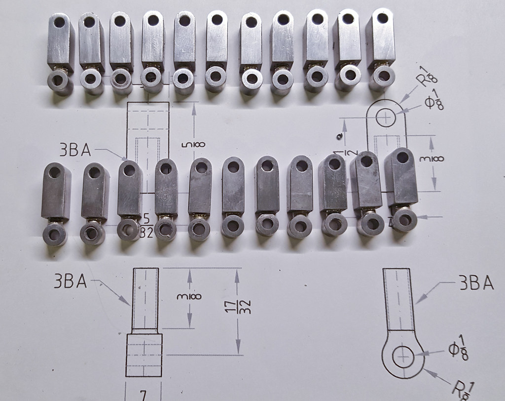
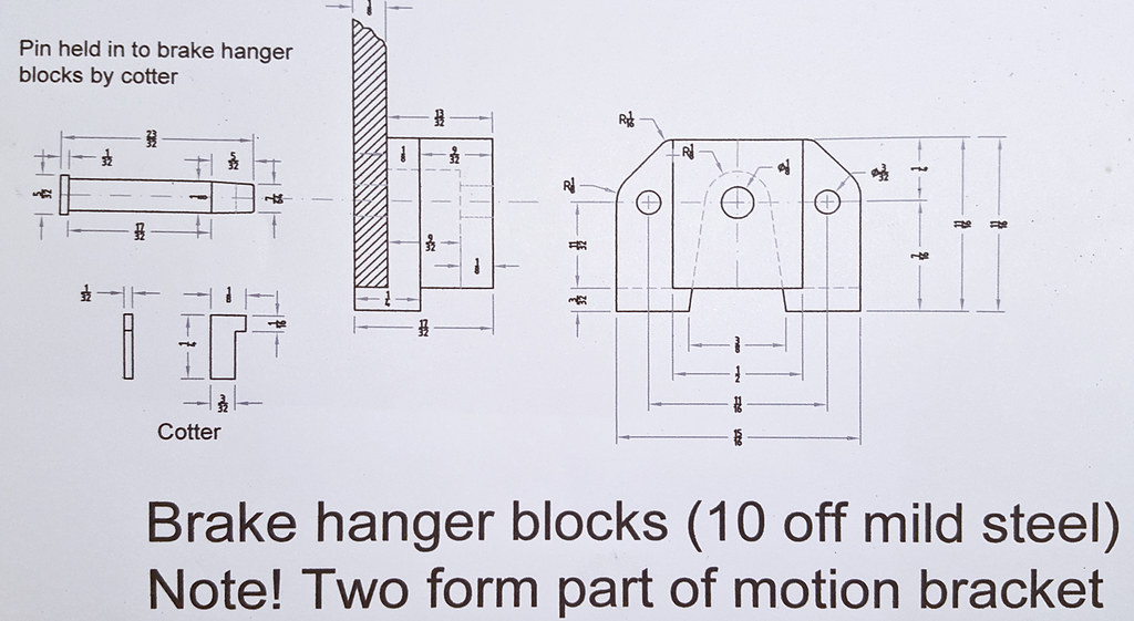
I have been getting all my drawings sorted, following my visit to the Bluebell, and can now go forward with the smokeboxes and A1X brake gear. I start with the rough sketches made at the Bluebell, then turn them into scaled drawings. The red figures are the scale conversions using my little conversion program. 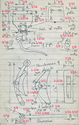 Notebook109 Notebook109 by Ed Cloutman, on Flickr 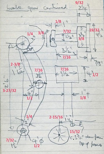 Notebook112 Notebook112 by Ed Cloutman, on Flickr 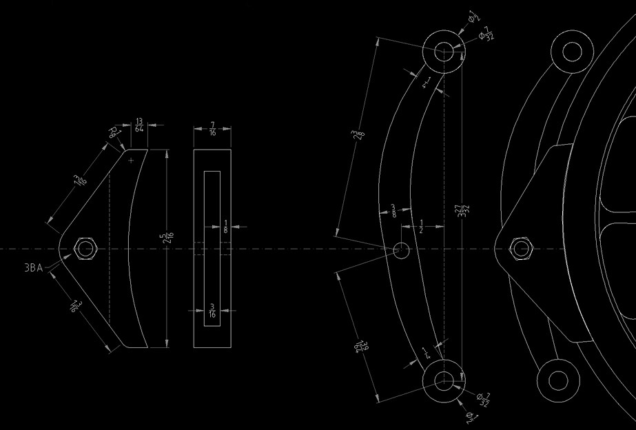 Brake details Brake details by Ed Cloutman, on Flickr book112 by Ed Cloutman, on Flickr Now to get back into the workshop! |
|
|
|
Post by Roger on Apr 10, 2018 19:43:11 GMT
Having visited Roger and seeing his setup I am getting more and more tempted by the conversion to CNC. I spend a lot of time reducing the full-size drawings to 7.25G in CAD, so learning and converting to CNC should prove beneficial and time-saving. Also I would not be spending hours manually operating the mill, so could be getting on with other things. In any case going on to CNC would be a new challenge and I like that! I get bored very quickly and have tried lots of things including DCC OO-gauge, and various electronic projects and lots of other silly things, but once I have completed them to my satisfaction, I enjoy trying something new. The old adage applies "Jack-of-all-trades, Master-of-non"!! There are always going to be people out there MUCH better than me, but that is good because they can give one the expert advice when it is required. So Roger here are a few stats of my mill so that you can judge whether it would be man enough to take the direct drive motors you use: Notebook117 by Ed Cloutman, on Flickr Hi Ed, Your comments about your character could have been written about me. Still, it's probably more useful to be reasonably proficient at a larger number of useful things than to be brilliant at only one. At least, that's my excuse. I think your machine is an eminently suitable candidate for a CNC conversion. I'll have to put a tape measure over my machine to see if it's the same size. Judging by the travel, I'd say it's a little smaller. One thing you might consider is to direct drive the knee leadscrew from underneath ie with the motor protruding into the cabinet. Mine drives from the top which means the Servo motor drives it through a toothed belt which also has a 2:1 reduction. I can't guarantee that you'd get away with a direct drive, there's no counterbalance, but you might well do since your knee arrangement is probably lighter than mine. At least if you needed a reduction, it would be relatively straightforward to do that there, there's plenty of space. One thing to note about the Z-axis is that you need a Servo motor with an integral mechanical brake. The SureServo amplifier controls that through an extra pair of wires and it's seamless in operation. Without it, the knee sinks under its own weight when the Servo is disabled. Ball leadscrews are rolling contact bearings, so they can drive in reverse, unlike conventional threads with a fine pitch. I was told on CNC forums that you definitely need to counterbalance the knee with springs or Gas Struts, but that proved to be another case of 'opinion dressed up as fact'. I decided to try it anyway and add a counterbalance only if it was necessary. It wasn't. I do think you'd need to add a spacer in the column if you don't already have one. Making one for mine is one of the best decisions I made. If that's a single phase motor, you could dispense with variable speed control and just turn it on and off with a relay. Personally I'd change it for a universal 220v 3-phase motor and buy a cheap drive for it. It's so useful to be able to adjust the speed in the program and override it at will while you're cutting. |
|
jma1009
Elder Statesman

Posts: 5,900
|
Post by jma1009 on Apr 10, 2018 20:31:43 GMT
Hi Ed,
What wonderful sketches you have done! I have looked at these (as well as your superb CAD drawings) because they have the fullsize dimensions which I can use for 5"g, 1.062" to 1ft scale.
Your pics of the details would also be of considerable interest.
Cheers,
Julian
|
|
|
|
Post by terrier060 on Apr 10, 2018 22:38:16 GMT
Hi Julian
Anything I can help with I shall be only too pleased. I can easily convert the measurements to any scale. I use an exact scale for 7.25G (7.7931:1), which makes a slightly larger locomotive. As you well know 'Terriers' have been constantly messed about with, so I am just trying to get a sensible level of detail without going overboard. I do like my measurements to be as accurate as I can of the full-size, which is why I gave up using other peoples drawings long ago. They make too many 'convenient' adjustments. When it comes to valve gear and cylinders I use exact measurements to the nearest thou if required. This seems to have paid off as the engine runs pretty nearly in mid-gear. Probably will on steam! I do have a lot of photos so send me a list and I will see what I have.
Ed
|
|