|
|
Post by greenbat on Jan 5, 2019 12:36:19 GMT
Morning all,
I'm about to start making axleboxes for the front bogie of my 5" gauge Stirling single. I have seen some boxes that have the insides of the axlebox flanges radiussed, so that if one wheel lifts higher than the other they won't jam up. This is shown on page 25 of my copy of Manual of Model Steam Locomotive Construction.
Is there a proper way of working out what this radius should be?
|
|
|
|
Post by Roger on Jan 5, 2019 12:56:51 GMT
I don't know why axles boxes are drawn parallel since this is clearly wrong. Personally, I think this may as well get machined when the sides are done.
You have to decide what your end float on each axle is going to be before going too far. On my 0-6-0, it was suggested that the middle wheels should have a minimum of end float, with more at the front and rear axles. These clearances will be reduced as the axle lifts on one side.
You can 3D model the axle, axle boxes and horns to see the effects of all of this, or used 2D CAD or paper drawings to figure out what's going on. The angle will also affect the bottom of the axle box which on my build with coil springs, means you have to elongate the slots in the horn keeps where they pass through.
|
|
|
|
Post by Deleted on Jan 5, 2019 13:01:33 GMT
Hi, I'm about to tackle this on my loco's main axleboxes, there is no dimension given on the drawings. I intend to set the axlebox up on a centrally drawn line and then using a compass trace an arc that just brushes the center of the slot until it takes off an amount on the ends that matches what's shown on the drawing (I can then measure this arc on a rule), I suspect the arc will be smaller than one may think. Hopefully, I'll get around to this in the next week or so. When I radiused the axleboxes for the tender I wasn't so picky as they are free running from each other (ie no rods connecting them) and did these by hand until there was enough lift on each side of the axle. the important thing is not to remove any material from the middle of the slot or you may upset the axle distances.
Pete
|
|
|
|
Post by delaplume on Jan 5, 2019 19:37:14 GMT
Hello all,
There is a school of thought that asks}----- "Why do you need those inner flanges anyway?"....
When working as a contractor at the SVR we used to off-set the axlebox in the vertical miller by placing 2 mechanical hacksaw blades between the box and the vice edge at the one end---thus slewing the box a wee bit...
With scale models the problem is that our locos run on "Real-time" tracks ie}--- those are real 1/4" drops between rails so our suspension etc, has to be set up for that situation.....This includes the relief for the flanges...
As a rule of thumb try this}---- using the height of the flange then the top and bottom 1/4 of that height be relieved by approx 15 thou ( 1/64 inch )...as a maximum trailing to zero when meeting the centre sections, which stay parallel and to size...
|
|
|
|
Post by builder01 on Jan 6, 2019 1:06:03 GMT
The radius of the flange on the axle box should equal the distance between the outside faces of the horn blocks. On a 5" gauge loco, this will be about 4-3/8". Measure yours to see what it is. This radius is not critical, but, the flanges should be relieved somewhat so they don't bind on uneven track. My loco is set up to run on 4-3/4" track, so the radius is 4-1/8". My wheels and suspension work just fine using this method of figuring out the radius. I machined this radius on my flanges using a vice clamped to a rotary table. The axle block must be centered so the radius is the same above and below the center line of the block, assuming your axles are in the center of the block. You can see in the photo that the layout dye shows how much material has been removed. Leave just a little of material at full size toward the center of the block. 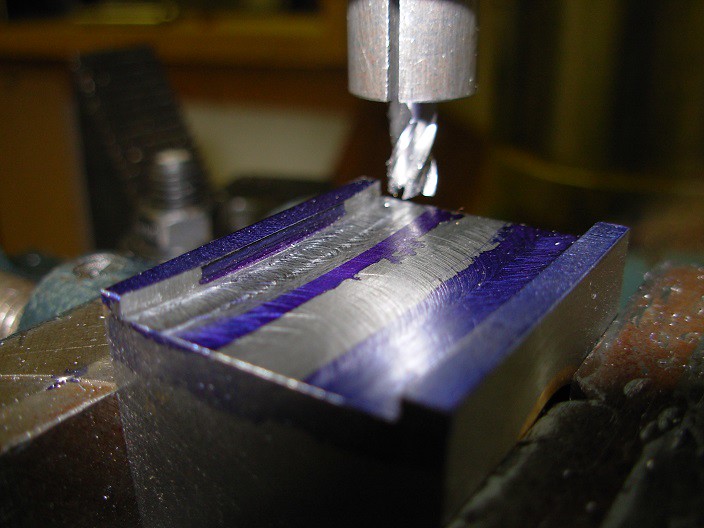 DSCN0745 - reduced DSCN0745 - reduced by Builder16, on Flickr |
|
|
|
Post by suctionhose on Jan 6, 2019 8:34:03 GMT
I usually machine those reliefs as a straight cut at a couple degrees on the swivel base vice. Set a stop. Put the axle boxes in one after the other. Swivel a couple of degrees the other way. Put them through. I wee file to ease as necessary. Very quick job.
|
|
|
|
Post by delaplume on Jan 6, 2019 11:24:28 GMT
Hello everyone, I've put a "like" for both Suctionhose and builder01 as they obtain the desired results via different approaches.......If you have already assembled your wheelset with "solid" type axleboxes you can still put a slight relief on the flanges by good old hand filing !! builder01's photo is very useful for you to gauge the amount to remove and the distance along the length of the flange you need to go.....This is what I was trying to explain in my convoluted way !!...LoL !! As stated the important thing is that some clearance is provided for --- one way or the other.. Anyone care to answer that question about the need for the "inner" flange  Alan |
|
mbrown
Elder Statesman

Posts: 1,719
|
Post by mbrown on Jan 6, 2019 12:13:28 GMT
LBSC rarely specified an inner flange on any of his 2.5"g locos - and, I think, often omitted it in 3.5"g too.
On the other hand, I don't know of any "full size" loco that doesn't have two flanges - and all my locos have two, just because the real ones do....
OK - I know that's not a sound engineering reason, but it's good enough for me!
Malcolm
|
|
|
|
Post by Deleted on Jan 6, 2019 12:29:26 GMT
IIRC there was a thread about this a few years back? I can't recall the outcome but I'm like Malcolm, I follow full size.
David, I'm interested in the info you give re 'arc' sizes? am I understanding this correctly, when you say 'measure the outside flanges of the horn faces' I'm assuming we are measuring across the frame width including the horns.. if so I can understand the reasoning/maths behind this, just wanted to check that I'm reading this correctly?
regards
Pete
|
|
|
|
Post by builder01 on Jan 6, 2019 13:26:50 GMT
Hi Pete,
Yes, you are understanding what I have said correctly. This distance seems to make sense to me as this is the face that the block will "roll" against. The above photo shows the beginning of the radius. I decided to call it "finished" when there was about 3/16" of the blue left un-machined.
David
|
|
|
|
Post by Deleted on Jan 6, 2019 13:34:13 GMT
Thank's David Hopefully, I'll be doing my own axleboxes by end of next week...fingers crossed..  cheers Pete |
|
oldnorton
Statesman
 5" gauge LMS enthusiast
Posts: 692
|
Post by oldnorton on Jan 6, 2019 14:26:06 GMT
I like builder01's proper way of doing it, but when I did the maths for mine it worked out at just 0.033" being taken off at the extremes of the flanges and I went for a simpler, and hopefully accurate removal.
I set the vice at 3.2 deg in the mill and removed 0.033" from the start of each flange, which left a land of 0.156" untouched in the middle. Just like Ross I eased the tiny transition with a Swiss file, and reasoned this was a quick way to make 24 cuts.
The axles are supposed to float by a defined amount in the boxes anyway (does this answer delaplume's need for the inner flanges?), so the few thou between a true radius and joined up flats does not seem too much to worry about.
Norm
|
|
|
|
Post by Roger on Jan 6, 2019 14:35:21 GMT
Just bear in mind that the longer that flat portion is in the middle, the more the axle box will be forced sideways even with a small angular displacement. Ideally, the whole flange should be curved with only the tangent touching so as to minimise this effect. As you can see from all the answers, geometrical ideals are not what's commonly used, simply because the angles are quite small and the clearances are large. I've gone for a very small flat at the level of the axle, and a tapered clearance above and below that.
|
|
|
|
Post by 92220 on Jan 6, 2019 15:43:52 GMT
I've just looked at the BR works axlebox drawing. It shows a VERY shallow curve. Almost imperceptible on the drawing. Unfortunately the liner is a separate detail and I don't have that one. However, the curve shown on the axlebox drawing is no way equivalent to the distance across the frames. It is much greater. Bear in mind that the wheels rarely move more than an inch or so on fullsize, under normal running conditions. There is also a gap between the axlebox face and the wheel face. Combining these two means that the actual curve required on the axlebox flange is a much greater radius than just the width across the frames. Think how much movement the axlebox will make while running. Not the total movement the axlebox can make, but what it does while running normally. That is the only time that there is any wear on the flange faces. What you need is relief at maximum up and down axlebox position, so that the boxes don't bind. The rest of the time the working clearances will cater for the tilting of the axle during running. After all, the bearing loads on our models are somewhat less than fullsize, though we are using similar metals. Fullsize ran millions of miles. Our models may, if they are lucky, run a few hundred.So as long as the axlebox cannot bind in the horn, at maximum angular deflection, that, really, is all that matters, and that there is adequate surface area in the normal running position.
Bob.
|
|
|
|
Post by greenbat on Jan 6, 2019 16:08:43 GMT
Thanks for the responses. I'm going to try putting ball bearings in the axleboxes on this model, so I thought that having the boxes double flanged would help with side loads. Messing about with 2D cad, it doesn't look like there's a geometrically correct profile for the outer flanges-though the inner flangelooks like it ought to be the between horns distance as a radius. I'll make them up parallel then see how much relief they need.
|
|
|
|
Post by Deleted on Jan 6, 2019 16:34:39 GMT
I don't have the works drawing for the main axle boxes on 4472, I do have a small image of U-325, the bogie axle box/horns...these are the same for a large variety of Gresley locos, it's not easy to read and you can't really enlarge it due to the poor resolution. This is just one of the many 'samples' that have appeared on the NRM website over the years. I haven't taken a lot of notice as it's too small to make out clearly, I have to say that I can't really see any/much relief on these boxes, perhaps since it's a pivot unit tilt isn't such an issue and thus any/much relief in the slots isn't required?  Pete |
|
|
|
Post by 92220 on Jan 6, 2019 17:13:20 GMT
Hi Pete.
Your drawing made me have another look at my BR axlebox drawing. When I looked at it more carefully, the flange lugs don't have a curved face to them at all. They have a very shallow chamfer at each end. the lower chamfer comes up almost to the axle centreline and the upper chamfer comes down to half way to the axle centreline. That means there is a quarter of the length of the flange that is parallel. I should have noticed that when I first looked. The parallel portion has lines drawn corner to corner. In drawing office practice, that means the area denoted is flat. So the top quarter of the flange is relieved at a shallow angle and the lower half of the flange is likewise. Looking carefully at the ends, on the drawing, it shows that the angles are the same for top and bottom chamfers, so the lower chamfer ends up nearer the axlebox face, which is how it is drawn.
Bob.
|
|
|
|
Post by delaplume on Jan 6, 2019 17:20:42 GMT
Hello all, This from Reeves drawings for a GWR 43xx---------  |
|
|
|
Post by Deleted on Jan 6, 2019 17:34:27 GMT
yes, Bob, if there is any chamfer/arc it's very small, the top view gives a good indication of how small it is, you have two close together lines at the top of the slot which to me shows that the Middle (as we know it's arc'd it's top and bottom) is wider.
Alan, Don's drawing shows roughly the same arc on 'Doncaster', I've just taken another look at the bogie axle boxes too and they do show an arc, i can't recall if I have done this yet or not, I'll double check when I remove the bogie wheels for the lining.
Pete
|
|
|
|
Post by builder01 on Jan 6, 2019 19:13:27 GMT
Don't confuse full size practice with miniature. Also, miniature tracks are not as nice as full size. It's pretty easy to see how much relief on the axle block flanges you need on a miniature once you have a wheel set complete. Put the wheel set into the horns and lift up on one side, it will be quite obvious what needs to be done.
David
|
|


