|
|
Post by 92220 on Jan 11, 2019 15:03:01 GMT
Hi David.
That's a very neat jacking trolley. Like Eddie suggested, the handle underneath the rails would have been easier to operate. It wouldn't be very difficult to swap it over, even now. It looks as if the jacking frame is almost mirrored top and bottom so it should be very easy to move it up to the top.
Bob.
|
|
stevep
Elder Statesman

Posts: 1,070
|
Post by stevep on Jan 11, 2019 16:13:01 GMT
I also think that looks like a great trolley, but my advice would be to fit a set of much larger wheels - or at least at the non-steering end.
I fitted my loco transport trolley (which is, unfortunately, not height adjustable) with a pair of wheelbarrow tyres. They're cheap as chips, and will comfortably run over my gravel drive.
|
|
Lisa
Statesman

Posts: 806 
|
Post by Lisa on Jan 11, 2019 16:43:40 GMT
Hi David. That's a very neat jacking trolley. Like Eddie suggested, the handle underneath the rails would have been easier to operate. It wouldn't be very difficult to swap it over, even now. It looks as if the jacking frame is almost mirrored top and bottom so it should be very easy to move it up to the top. Bob. With the thread at the top it would then be more awkward to use as a work stand, due to the big threaded rod between the rails. As-is it's a bit more of a multipurpose stand, rather than only a jacking trolley. |
|
|
|
Post by 92220 on Jan 11, 2019 17:17:35 GMT
That's true if also used as a workstand. Perhaps that could be overcome by moving it to one side and spaced down a bit. I'm sure there are advantages to both screw positions. It's probably a case of asses the advantages and disadvantages of each position and choose the one that has the most pluses.
Bob.
|
|
uuu
Elder Statesman
your message here...
Posts: 2,807
|
Post by uuu on Jan 11, 2019 17:46:03 GMT
|
|
Lisa
Statesman
Posts: 806
|
Post by Lisa on Jan 11, 2019 18:41:08 GMT
That's true if also used as a workstand. Perhaps that could be overcome by moving it to one side and spaced down a bit. I'm sure there are advantages to both screw positions. It's probably a case of asses the advantages and disadvantages of each position and choose the one that has the most pluses. It just occurred to me that putting the handle at the other end would mean there's not a threaded rod running the full length, thus solving the problem. |
|
Midland
Elder Statesman
Posts: 1,870
|
Post by Midland on Jan 11, 2019 22:02:01 GMT
Hi Eddie
If the handle was uppermost I would not be able to turn it as the bench and mezzanine would be in the way. It is a tight fit between the bench and the wall, just enough to take a 4-4-0 plus a little!
David
|
|
|
|
Post by runner42 on Jan 12, 2019 4:41:24 GMT
Try and borrow one of those three wheeled sack trucks to see how you get on with it. I find that they really push you to one side and it takes quite a bit of grunt to get them up a step. I agree, we have a lot of green bin lawn and bush cuttings at this time of year and it fills the bin and more so much so I have to stand on the bin and jump up and down to compress it. After which the bin weighs quite a bit but nowhere near the weight of a 5" gauge Black 5, to pull the bin up the step takes a lot of effort. Make no mistake getting a trolley however well designed up that step is going to be no easy task. I initially used a sack trolley with large pneumatic tyres to move my 3 1/2" gauge Doris up that step, I couldn't get both wheels up together I had to get one then the other which because of the crabbing action had to get the wife to try and hold the locomotive on the trolley, after which she said never again. David that is a good design for an adjustable height trolley, I will use the general principle and as modified by Eddie and Lisa. Brian |
|
|
|
Post by Roger on Jan 12, 2019 8:16:14 GMT
Without seeing a picture of the step, it's hard to envisage a solution. If a removable inline ramp isn't feasible, how about a permanent one going to the side, the sort of thing I've seen done for wheelchair users? If it was wide enough, turning at the top wouldn't be a problem.
|
|
Lisa
Statesman
Posts: 806
|
Post by Lisa on Jan 12, 2019 9:47:06 GMT
Without seeing a picture of the step... I think it's the step up from path to concrete slab in the second picture of the first post in the thread. |
|
|
|
Post by Roger on Jan 12, 2019 10:05:58 GMT
Without seeing a picture of the step... I think it's the step up from path to concrete slab in the second picture of the first post in the thread. If that's the case, a removable ramp would probably be all that's required. |
|
Midland
Elder Statesman
Posts: 1,870
|
Post by Midland on Jan 12, 2019 19:33:17 GMT
Hi All
Lots of modifications suggested but as it is it works. Its job is to go up and down and put locos out the hatch at tailgate height or in the hatch and up to the bench!.
Cheers David
|
|
|
|
Post by simplyloco on Jan 12, 2019 19:54:06 GMT
Hi All Lots of modifications suggested but as it is it works. Its job is to go up and down and put locos out the hatch at tailgate height or in the hatch and up to the bench!. Cheers David Noli illegitemi carborundum!  John |
|
|
|
Post by steamer5 on Jan 13, 2019 2:37:02 GMT
Hi Brian,
When my sons moved out I had a smillar problem of loading & unloading my Tram. Now the Tram is 5” & on ground level if available I run the trolley on 7 1/4”. So I brought a hydraulic lift table, which a quick measure is 700 long. I brought some 25mm square box section, 2 lengths1500 long I used 3 rows of 2 rivnuts to hold them to the table using counter sunk screws, one rail can be moved from 5” to 7 1/4”. The Tram lives on the table & when going to the track, depending on weather it’s my local or away, either the transport frame is put into the back of the SUV, suitably held down, or bolted down on the trailer with a dual gauge set of rails in front of it that hold the trolley when loaded. I don’t have your issue of moving over lawn so getting around the shop & garage is easy.
Your issue with the step.......a couple of bags of readycrete & in no time flat a concrete ramp.......assuming that SWMBO oks it, also maybe a concrete path to the front. A 2 fold benift on that, easy to move the locos, & less lawn mowing!
I’m sure you will solve the issue one way or another!
Cheers Kerrin.
|
|
|
|
Post by runner42 on Jan 14, 2019 6:42:26 GMT
Well here's a rough and ready sketch of the trolley that I intend to make in preparation for handling the locomotive. It is a copy of David's with modifications suggested by Eddie and Lisa and with the large wheels recommended by Steve which by necessity have to be on a fixed axle, but so that maneuverability is achieved to make right angled turns in the shed I have added a jockey wheel that can be raised and lowered on a screw adjustment. To get the trolley up the step will require aluminium ramps as recommended by Roger. Brian 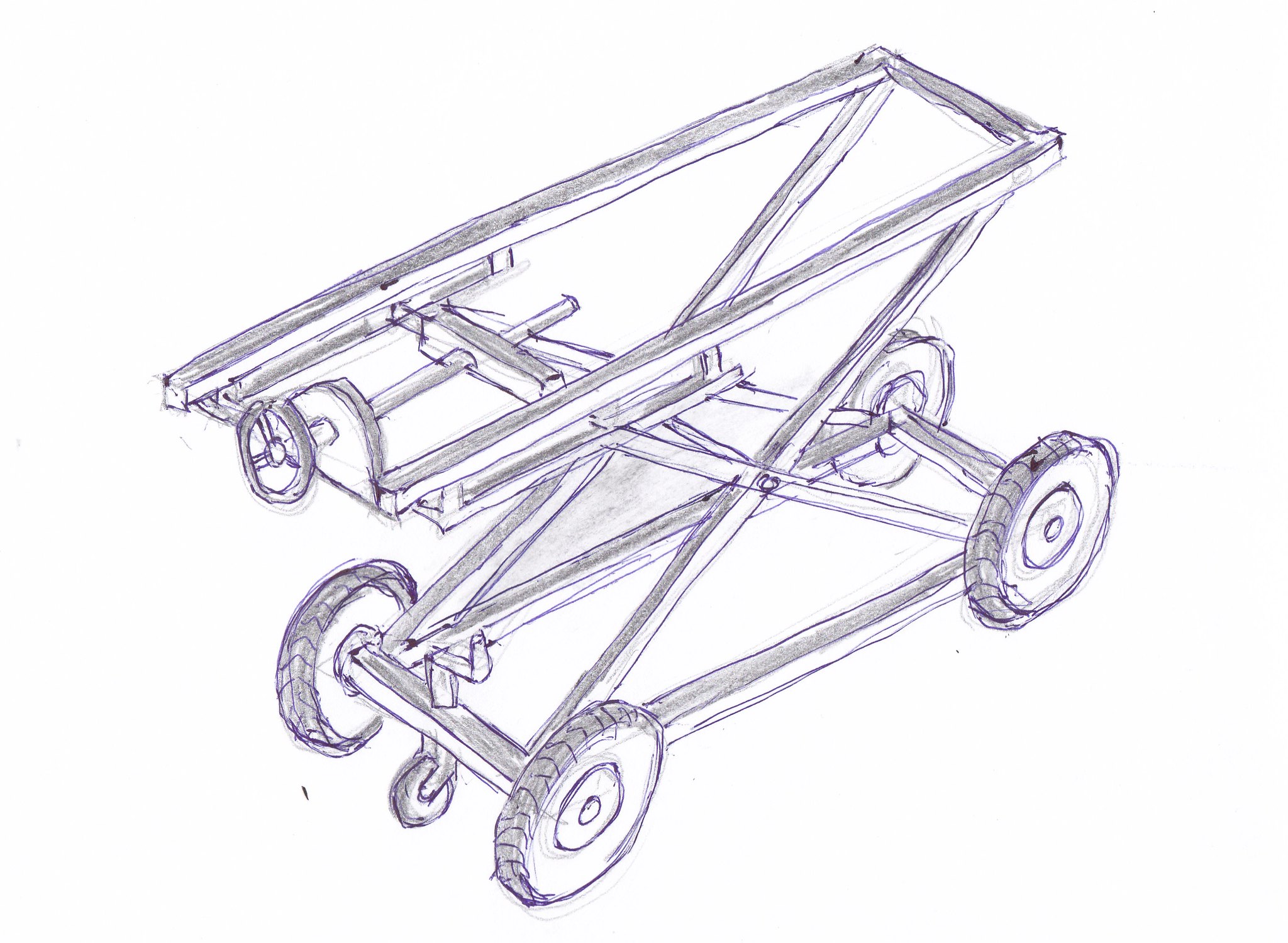 trolley sketch trolley sketch by Brian Leach, on Flickr |
|
oldnorton
Statesman
5" gauge LMS enthusiast
Posts: 692
|
Post by oldnorton on Jan 14, 2019 9:25:14 GMT
Hi Brian I made almost exactly the same design of trolley from 2" box steel. It works well and I will just add the following for you to consider in the design: 1. I have a hex head for the lift screw and that can accept a speed brace for quick drops or a ratchet lever for tough lifts. The hand wheel will limit leverage. 2. On mine the screw thread will bind when the ramp is in its lowest position because the leverage forces are just too great. It will have a lower limit of 2-3 feet which should be OK for the car boot. I have considered adding a gas spring but it would need one of around 100kg. 3. The design will wobble sideways a lot due to the flex of the bars and a big mass on top, so it is more secure to transport the loco in the down position. I put my wheels further out to add stability. The big pneumatic wheels are a good idea. Every success making it! Norm  |
|
|
|
Post by Roger on Jan 14, 2019 10:50:32 GMT
Well here's a rough and ready sketch of the trolley that I intend to make in preparation for handling the locomotive. It is a copy of David's with modifications suggested by Eddie and Lisa and with the large wheels recommended by Steve which by necessity have to be on a fixed axle, but so that maneuverability is achieved to make right angled turns in the shed I have added a jockey wheel that can be raised and lowered on a screw adjustment. To get the trolley up the step will require aluminium ramps as recommended by Roger. Brian trolley sketch by Brian Leach, on Flickr Hi Brian, That looks like a good solution. Might I suggest that the handle be of a Crank type rather than a round one with a handle sticking out? A crank type could be turned to a position where it didn't get in the way. I've been thinking about that step and imagining that you could probably lift one end up easily enough, since it's half the weight. With that in mind, perhaps another pair of wheels between the the ones at the end would allow you to lift up one end and pull it along to the middle wheels, then tip it so it's level again to get the back wheels on? They could be slightly clear of the ground so they didn't get in the way when moving it normally. If you don't think you can lift the front end, I suppose you could use the fact that you can wind the table up and down to assist you. Maybe adding some small wheels that stick out the front of the top section could be used. I'm picturing pushing the trolley up to the step so that the top wheels rest on the top of the step. Then you wind the table down so that the bottom wheels come up to a level where you can push the front on. Then it's back to plan A to get the back wheels up. Another idea which is a hybrid of the first two, is to attach two temporary wheels to the bottom of the bars that form the scissor lift. The idea is that you move the trolley to the step then wind up the table enough to fit the wheels, Then you drop the table which moves the middle wheels down below the level of the others, causing the table to pivot on those middle wheels. When the front wheels are high enough, you can roll the trolley onto the step, then raise the table enough to be able to roll the middle wheels onto the step, before raising it again so you can push the back wheels on. It might take a bit of modelling to find out how that might work out in practice, the middle wheels might need to have an extra lever to make them move enough for that to work without raising the table too high. Could be a complete non-starter, but it's interesting to think about. All good fun, and it keeps the brain alive! |
|
|
|
Post by jon38r80 on Jan 14, 2019 12:38:08 GMT
Instead of a bar or wheel handle for raising and lowering, a hex head on the end of the lift/lower screw and an electric drill and socket to drive up and down might be man enough and safe some puff. If the battery is flat on the drill a mechanics ratchet handle and socket would substitute for the drill and have a reasonable lever arm to make it easy to operate. You probably have most of those bits already.
|
|
jem
Elder Statesman
Posts: 1,064
|
Post by jem on Jan 14, 2019 18:04:21 GMT
I made an hydraulic scissor lift which will lift 350 KG ( it lifts my ride on mower) it lifts from 11 cms up to 120 cms the first 20 cms of lift is a real grunt, 2500 psi on the gauge, but after that it drops right down to 500 psi. if you are interested, I can let you have more information.
Jem
|
|
|
|
Post by runner42 on Jan 14, 2019 21:50:54 GMT
I made an hydraulic scissor lift which will lift 350 KG ( it lifts my ride on mower) it lifts from 11 cms up to 120 cms the first 20 cms of lift is a real grunt, 2500 psi on the gauge, but after that it drops right down to 500 psi. if you are interested, I can let you have more information. Jem Hi Jem, thanks for the offer and I am pleased to receive more information, it is still evolving so the more ideas I get the better. Brian |
|


