mpenn
Active Member

Posts: 11
|
Post by mpenn on Jan 26, 2019 17:58:38 GMT
I have made a start building Don Youngs Black 5 tender and would like to check if the part that I have squared in red is made from one piece. What is confusing me a little is the parts that I have lined in blue are these showing end on pieces? Not having used plans like these before they are taking a little to get used to understanding. Any advice would be much appreciated . Regards Mark . 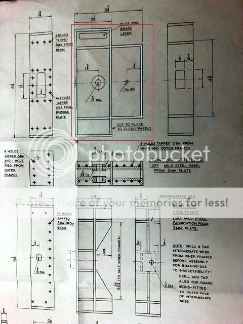 |
|
|
|
Post by RGR 60130 on Jan 26, 2019 18:52:40 GMT
The drawing isn't particularly good The view below your red box is the cross section on that centre line that passes through the 5/16" hole. You might like to consider a laser cut kit of parts to make life easier. Model Engineers Laser have lots of parts kits available here www.modelengineerslaser.co.uk/locoparts.aspx?loconum=21&locotype=3Reg |
|
stevep
Elder Statesman

Posts: 1,070
|
Post by stevep on Jan 26, 2019 18:58:45 GMT
Mark,
On the right-hand side, it says 'MILD STEEL FABN' - i.e. it is fabricated for several pieces of mild steel, welded, silver soldered or brazed together.
As Reg says, if you buy the pieces from Model Engineers Laser, they will probably be tabbed, so they fit together like a jigsaw, ready for soldering.
|
|
mpenn
Active Member
Posts: 11
|
Post by mpenn on Jan 26, 2019 19:12:25 GMT
Hi Reg
Thanks for the link, I will have a look at Laser cut parts .
Also didn't realise that bit of the drawing was the cross section knowing that does help a bit more.
Mark
|
|
mpenn
Active Member
Posts: 11
|
Post by mpenn on Jan 26, 2019 20:15:01 GMT
Mark, On the right-hand side, it says 'MILD STEEL FABN' - i.e. it is fabricated for several pieces of mild steel, welded, silver soldered or brazed together. As Reg says, if you buy the pieces from Model Engineers Laser, they will probably be tabbed, so they fit together like a jigsaw, ready for soldering. Hi stevep I have already cut some of the parts out but having looked at Model Engineers Laser I think I will get the parts from there . Regards Mark |
|
Neale
Part of the e-furniture
 5" Black 5 just started
Posts: 278 
|
Post by Neale on Jan 27, 2019 10:33:56 GMT
I'm at a similar stage although I have now made the front drag box and am working on the rear. I redrew the tender in Fusion 360 partly to help visualise exactly this kind of structure. I'm OK at reading engineering drawings but a zoomable/pannable/rotatable 3D view is much better to show how all the bits go together! Here are a couple of F360 screen shots showing an exploded view and a "finished" view. I chose to machine the individual components myself using CNC but I guess that the MEL laser-cut parts will look similar. Tab-and-slot helps hold the bits together while fixing; I welded the front drag box (looks very untidy but is strong) but I am planning to silver-solder the rear drag box as I have modified my cutting technique so that the parts fit better. 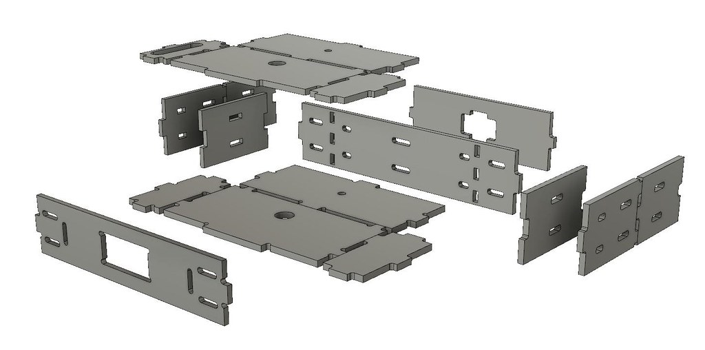 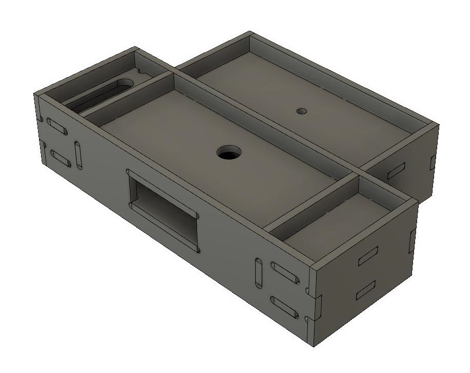 The bosses for the drag link pin are missing from this although I have fitted them on the finished item! I expect that you have seen a note on the drawing about cutting a clearance slot when assembling? This screen shot from F360 shows why - this is how things would look if built exactly to drawing.  |
|
mpenn
Active Member
Posts: 11
|
Post by mpenn on Jan 27, 2019 12:22:17 GMT
I'm at a similar stage although I have now made the front drag box and am working on the rear. I redrew the tender in Fusion 360 partly to help visualise exactly this kind of structure. I'm OK at reading engineering drawings but a zoomable/pannable/rotatable 3D view is much better to show how all the bits go together! Here are a couple of F360 screen shots showing an exploded view and a "finished" view. I chose to machine the individual components myself using CNC but I guess that the MEL laser-cut parts will look similar. Tab-and-slot helps hold the bits together while fixing; I welded the front drag box (looks very untidy but is strong) but I am planning to silver-solder the rear drag box as I have modified my cutting technique so that the parts fit better. The bosses for the drag link pin are missing from this although I have fitted them on the finished item! I expect that you have seen a note on the drawing about cutting a clearance slot when assembling? This screen shot from F360 shows why - this is how things would look if built exactly to drawing. Hi Neale Thank you for the Pictures they are just what I needed and do explain what I had confusion with. Yes I have seen the notes on the plans about a cut-out for the wheels to fit in and again it nice to see were the issue is . This has given me a boost to have a go at the ones on the plans. Although the tabs design does look better for assembly. Regards Mark |
|
Neale
Part of the e-furniture
5" Black 5 just started
Posts: 278
|
Post by Neale on Jan 27, 2019 12:49:25 GMT
I kicked around a few ideas for these drag box fabrications. One option is as DY describes in his articles, which sounds to me to be only just this side of impossible to achieve - rectangles of steel drilled and tapped into the edges to hold together with temporary bolts while silver-soldering. And the horizontal pieces are supposed to be wedged in place. Recipe for disaster? Another alternative is to use castings - Blackgates sell these as part of the Galatea tender design - another variation on the Stanier 4000gal tender. I would have gone laser-cut, but have managed to get my CNC router to cut for me which also gives me practice at developing the technique for a lot of other fabrications that this loco is going to need. I have started on frame stays using a similar approach. Pictures to follow!
|
|
mpenn
Active Member
Posts: 11
|
Post by mpenn on Jan 27, 2019 13:21:00 GMT
I kicked around a few ideas for these drag box fabrications. One option is as DY describes in his articles, which sounds to me to be only just this side of impossible to achieve - rectangles of steel drilled and tapped into the edges to hold together with temporary bolts while silver-soldering. And the horizontal pieces are supposed to be wedged in place. Recipe for disaster? Another alternative is to use castings - Blackgates sell these as part of the Galatea tender design - another variation on the Stanier 4000gal tender. I would have gone laser-cut, but have managed to get my CNC router to cut for me which also gives me practice at developing the technique for a lot of other fabrications that this loco is going to need. I have started on frame stays using a similar approach. Pictures to follow! Hi Neale In Hindsight I think you are correct about following don young's plans just been to look at the parts I have already made and come to the same conclusion you have . So I think the best option for me is to get the front and back box from Model engineers laser. I'm looking forward to seeing the frame stays. Regards Mark |
|
Neale
Part of the e-furniture
5" Black 5 just started
Posts: 278
|
Post by Neale on Jan 27, 2019 13:54:52 GMT
Lower frame stays. Tab and slot along the edges to locate the pieces. This was going to be difficult to clamp, so you can see the small spots of MIG weld at key points to hold everything together for silver-soldering. The weld is on the outside and where it can be easily filed off. Worked well. 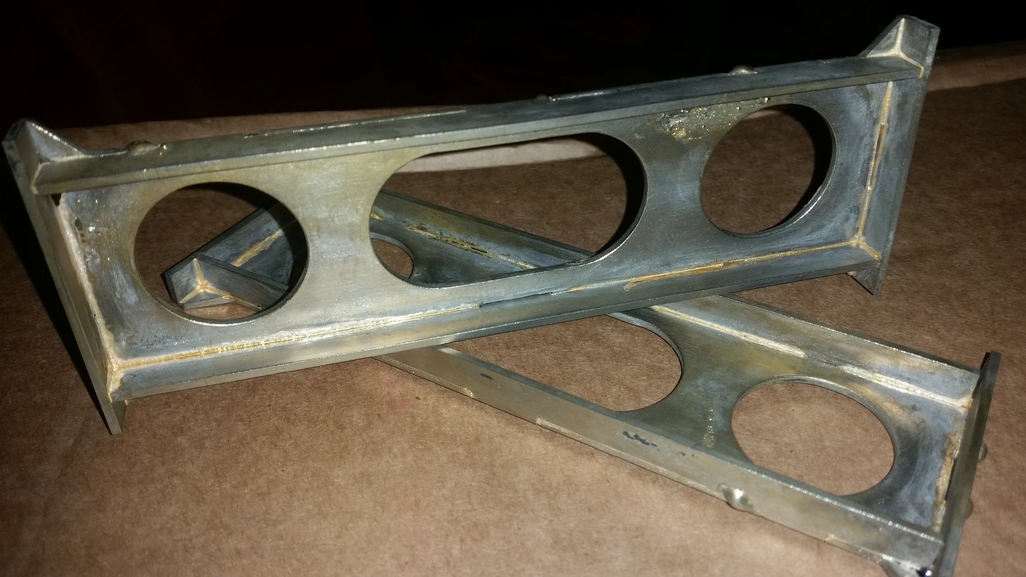 |
|
mpenn
Active Member
Posts: 11
|
Post by mpenn on Jan 27, 2019 14:19:26 GMT
Hi Neale
They are very nice the plans call out for 1.6mm steel folded over in the vice but I think the way you have done it is probably a lot easier.
Is that 2mm steel you have used ?
Mark
|
|
Neale
Part of the e-furniture
5" Black 5 just started
Posts: 278
|
Post by Neale on Jan 27, 2019 15:15:45 GMT
I'll try to remember to measure it next time I'm in the garage! I thought about folding, but I'm not sure that I could have made neat enough folds. I was looking at a part-built (the best way to look at a model!) BR 4MT at the Alexandra Palace show last weekend and the fabricated parts on that had very neat folds but I don't know how you manage to do that. Given access to CNC machining, though, I can get much more accurate pieces straight off the machine. Depends on what you have available and how skilled you are in using it! Personally, I don't like to rely on handwork when I can get a machine to do it for me. These frame stays (all of them) are also available from Malcolm at MEL, so it shouldn't be too difficult to reproduce what I have done - and probably a bit better as well! However, I have to say that I was quite pleased with the silver-soldering on these stays, which has come out pretty well. This is roughly where I am at the moment. Wheels, axles, and axleboxes, plus horns, are also machined. Once I have the frames, drag boxes, and stays all sorted, I can start riveting bits on. 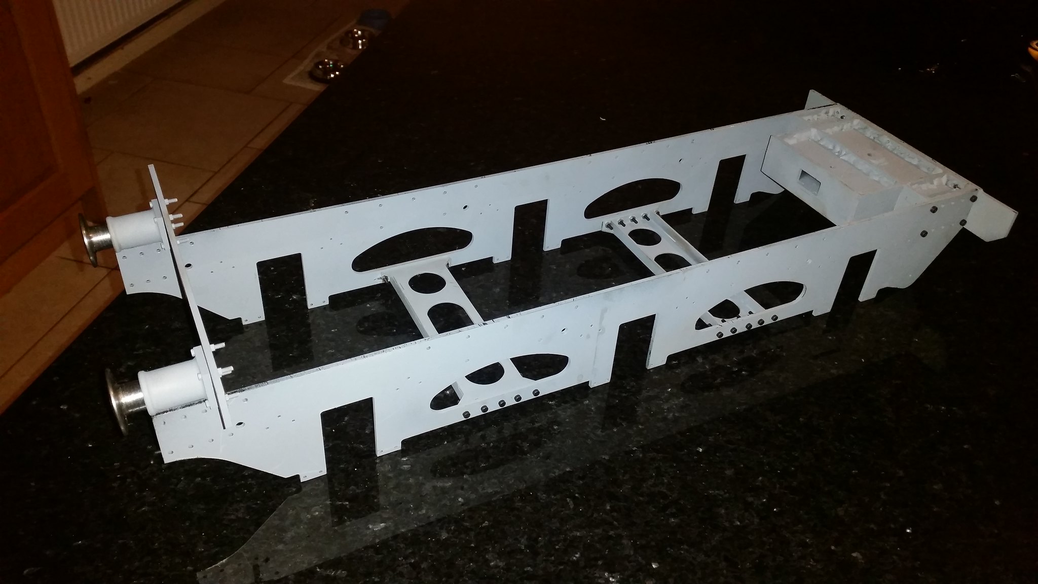 |
|
mpenn
Active Member
Posts: 11
|
Post by mpenn on Jan 27, 2019 16:33:45 GMT
That's looking good I have been looking at the parts available from MEL and don't think I will try bending the stretchers instead will use laser cut ones.
I will post pictures of the progress and the laser cut parts as soon as I get them.
Mark
|
|
Neale
Part of the e-furniture
5" Black 5 just started
Posts: 278
|
Post by Neale on Feb 20, 2019 22:25:27 GMT
Hi Neale They are very nice the plans call out for 1.6mm steel folded over in the vice but I think the way you have done it is probably a lot easier. Is that 2mm steel you have used ? Mark Sorry for delay - completely slipped my mind. I think I used 1.88mm steel (0.074"). At least, that's what it says on my Fusion 360 drawing and I'm sure that I would have measured the stock material for that. Sounds like an odd size, but it was a piece I picked up somewhere that seemed about right. Been a bit delayed recently but have now cut and tack-welded the rear drag box and it's pickled and waiting for silver-soldering. Next day or two with a bit of luck. |
|
mpenn
Active Member
Posts: 11
|
Post by mpenn on Feb 21, 2019 20:16:13 GMT
Hi Neale I have received the parts from MEL they are excellent the drag box took round 15 minutes to cut and file the parts and put together no soldering yet . Also ordered some other parts for the tender at the same time including the frame stretchers . 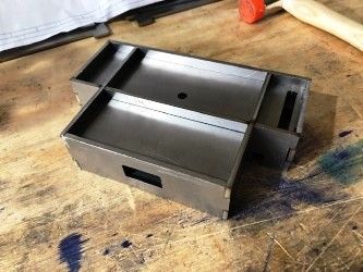 Drag box Drag box
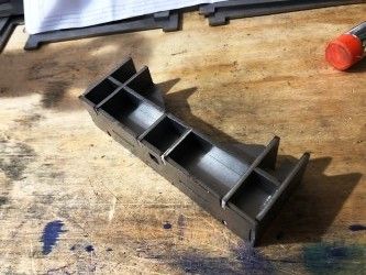 Rear box stretcher 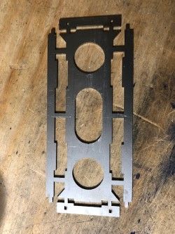 Frame stretcher 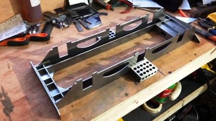 This is how far l have got . Mark |
|
|
|
Post by Deleted on Feb 21, 2019 21:04:27 GMT
Nice work Mark...you can't go wrong with Malcolm's products. Actually I was only just talking to him earlier today...  Pete |
|
mpenn
Active Member
Posts: 11
|
Post by mpenn on Feb 21, 2019 21:12:39 GMT
Nice work Mark...you can't go wrong with Malcolm's products. Actually I was only just talking to him earlier today... Pete Hi Pete Thanks and yes his parts are very good I will be wanting some more later  Mark |
|
Neale
Part of the e-furniture
5" Black 5 just started
Posts: 278
|
Post by Neale on Feb 22, 2019 10:22:01 GMT
It was only through sheer cussedness and a desire to do as much of the job myself that I could that led me to CNC-cut my own components. MEL kits would have saved me a lot of time for not that much more cost, in the overall scheme of things. And laser-cutting gives better detail than even my smallest 2mm cutter.
I silver-soldered my rear drag box last night; it's now in the pickle bath trying to get the scale off. Good luck when you start that process!
|
|
|
|
Post by Roger on Feb 22, 2019 12:49:28 GMT
It was only through sheer cussedness and a desire to do as much of the job myself that I could that led me to CNC-cut my own components. MEL kits would have saved me a lot of time for not that much more cost, in the overall scheme of things. And laser-cutting gives better detail than even my smallest 2mm cutter. I silver-soldered my rear drag box last night; it's now in the pickle bath trying to get the scale off. Good luck when you start that process! Why not use smaller cutters to get into the corners? With CNC you can easily go down to 1mm and I've even used a 0.5mm one on occasion. That's with the clumsy big spindle on my mill, so something higher speed would make it easier. Obviously you don't want to machine whole parts with something really small, but you can always drill the corners first and then clean up just those areas. 'Sheer cussedness' is an undervalued character trait in my opinion. |
|
Neale
Part of the e-furniture
5" Black 5 just started
Posts: 278
|
Post by Neale on Feb 22, 2019 14:59:33 GMT
As ever, there's a bit of history to what I was doing. I don't actually have a CNC mill; it's a CNC router which I built originally for woodworking. However, it is mainly built of welded steel with decent ballscrews and linear profile rails, and I wondered if it would be up to the job of cutting steel, using small cutters to suit the high-speed spindle (nominally 6K-24K RPM). After an experiment or two with cutters I had lying around, I bought some carbide cutters (2/3/4mm) designed for high-speed use with no coolant. I wasn't sure how well the 2mm cutters would stand up to this use but they've actually turned out to be much tougher than I expected. I do use the technique of roughing out with the larger cutters (usually the 4mm as it gives best cutting speeds) and then swapping to the 2mm to take out the corners, as far as possible. Your comments and my experience to date make me realise that I had forgotten that I could go down to 1mm in the same range of cutters. That would allow me to do tab-and-slot in the thinner steels for things like frame stays. I use Fusion 360 for CAD and CAM purposes and the CAM module is very good at generating tool paths for a smaller cutter to remove material that a larger roughing cutter left behind.
|
|


 Drag box


