Neale
Part of the e-furniture
 5" Black 5 just started
Posts: 278 
|
Post by Neale on Apr 16, 2019 13:46:26 GMT
Roger has made a number of significant points, including the fact that one of the key things is to identify the relatively small number of icons and tools that you need, and ignore the rest! I have run a few F360 tutorials for fellow club members, including online via video-conferencing, and one thing that stands out in my mind is that it is almost certainly easier to learn 3D CAD modelling if you do not come from a 2D CAD background! This sounds counter-intuitive, but it is because 2D CAD combines design and engineering drawing into one operation. 3D CAD separates these. I have had one "student" who tried to dimension his 3D model using 2D CAD techniques - always dimension from a single datum, that kind of thing. His model almost literally fell apart when we went on to look at how to modify what we had already done. In 3D CAD (where the D is Design, not Drawing) you are building a model that expresses your "design intent". Apart from a few key values, actual dimensions aren't that important at this point. One of my mantras is to never put a dimension in your model if you have another way to define something. What do I mean? Here is a simplified vice model that I have been using for teaching.  Something like this would take me, maybe, an hour or so to throw together. I can generate drawings of individual components that I can print and take into the workshop with a few mouse clicks in a minute or two. You could probably put the 2D drawings together in a 2D CAD package in a similar time. However, my model expresses my "design intent" in a number of areas. For example, the fixing holes for the fixed jaw are lined up to be central in the metal between the central recess and the bottom of the hold-down groove on the side. No dimensions used to position these holes - I actually tell F360 that I want them "in the middle" using various simple tools. So what? Well, maybe I look at the model on screen and decide that it's too narrow. I want a vice that's 75mm wide, not 50mm. Here is a second attempt. 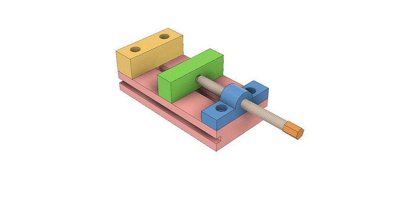 To get to the second model from the first took me the time it takes to open a menu, change "50mm" to "75mm", and click OK. Job done. Literally, that was all that was needed because my model incorporated my "design intent", not dimensions apart from a very few - which I could change. New manufacturing drawings? Into the drawing module, open the drawing I want, click "update drawing", reprint. Job done. F360 does everything except go the workshop and tear up the old version of the drawing (I think that that's in a future release...). And those hole positions will be dimensioned from a single datum, because that is what I need when I'm standing in front of the milling machine, even though my design intent was expressed differently. It's a different mindset, and I know that it doesn't suit everyone. However, I'm building a Don Young-design Black 5 at present, and everything is being redrawn in F360 as I go. Easy to see DY's big error in the tender this way.  So much easier to see what's going on, and converts to conventional drawings or direct to toolpaths for CNC cutting (for example, for all those fabricated frame components) at the click of a mouse button. Well, more-or-less! See how the wheel flange overlaps the front frame stay? Bet DY wouldn't have made that mistake if he'd been using F360!  I used to use TurboCAD, and the thing that really sold me on F360 was that I could go back and change things so easily - edges stay lined up, hole positions still line up between components with no effort. With TurboCAD, I generally ended up deleting the drawing and starting again. If nothing else, that is a big win for me. And I still have a stack of scrap paper for the odd quick one-off! |
|
|
|
Post by Roger on Apr 16, 2019 14:02:44 GMT
Hi Neale,
All very good points. It does take a while to get used to the idea of creating constrained models, I'm still improving the way I do this.
For the uninitiated, there's a palette of tools that allow you to force certain conditions, say that a line must be horizontal or perhaps perpendicular to another. You can also force a group of features, say holes, to all have the same diameter. That means you can change one, and they all change. You can also make lines co-linear, or Using construction lines and tying holes to one means you can move the line and they all move together. When you're designing things, these tools are invaluable. In all, there are 14 of these constraints you can apply at the sketch level.
Once you've created 3 dimensional features, you can then duplicate, mirror or revolve copies of these, so there's a second level of control you have over these elements. Beyond that, once you have completed models, you can again constrain separate parts in similar ways so that you can force surfaces to mate or edges to hinge.
You can also name key dimensions to create parametric models. I have a parametric model of face and radial sealed 'O' rings. I can change the cross section, the inside diameter and the amount of compression and save the new model as a specific 'O' ring for a job. I have a similar one for creating two hole flanges of the type you often need for valve glands and such like. I have parametric models for Nuts, bolts and Cap screws too which saves drawing each size.
I appreciate that this might be baffling to a newcomer, but you'll find that you can adopt these features gradually as you develop your understanding.
Hopefully this makes it clearer as to why 3D CAD is so useful.
|
|
|
|
Post by Donald G on Apr 16, 2019 17:41:15 GMT
Hi Roger
I did watch 3 videos about starting to draw in Fusion, these were not ones I had looked at before, but, this one actually started to make a little sense to me. Unfortunately I am out tonight, but I do intend to continue tomorrow evening when I am in and hopefully , given time, I will crack the basics and produce a 3D image of some part.
Thanks again
|
|
|
|
Post by 3405jimmy on Jul 12, 2019 18:21:24 GMT
As an alternative to the soon to be dead Draftsite, I have been playing with Solid edge 2D. its my kind of price , free. Anyone else dipped their toe in the SE pool ? If so have you worked out how to change the background colour to anything but white ? "It's doin my ed in"  |
|
uuu
Elder Statesman
 your message here...
Posts: 2,807
|
Post by uuu on Jul 12, 2019 19:14:03 GMT
I use it, and like it - but I've not tried changing the background. One thing I've not figured out is how to change the coordinate origin, so I have to do that once I've transferred to CamBam (which is not free, but good value). In theory the 3D version is also free for students and hobbyists, Siemens website but I've not tried it. Wilf |
|
|
|
Post by cplmickey on Jul 12, 2019 21:09:09 GMT
I've changed to nanoCAD which is free and similar in some ways to Draftsight. Not used it a great deal yet but seems ok so far. Ian
|
|
|
|
Post by David on Jul 12, 2019 22:21:25 GMT
I downloaded Q-CAD - www.qcad.org/en/ - to look at an old DXF and I think it would be good enough for what most of us do. It's free. |
|
Geoff
Hi-poster

Posts: 169
|
Post by Geoff on Jul 13, 2019 3:01:27 GMT
I've been trying to learn Fusion 360 over the last couple of months with varied success. My main purpose is for patternmaking on my 3D printer. Once I got my head around a few basics and became familiar with parametric modelling, a light went on. I drew my dome in 3D and when one of our club members needed a dome for his pug, it took me 10 minutes to resize it and add a chucking piece. It took 2 hours to print (while I watched the footy) and it was cast the following week.
The constraints in Fusion 360 are the thing I have the most difficulty in understanding, but the more I use it the better I get. Back to the tutorials I think!
|
|
|
|
Post by Roger on Jul 13, 2019 6:00:52 GMT
I've been trying to learn Fusion 360 over the last couple of months with varied success. My main purpose is for patternmaking on my 3D printer. Once I got my head around a few basics and became familiar with parametric modelling, a light went on. I drew my dome in 3D and when one of our club members needed a dome for his pug, it took me 10 minutes to resize it and add a chucking piece. It took 2 hours to print (while I watched the footy) and it was cast the following week. The constraints in Fusion 360 are the thing I have the most difficulty in understanding, but the more I use it the better I get. Back to the tutorials I think! Constraints as definitely the way to go when 3D modelling, regardless of the package you're using. It's counter intuitive though in my opinion because you're often better off drawing lines or circles away from their intended size and destination and then to set them to be at tangents, coincident, concentric etc to whatever you already have. On Alibre, the colour of the lines change to show when they are fully defined. Constraints always constrain two things, and sometimes you can unwittingly attempt to over constrain something by the way you go about it. It won't let you do that though. Another thing that's extremely useful is to project lines from other parts of the model while retaining their relationship to them. So for instance you can define one 'O' ring groove diameter on a shaft, then make the next one further along follow the first. In Alibre, once you've created a useful object, say a nut or flange, you can name the key dimensions and save it as a parametric model. I just copy my parametric model of a Cap Screw for example, save it where I want to use it, and then change the diameter and length. Some of the details are related to each other, for example the depth of the head is the same as the diameter of the screw. My 'O' rings are defined like that too so I can specify an ID, the cross section and the amount of compression and it draws the whole thing complete with the flats. I'm sure the time spent on tutorials is well spent. |
|
|
|
Post by 92220 on Jul 13, 2019 8:26:21 GMT
When I was a contract design draughtsman, back in the early 1990s, I used to draw in Autocad 13 3D almost exclusively. When I retired I bought Autocad 2004 and used the 3D solid modelling. It was exactly the same as the Autocad 13 3D but with added features which WAS how Autocad worked. This made it very easy to use an updated version. Not any more!!! Unfortunately my 2004 died on me and getting it back up and running through Autocad was a minefield, so I replaced it with the AutocadLT which doesn't have 3D. It was very good for it's age, and I had an 'add-on' that allowed motion. One thing you could do with the 3D model was to place it into 'Paper space' and that gave you 2D views which were dimensioned in the normal 2D way, and printed out . I've tried using Fusion 360 just can't get my head around it, having worked extensively in the old Autocad 13 3D. It's a totally different system and not so intuitive......so I'm sticking with 2D.
Bob
|
|
|
|
Post by 92220 on Jul 13, 2019 8:33:45 GMT
I mentioned that I use the 3D solid modelling. The latest 3D programs that I have seen, don't seem to use solid modelling. Why is that.? It is so easy to produce 3D models. You have all the usual geometric shapes, like cubes, pyramids, cylinders etc. that can be produced to any desired size. If you want a hole in across the diameter of a cylinder, you just add a smaller cylinder on thge desired centre line and instruct it to 'subtract'. You end up with a cylinder with a hole. When drawing, you just think like a machinist. You can subtract and add to make any shape you like. Dead easy so i don't understand why they have gone away from this. If you want a fancy shape, you just draw it as a 2D shape and then extrude it to make it into a solid. Then use it like any of the standard solids. If that was still available maybe I'd be drawing in 3D but I'll have to stick with my 2D.
Bob.
|
|
|
|
Post by simplyloco on Jul 13, 2019 12:19:48 GMT
I mentioned that I use the 3D solid modelling. The latest 3D programs that I have seen, don't seem to use solid modelling. Why is that.? It is so easy to produce 3D models. You have all the usual geometric shapes, like cubes, pyramids, cylinders etc. that can be produced to any desired size. If you want a hole in across the diameter of a cylinder, you just add a smaller cylinder on thge desired centre line and instruct it to 'subtract'. You end up with a cylinder with a hole. When drawing, you just think like a machinist. You can subtract and add to make any shape you like. Dead easy so i don't understand why they have gone away from this. If you want a fancy shape, you just draw it as a 2D shape and then extrude it to make it into a solid. Then use it like any of the standard solids. If that was still available maybe I'd be drawing in 3D but I'll have to stick with my 2D. Bob. With Fusion 360 you can either select a cylinder or extrude one as you suggest. And its free! John |
|
|
|
Post by Roger on Jul 13, 2019 13:57:22 GMT
I mentioned that I use the 3D solid modelling. The latest 3D programs that I have seen, don't seem to use solid modelling. Why is that.? It is so easy to produce 3D models. You have all the usual geometric shapes, like cubes, pyramids, cylinders etc. that can be produced to any desired size. If you want a hole in across the diameter of a cylinder, you just add a smaller cylinder on thge desired centre line and instruct it to 'subtract'. You end up with a cylinder with a hole. When drawing, you just think like a machinist. You can subtract and add to make any shape you like. Dead easy so i don't understand why they have gone away from this. If you want a fancy shape, you just draw it as a 2D shape and then extrude it to make it into a solid. Then use it like any of the standard solids. If that was still available maybe I'd be drawing in 3D but I'll have to stick with my 2D. Bob. Hi Bob, you've just described Fusion360 as far as I've seen. That's how Alibre works too. I think the problem is that you're trying to make Fusion 360 work like Autocad and it's a completely different animal when it comes to the user interface. I'd started using Imagineer which was very intuitive, just like Alibre when my brother in law had just finished a two week course on AutoCAD. When he tried to show me what it could do, he couldn't remember enough to do anything useful. I showed him what imagined was like, even though I hadn't done much with it. They were chalk and cheese. I thought AutoCAD was ghastly, loads of command line drawing commands and such like where you had to remember the syntax. I understand that later versions attempted to use the mouse to generate more of these, but it was basically nailed onto the old software. This was a dead end, and why they threw it away and started from scratch. You can get used to anything, however bad it is, but it's probably better in the long run to bin the old software and learn the modern way of 3D modelling since it's pretty universal across all of the packages you can get now. |
|
uuu
Elder Statesman
your message here...
Posts: 2,807
|
Post by uuu on Jul 13, 2019 15:33:05 GMT
... I have been playing with Solid edge 2D. ...have you worked out how to change the background colour to anything but white ? ... I think I've found it. At least for my copy of ST7. Click the button in the top left corner, to bring up the list of choices including open, save etc. At the bottom is a rectangular button "Solid Edge Options". In the resulting dialog box, choose "Colors" from the left hand list, and then change the setting of the "Sheet" choice. You can choose a standard colour, or the "More" button at the bottom brings a full-choice palette. When you've chosen, click "Apply", then "OK". Wilf |
|
kipford
Statesman
Building a Don Young 5" Gauge Aspinall Class 27
Posts: 566
|
Post by kipford on Jul 13, 2019 16:32:32 GMT
Bob
Most 3D CAD systems use Solid Modelling where primitives, extruded shapes, thickened surfaces etc by addition and subtraction are used to create the Model. Certainly Fusion 360, Alibre, Creol, Solid Edge, AutoCAD Inventer, Solid Works, Siemens NX, CATIA all work that way, hence why it is possible without too much hassle to convert from one system to another. At work experience with CATIA was desirable for new employees, but not essential as a weeks training would normally have them up and running. Some freebees such and Rhino use surfaces only.
Regards
Dave
|
|
|
|
Post by 92220 on Jul 13, 2019 17:29:21 GMT
Hi Roger.
With the Autocad 13 and 2004, syntax never came into play. Everything was mouse picked from screen menus as standard. However, It was possible to make up a lot of special commands that could be accessed by the mouse. When I was a contract design draughtsman, I used my own equipment, and Autocad, and I used a tablet and pointer, and made up a hard-copy menu that I fixed to the surface of the tablet. The entire surface was just like a touch-screen monitor. All I had to do was touch the relevant command box with the pointer and the command was initiated. Just about every command I ever needed was on that tablet and it could be worked about twice as fast as using the screen menus. It also had lots of extra commands that I had written in Lisp, which unfortunately, AutocadLT won't recognise. I still think solid modelling is far easier than surface modelling as the way shapes are made up is so logical. I did try Fusion 360 but couldn't get anywhere with it, having used all the standard Autocad versions as they came out, from Acad10 up to Acad2004 I think my brain is on strike............probably an 'age thing'!!! I must admit it would be nice to do my drawings in 3D, but I'd rather spend time building the loco than learning a new program.
Bob.
|
|
|
|
Post by 92220 on Jul 13, 2019 17:40:52 GMT
Hi Dave.
When I tried Fusion 360, it didn't seem like a solid modelling program. Maybe the old system is so ingrained in my brain I just can't get my head around the new system. Perhaps I will give it another try, but maybe the sensible option is to try and get Autocad to give me a new installation code so that I can re-install my Acad2004, which I did a lot of 3D work with, in the old days. At least I'd only have to refresh my memory rather than learn a new system.
Bob.
|
|
|
|
Post by Roger on Jul 13, 2019 18:51:07 GMT
Hi Dave. When I tried Fusion 360, it didn't seem like a solid modelling program. Maybe the old system is so ingrained in my brain I just can't get my head around the new system. Perhaps I will give it another try, but maybe the sensible option is to try and get Autocad to give me a new installation code so that I can re-install my Acad2004, which I did a lot of 3D work with, in the old days. At least I'd only have to refresh my memory rather than learn a new system. Bob. I think it's a lot easier than you imagine. Just follow some YouTube videos step by step and forget how you always do it at the moment. It won't take long to get the hang of it. |
|
|
|
Post by David on Jul 14, 2019 3:03:55 GMT
F360 will allow you to build up the bodies using 3D solids and join/cut operations, chamfers, etc with no 2D sketches required. Although I can't imagine getting through any sort of real object or programming it without using some sketches. This may be a bias built in to F360.
Most videos I've watched start with a 2D sketch with a ton of constraints, extrude it, and then start with the 3D changes. Maybe that's where the confusion is if you're used to starting with solids.
Because I had no prior experience with 3D CAD I went with the majority and start with a 2D sketch, usually with the most complicated profile of the part on it.
|
|
|
|
Post by 92220 on Jul 14, 2019 7:51:53 GMT
Hi Roger and David.
I'll take your advice and give it another go. Thanks.
Bob.
|
|