|
|
Post by John Baguley on Mar 23, 2019 21:01:45 GMT
Hi all,
Has anyone any experience of how the valve liners are fitted on the 5" Winson Britannia? I see that there is a grubscrew at either end of the bore in the cylinder to secure them. I've undone those but the liner doesn't want to budge. Are they glued as well?
Having rebuilt the valve gear on the one that I'm supposed to be getting running on air I find that although the LH cylinder runs perfectly, the RH one has a very bad blow straight up the exhaust. I'm pretty sure that it's not the valve as I've made new PTFE heads for the bobbins and they are a good push fit in the valve liner bores. I'm rapidly reaching the conclusion that the valve liner is not sealing into the cylinder block and I think I'm going to have to bite the bullet and remove the liner.
I seem to recall that the Winson Black Fives had O ring seals on the outside of the liners as the builder had to fit the liners themselves. Are the Brits the same? If so, the O rings could have been damaged when the liners were fitted. Are they one piece liners or made in two halves? It's difficult to tell just by looking at them. I know that the Winson Brit is based on the Spink/Perrier drawings where the liners are in two halves and pressed in but there is no guarantee that Winson made the valve liners as per the drawings.
Any information would be gratefully received before I start attacking the cylinder block with the blowlamp!
John
|
|
|
|
Post by Jock McFarlane on Mar 23, 2019 21:41:14 GMT
On the 7 & 1/4" version the liners are in 2 parts divided at the steam inlet. The liners are a fairly slack fit so plenty of Loctite 638 might do the trick of sealing them. The grubscrews seem to be pointless.
You can locate the 2 halves by shoving a piece of round bar down the steam inlet and butting each half against that.
Regards
JM |
|
|
|
Post by Jim on Mar 23, 2019 21:59:10 GMT
I made the valve liners for Boadicea in three parts and they are gentle press fit into the valve body. It could be that rather than being glued in the valve liner was pressed in. It might be worth testing to see if that is the case. I would suspect the 'O' rings and grub screws were used because the liners were a not a good fit and so free to move in the valve body.
Just a thought.
Jim
|
|
|
|
Post by flyingfox on Mar 24, 2019 8:09:43 GMT
Greetings John.
On the Winson produced kits for the 71/4 Britannias, the cylinder blocks were drilled halfway, from each side, then a reamer put through in the vain hope this would make the bores line up. The two piece liner was then locktited in place with 638, supplied with the kit. Much of this locktite was squeezed out as the liner went in and most of them leaked between the liner & the block.
The liners will come out OK if the block is given a good period of heating, at about the max temperature a domestic oven can manage.
I understand that the same method was used for the 5 in version, but there were more batches of kits produced in 5 in, and manufacturing methods did change somewhat.
There is also a problem where the liner blocks the port, and needs opening up. Also the pistons on some models were too short, and allowed a lot of steam to waste.
They can be made to work well if you persevere!
Regards
Brian
|
|
|
|
Post by Cro on Mar 24, 2019 8:48:23 GMT
John,
I can only reiterate what has been said above, the winson 9f was in two halves and yes most the leaking was around the liners.
I now have two new two piece liners which were machined to a much closer push fit and then we loctited them in for good measure. I also opened up the valve ports and squared the holes off and it's much improved from what it was before. Next job is to make new bobbins to slightly closer fit most likely with PTFE rings.
Adam
|
|
|
|
Post by John Baguley on Mar 24, 2019 19:15:23 GMT
Thanks for the replies chaps 
So it seems that the liners will be Loctited in. The cylinder block is cooking nicely in the oven at 250°C as I write this. Hopefully this will loosen the liners and I'll take it from there.
John
|
|
|
|
Post by John Baguley on Mar 24, 2019 20:37:22 GMT
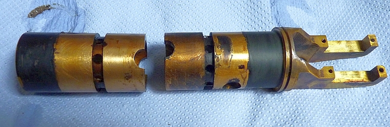
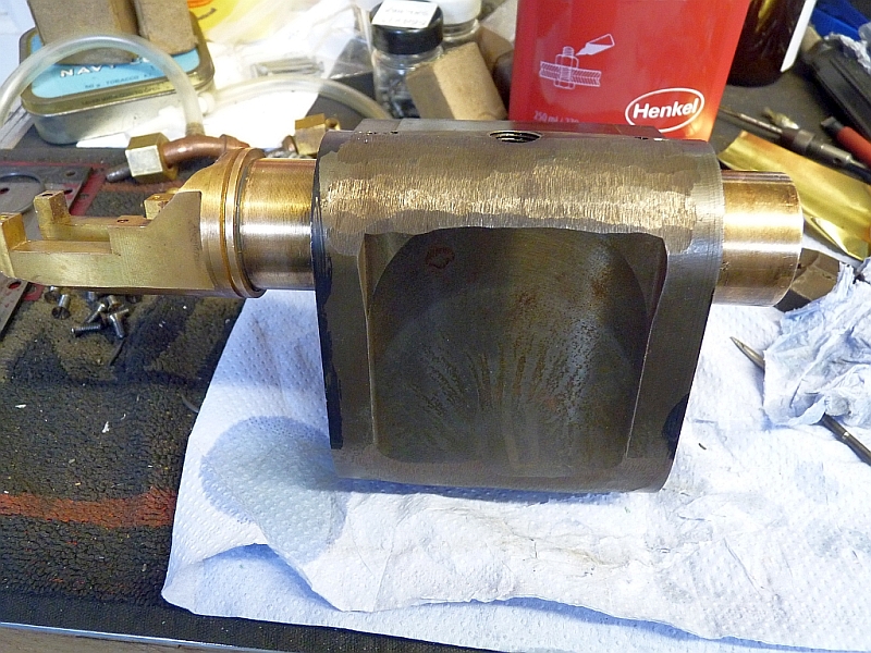
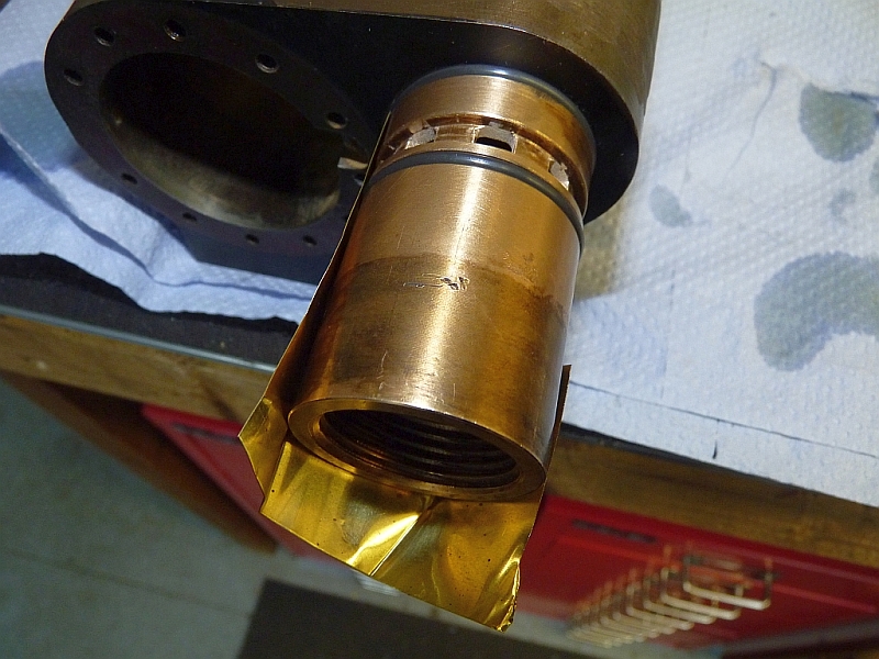
Well, that was easy enough. The liners came out easily once heated.
There doesn't seem much evidence of sealant so it's no wonder that they leak.
I'll give everything a good clean up and see what sort of a fit the liners are in the cylinder. If not too bad I'll machine grooves in the outside of the liner and fit Viton O rings. The buggers won't leak then!
John
|
|
|
|
Post by Jock McFarlane on Mar 25, 2019 9:28:02 GMT
Well, that was easy enough. The liners came out easily once heated.
There doesn't seem much evidence of sealant so it's no wonder that they leak.
I'll give everything a good clean up and see what sort of a fit the liners are in the cylinder. If not too bad I'll machine grooves in the outside of the liner and fit Viton O rings. The buggers won't leak then!
John
Are you going to take your own advice and make those holes in the annulars into square ones ?
JM
|
|
barlowworks
Statesman
 Now finished my other projects, Britannia here I come
Posts: 874 
|
Post by barlowworks on Mar 25, 2019 12:46:12 GMT
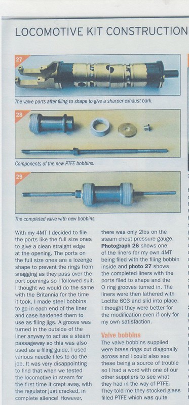
Doug Hewson, in his series on fettling the Modelworks Brit advises to file up the liner holes as below. May give it more of a bark.
Mike
|
|
|
|
Post by John Baguley on Mar 25, 2019 15:46:20 GMT
I'd forgotten all about the Doug Hewson series in ME. That would have helped a lot!
I'm not sure how far to go with this actually. The loco belongs to someone else who just asked me if I could get the chassis to run so that they can put it all back together and then sell it. I may alter the ports etc. just for my own satisfaction. At least then whoever buys it will get a decent running loco.
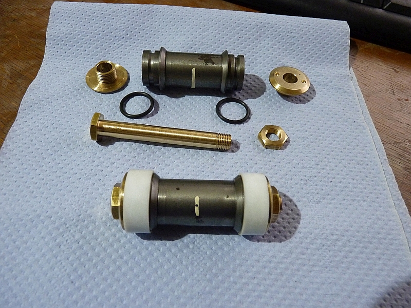
The valve bobbins did come fitted with what looks like the Doug Hewson PTFE heads but they were in a pretty poor state with rounded edges that would have made accurate valve timing impossible so they had to be replaced.
One mod I have done is to get rid of the tedious method of adjusting the valve using lock nuts either side and replaced that with a threaded sleeve that the bobbin floats on. Now it's easy to adjust the valve from the front end of the cylinder by screwing the sleeve up and down the valve rod with a box spanner.
John
|
|
|
|
Post by John Baguley on Apr 2, 2019 21:12:14 GMT
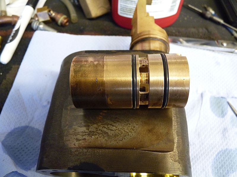
Well, I've sorted the leaking valve liner out. I did modify the ports as suggested and milled them square. I then machined two O ring grooves in the liners either side of the ports and fitted 1.78mm section Viton O rings. Well, I intended to fit 1.78mm rings but had a Mr Bozo moment when machining the grooves and made the rings too loose a fit! Fortunately, I had also bought some 2mm section rings and those saved the day.
Before refitting the liners I enlarged the steam passages from the ports to the cylinder ends. These were originally just a 3.5mm drilled hole but I managed to enlarge them to 4mm x 8mm which has trebled the area.
Refitting the liners was fun and I initially destroyed two O rings trying. The O rings caught on the edges of the exhaust outlets in the cylinder block which cut the O ring. Rounding off the edges helped a little but not enough to avoid damaging the rings. I think this was the problem encountered by the Black Five builders. I then hit on the idea of using a strip of 3 thou brass shimstock to fit inbetween the liner and the bore, positioned so it covered the exhaust ports. As the liners were a pretty loose fit in the cylinder block (there was a 8 thou gap!) it was possible to press the liner in and then pull the shimstock out again. No damage to the O rings this time.
I didn't use Loctite 638 as I doubt that I would have been able to get the liner in and pull the shimstock out before it went off. Instead, I used Loctite 290 which is a high strength wicking type threadlock put on after the liners were in place. The 290 is so thin that it just gets sucked into the gaps around the liner and makes a very strong bond. The liners are going nowhere!
I did fit the two grubscrews again but had to move them outwards a bit as the original positions were slap bang in line with one of the O ring grooves and I didn't want to risk damaging the ring by screwing down onto it.
I refitted the cylinder this afternoon and ran the chassis on air and the cylinder was perfect with no leaks from the liner or the valve. The chassis now runs very nicely on 20psi of air with no continuous blow from the blast pipe!
All I've got to do now is repeat the process with the other cylinder. It should go a bit quicker this time as I now know what I'm doing (?) and I've got all the set ups worked out to machine everything.
John
|
|
|
|
Post by cplmickey on May 28, 2019 20:09:18 GMT
Inspired by John I have returned to my Winson 9F with the intention of doing similar things with the valves (they have the same cylinders and hence the same issues as the Brit ones do). Only one of the grub screws came out so a session of spark eroding was called for to remove the other.
My liners proved to be much more difficult to remove. After a couple of heatings in the oven I still couldn't budge them. So I put them in the freezer for a couple of days, the thinking being that the bronze liners would shrink more than the cast iron lump so breaking any remaining loctite bonds and being reduced enough to tap out. And so it proved - I've just removed them both in less than 5 minutes.
At the Society workshop some cylinders have already had the steam passages enlarged by spark eroding so the tip already exists as does the jig to hold them at the correct angle, so that will be the next task although I can't get over to do that until at least next Wednesday.
|
|