|
|
Post by terrier060 on May 6, 2019 22:40:24 GMT
Thanks Steve for the thread tip, and Dave I would like those tender drawings yes please. Does anyone have any good backhead pictures of Princess Elizabeth. Mine have not come out very well. I need to know where the drain cock lever is in the cab among other things. Here is the valve unit - just needs the pipework soldering to it. The drawing on the previous page does not show correctly the live steam inlet. This is on the bottom fitting in the position shown with two very small pipes connecting it to the central hole (which is blanked off). The port face is easy to get at to polish it if necessary. The steam oil should make the flat valve seal pretty well. It is raised with a groove between it and the inner body of the base unit as per the drawing, which cannot be easily seen under the flash lighting.  Drain cock multi-valve Drain cock multi-valve by ed cloutman, on Flickr |
|
|
|
Post by terrier060 on May 7, 2019 15:17:46 GMT
I had a chat on the phone with Roger this morning which brought me out in a bit of a cold sweat! I had been meaning for some time to check the valve events as I had the sudden horrible feeling that I had got the inside cranks set incorrectly. So I spent several hours putting the cylinders on again which means removing the coupling rods. All very fiddly. As it happens all is well as long as Jackson has got it right because I have set the cranks the same as him. I don't know where I got the eight beats from - must have been dreaming. Sounds a good idea though but would require four sets of valve gear! Here are the approximate valve events. It is a long time since I designed a valve gear but I think it looks about right. I do not, however want to get into a long discussion on valve gears so if there is any inclination to do so please be kind enough to start a new thread. My main concern is to get the loco running on compressed air. The drawings show the valve events on the right-hand cylinder in full forward gear. The LHS is just put there as a comparison at the right-hand positions. The positions are as follows for the RHS: 1. The slide valve has just reached the fully open position at about 26 degrees before the piston has reached the half-way position on the forward stroke. 2. The slide valve has just closed at about 26 degrees after the piston has reached the half-way position on the forward stroke. 3. The side valve is just at the point of opening at about 5 degrees before the piston reaches the end of travel on the forward stroke. 4. The slide valve has just reached the fully open position about 26 degrees before the piston has reached the half-way position on the return stroke. 5. The slide valve has just closed at about 26 degrees after the piston half-way position on the return stroke. 6. The side valve is just at the point of opening at about 5 degrees before the piston reaches the end of travel on the return stroke. The cranks are set as per Jackson: 1. When the outside LH crank on the centre wheel is forward, the inside LH crank on front driving wheels is backwards. 2. The outside crank on the RH centre wheel is vertically down while the inside RH crank on the front driving wheels is vertically up. It all sound double-dutch to me, and the drawings look confusing as well, even though I drew them!!  Crank settings and port openings Crank settings and port openings by ed cloutman, on Flickr |
|
|
|
Post by terrier060 on May 8, 2019 14:58:14 GMT
|
|
|
|
Post by terrier060 on May 9, 2019 0:14:09 GMT
|
|
Midland
Elder Statesman

Posts: 1,870
|
Post by Midland on May 9, 2019 8:00:03 GMT
That cab roof is useful as I have to make a new one for mine. Thanks Ed.
D
|
|
Midland
Elder Statesman
Posts: 1,870
|
Post by Midland on May 16, 2019 8:15:03 GMT
Hi Ed
Been looking at tenders. I have the works drawings for the straight sided one in the loco profile and can copy these. It really is a standard Fowler tender made slightly longer to take the increase from 3,500 gallons to 4,000 gallons of the H2O. The wheel base is a couple of feet longer. There great resiistance to anytghing bigger on the LMS as it would have meant longer turntables, a big expense where a few more troughs were cheaper.
I fear there is quite a lont of work piled up before tender construction.
Cheers David
|
|
|
|
Post by terrier060 on May 16, 2019 9:07:25 GMT
Yes David - I agree. I have had the cylinders off and fitted 'O' rings in the glands. I am now waiting for the Hylomar to arrive and some brass from Western Steam for the inner steam chest cover (lost the original somewhere - will probably turn up some day) - both of which should arrive today. Then assemble the cylinders and see how the chassis runs on compressed air.
I agree - tender some way off.
|
|
|
|
Post by terrier060 on Jul 5, 2019 17:24:08 GMT
Hi all Been away for a bit , but have at last got the chassis running. It's a bit stiff at the moment - needs a bit of running in, but it is amazing the power in four cylinders. The increase in speed is when I notched her up. 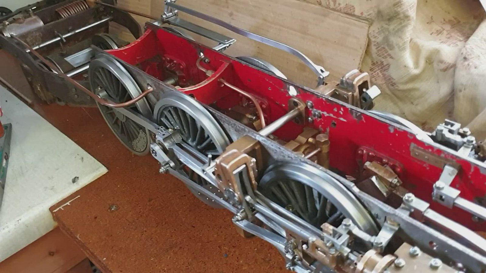 Princess Princess by ed cloutman, on Flickr |
|
|
|
Post by Deleted on Jul 5, 2019 19:05:17 GMT
That runs lovely Ed....well done sir...
Pete
|
|
|
|
Post by terrier060 on Jul 6, 2019 21:13:58 GMT
Thanks Pete. I have run it for about an hour and it is freeing up.
Ed
|
|
Midland
Elder Statesman
Posts: 1,870
|
Post by Midland on Jul 8, 2019 9:01:57 GMT
Yes David - I agree. I have had the cylinders off and fitted 'O' rings in the glands. I am now waiting for the Hylomar to arrive and some brass from Western Steam for the inner steam chest cover (lost the original somewhere - will probably turn up some day) - both of which should arrive today. Then assemble the cylinders and see how the chassis runs on compressed air. I agree - tender some way off. Ed If you are planning to come to the Fosse, I will bring the tender drawings for both the PR and the similar Fowler locos. D |
|
|
|
Post by delaplume on Jul 8, 2019 9:12:25 GMT
Hello everyone------- would the Fowler tender behind 2968 at the SVR be of any use to copy / measure / photo etc ??
|
|
|
|
Post by terrier060 on Jul 9, 2019 8:32:02 GMT
Hi Dave - thanks for that. I won't be at Fosse, but will try and get down to Southampton at some point. Will contact you in advance.
That's a good idea Alan - they must be very similar I would have thought.
|
|
|
|
Post by delaplume on Jul 9, 2019 9:00:00 GMT
During my earlier days at the SVR I had a 3.5" gauge Princess Marina 2-6-0 .....Working in the machine shop at Bridgnorth I'd make contact with many different owners/repairers etc and amongst them I met "Big Colin" ( Never did know his full name !!) ...the team leader on the 2968 restoration programme ......I'm fairly certain he said that the Fowler tender was initially fitted to these locos by Crewe because there was a shortage of "Modern" tenders at that time in stock..........A rolling programme was to have seen the whole class retro-fitted with the same one as a Black 5 but in the case of some --- 2968 included --- this never happened..
One thing I do remember quite clearly is how narrow that Fowler tender was compared to the Stanier-designed cab having fired it a few times later on...
Alan
|
|
|
|
Post by terrier060 on Sept 5, 2019 10:27:26 GMT
Silverfox see the bottom of my page one which I think will make the connection of the pumps clear. The eccentrics are 180 degrees out of phase.
Ed
|
|


