|
|
Post by doubletop on Jan 18, 2022 8:02:58 GMT
I’ve moved on to the bunker now. I know you’ll be asking yourself “What is he doing, he hasn’t finished the running, plates, the tanks or the cab roof and now he’s started the bunker”. It was always my intention to sort of do a proof of concept before spending ages on each sub assembly to find something that trips me up down stream. By that I mean prove that every major sub assembly fits together on a Martin Evans Dart. You’ll recall I had a bit of wobbler when it came to fitting the cab front to the boiler. The other factor being I can’t progress with the bunkers because I’m waiting for the parts from Polly, which are still stuck in China, as part of their ticky tour to New Zealand. Now I’ve got the roof completed to this point.  The next thing to get to fit was the interface between the back of the roof and the bunker, and that started to be fun… The drawings show a number of angle pieces that are required, each has a series of holes defined in tables. For the first I checked the hole spacing and drilled the series of holes, that then didn’t match the supplied platework. What was wrong? The middle pair of holes had a different spacing to the rest. That required a remake, no short cuts, just follow the table. Next was the angle on each side of the bunker holding it to the floor. I find there are no dimensions on any of the drawings (57 & 58) defining the inset from the outer edge of the angles. In fact the lack of these dimensions were beginning to concern me as the fore and aft and lateral location of the bunker could not be confirmed. There are no dimensions to confirm the location of the predrilled base plate, so no obvious datum. I started with the holes for table K. After a lot of searching I determined the correct inset value is 0.2343”. However, I start by doing the other face, diligently following Table S, (the offset is easily determined from the supplied side plate). I offer the result up to the plate and the holes don’t line up. Polly have used some dimensions other than those in the table..... At this point I go through the other drilling tables relating to the bunker (Tables K, L, N, O, P, Q, S and T) and begin to wonder which are correct and which aren’t. This is going to need an email to Matthew at Polly to confirm what is what. The reply from Polly could take a little time to get the answer so I consign the work back to the draw where I keep all the parts from the Polly kit. “What is this at the back of the draw?” I ask myself, finding Parts 18, 19 and 25. All the floor angles, that require folding, the “T” and “L” sections that require silver soldering and all the other joint plates. I knew I had the “T” and “L” sections but had completely forgotten about the other bits.  Progress can now be made, and probably pretty rapidly, if riveting can be described as rapid. Pete (a much happier chappie than he was earlier today) |
|
|
|
Post by doubletop on Jan 21, 2022 8:36:36 GMT
Now I’ve established that I don’t need to make any angles straps or joining plates for the bunker it is time to make a start. First up is the cab rear, for no other reason that it doesn’t involve any radiused corners or rolling. Something that has been a concern since the kit arrived. However, the roof went OK so maybe the two rear bunker plates will go OK as well. If you take a look at the bunker parts the 3 plates in the top of this photo show the left and right sections and the tunnel for the brake standard. Each has laser cut fold lines The left and right plates the bunker shelf and the angle to join to the cab sides. The tunnel has 4 folds to form the three sides and the angles to join it to the left and right sections.  This went pretty well but the tunnel needed a bit of heat to help coaxing it to the correct shape.  One thing that I hadn’t understood was the purpose of the extra tab with two holes. Then when investigating the cab seats I realised that those two holes were part of the mounting for the left hand seat. That made it convenient to make a plate with holes to the dimension of the seat mounting and it would ensure the correct width of the overall cab rear when riveting it all up. Cunning foresight on Polly’s part  The riveting was straight forward. All the rivets along the top and down the left and right hand side are dummies. Well real rivets, but not fixing anything. The rest join the three sections together and secure the cosmetic ¼” angle on the lower front edge.  When I did the slide outs in the roof they did seem a bit tight so for the coal hole door I sandwiched some 10thou shim between the rail and the cab back. I hope that will be sufficient. You will notice some scrapes and dings in the job and some witness lines where the Formit had done the folds. I think I said I wasn’t too concerned about that and time to try out my present from Santa.  A few minutes zap in the sand blaster and problem dealt with.  As far as I am concerned this is a must with brass work, it creates an ideal key for the etch primer. In other projects I’ve found that any paint damage is only to the top coat, the etch primer isn’t affected so the topcoat is easily repaired. That done I felt I little more confident in tackling the lower rear panel. That was another job for th D&L attachment, however it needed a second pressure bar making. The roof radii are 7/16” inside the panel but the bunker is 7/16” outside the panel. As the kit uses 1.2mm brass (0.047”) then the diameter of the pressure bar needs to be 0.781”. I happened to have some 20mm bar which is 0.787” result!!. No photo of the folding process I’m afraid but much the same as before. Two lines 0.781” apart either side of the fold centre line to allow allgnment with the pressure bar using square.  Eureka!! Perfectly square and exactly 12.0625” to the outside of the two return faces. On a roll (OK pun intended) why not try the upper panel. I believe in Karma in these circumstances, if it is going well keep going, if it isn’t just stop because it is only going to get worse. Tea sometime helps.  I was concerned that the location of the rear roller would prevent the full curve from being created, reversing the job (turning it 180deg) in the rollers solved this however care needs to be taken not to roll the vertical section of the panel. Just put the job into the rollers from the back and stop when the fold line gets to the rear roller.  It is rolled close to the final radii but I need make the “L” and “T” sections, on the left of this picture before I can finalise the forming the curve. Gary already has a “How To” on this in his Paddington build. Paddington PlateworkGetting this far I had to rivet up the forward side panels and see how it all went together. As you will recall that was the purpose of doing the bunker now without the tanks or roof completed.  It is coming along and much faster than I anticipated. The pre drilled components, especially all the bunker parts, certainly speeds up the build. Still a long way to go though. Pete |
|
|
|
Post by doubletop on Jan 26, 2022 7:28:44 GMT
Having formed all the parts once I got going on the riveting it came together fairly quickly. The longest task being trimming the rivets to length, But the shear helps considerably.  The last thing to be fitted was the lower angles and novice error I didn’t do a check fit before starting the riveting. Everything else had been going so well what could possibly go wrong?  I hadn't folded the angles, supplied in the kit, correctly and resulted in the bunker sitting about 25thou too high. There was nothing for it but to remove the 40 odd rivets holding them on and make new ones from stock brass angle, the same that had been used for all the other corners. I was a little apprehensive as the Polly supplied parts weren’t drilled to the John Smith drawings so didn't have the dimensions and I’d been caught out before. However, diligent measuring and checking of the supplied parts and I had a table to hole positions I was happy with. As the existing angles weren’t going to be reused the pan heads on the inside of the job were ground off with a Dremel. The angle prised off and then the rivets pulled from the outside with a pair of snips used for fine electrical work. Some to a bit of persuading by pressing them from the back but eventually they all were removed. Dentistry came to mind. The new angles were made and fitted and everything assembled. The test was mounting the bunker on the base. All the holes lined up perfectly. Testament to the other rolling and folding. I am not riveting my bunker to the base I am using 8ba countersunk screws so the base can be removed for maintenance. Particularly for access to the cross tank that will be installed for the injector feed. Now it all fits together nicely   Next up are the bunker corners, again following Gary’s example. Mine will be in copper as supplied in the kit. Pete |
|
Gary L
Elder Statesman

Posts: 1,208
|
Post by Gary L on Jan 26, 2022 16:23:19 GMT
That looks really beautiful Pete! And all the really critical work is now done. Great stuff!
Gary
|
|
|
|
Post by doubletop on Jan 26, 2022 19:32:22 GMT
That looks really beautiful Pete! And all the really critical work is now done. Great stuff! Gary Gary Thank you. It is coming together and very satisfying when all the parts go together as expected and the sub-assemblies’ line up without the need for any major tweaking to get alignment. There is still plenty to do. As I said next is the bunker corners, but as they are in copper they can take any amount of beating into submission. As well as the supplied parts a contingency I have found that I do have a small sheet of 1.2mm copper. So less stress to get it right. That said, whenever I know I have a plan B plan A goes better than expected. The troubles tend to occur when there is only a plan A. After that I’ll go back to the cab roof and finish the parts that fit to the roof to the bunker. That is why I did the bunker before I finished the roof. Better to know your destination before setting off. I’m still waiting for the parts, from Polly, that are apparently stuck in China. In the meantime, I have already started the conversation with Polly on what we are going to do if they don’t arrive soon. Pete |
|
|
|
Post by doubletop on Jan 28, 2022 8:45:14 GMT
I've not been doing much today. I have progresed on the formers for the bunker corners but wll save that for later. I'm pretty much copying what Gary did for his. I have been tinkering with my CAD model for the platwork, adding the bunker. I decided I didn't need to do every plate, so just did a shell that could be used for placing other parts. I realised that I had previuosly started work on a full Dart model in CAD so thought I'd overlay the platework model onto it.  Incomplete but it gives you a flavour of the progress. Pete |
|
|
|
Post by doubletop on Jan 28, 2022 23:46:56 GMT
I’ve made the formers and squared off the curved section as Julian had advised Roger and Gary. There is really nothing new here at all. I basically copied what Gary did.   I did use bolts to secure the fences as that way I could locate them more accurately than using wood screws. I need to do ensure the fences are reasonably accurate as some of the holes in the plates have already been drilled.  Now I’m stalled in making a decision. Do I cut the plates at the fold point, like Gary did, or do I just go for it and hope the copper complies? Gary was using brass which would have been harder to form. The supplied copper part does have a peculiar shape, is there any reason for this? Can the experts see what that shape is for? I did consider calling Matt at Polly but I did call him two days ago about something else so don’t want to get to the stage of seeming too needy. Any suggestions please? Pete |
|
Gary L
Elder Statesman
Posts: 1,208
|
Post by Gary L on Jan 29, 2022 2:38:21 GMT
Hi Pete
The risk with pre-drilling the holes is that the forming operation will try to drag the edges towards the bends. You might overcome this, copper being more malleable, if you can clamp the drilled edges down really firmly. You’ve nothing to lose anyway.
The funny shape is just to give you plenty of spare metal. You might want to trim it back a little as your shaping progresses, to avoid trying to stretch/shrink metal that won’t be needed.
I think you will form that corner most easily by cutting it and silver-soldering- it is a perfectly respectable technique, but getting the cuts in the right place is the trickiest part.
It’s only metal, and not enormous chunks, so if you make a mess, just cut some more and try again! It isn’t the end of the world.
Good luck
Gary
|
|
|
|
Post by doubletop on Jan 29, 2022 3:10:18 GMT
Hi Pete The risk with pre-drilling the holes is that the forming operation will try to drag the edges towards the bends. You might overcome this, copper being more malleable, if you can clamp the drilled edges down really firmly. You’ve nothing to lose anyway. The funny shape is just to give you plenty of spare metal. You might want to trim it back a little as your shaping progresses, to avoid trying to stretch/shrink metal that won’t be needed. I think you will form that corner most easily by cutting it and silver-soldering- it is a perfectly respectable technique, but getting the cuts in the right place is the trickiest part. It’s only metal, and not enormous chunks, so if you make a mess, just cut some more and try again! It isn’t the end of the world. Good luck Gary Gary I've just had another look at your thread and noted that the metal from the lower compound curve had overlapped the upper curve so had come to the same solution. 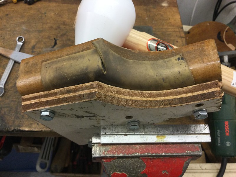 I'd came here to say I'd decided to do the cut and found your post. One of the reasons I had stalled, if making the cut is the way to go why didn't Polly do it when they laser cut the parts? BTW it may be 4:00pm here that makes it that you sent your post at 2:40am! That's service for you! regards Pete |
|
Gary L
Elder Statesman
Posts: 1,208
|
Post by Gary L on Jan 29, 2022 16:05:38 GMT
Hi Pete A late night, we live the high life in the UK!  Polly can’t cut the slit in advance, because they don’t know how/where your beating is going to stretch the material. It’s the same with that odd shaping you were querying yesterday. I was mildly disconcerted to find that my straight edges, those that would be drilled for the rivets, were no longer dead straight and square after the beating was done. The metal had distorted a little, despite the clamping ‘plate’. Fortunately I had just enough spare to true matters up afterwards*. I hope it works out for you, but I’ll take this belated opportunity to caution people that it is likely to be best to drill the rivet holes last. Good luck Gary *EDIT: No I didn't, I misremembered; I had to patch the edges and then true up afterwards.I think it is p5 of my Paddington Platework thread. -G |
|
|
|
Post by doubletop on Feb 1, 2022 8:21:07 GMT
Hi Pete A late night, we live the high life in the UK!  Polly can’t cut the slit in advance, because they don’t know how/where your beating is going to stretch the material. It’s the same with that odd shaping you were querying yesterday. I was mildly disconcerted to find that my straight edges, those that would be drilled for the rivets, were no longer dead straight and square after the beating was done. The metal had distorted a little, despite the clamping ‘plate’. Fortunately I had just enough spare to true matters up afterwards. I hope it works out for you, but I’ll take this belated opportunity to caution people that it is likely to be best to drill the rivet holes last. Good luck Gary I agree with you regarding don’t drill the holes first, but I’ll get to that a bit later.
I decided to go with cutting the slit and carefully measure the 1.875” line from the top where the bunker fold line occurs. The plates were annealed and the process started.
Not a good start, the first folds hit in the wrong place. Not to worry I’ve done enough copper bashing to know that these things are recoverable. A few more anneals later and time in the citric acid pickle and things were beginning to look the part.
Not pretty but getting there. The thing that needed sorting was the void at the fold point. Larger that the one Gary had to deal with. Two small pieces of 3mm copper did the job.
 Some work with the file tidied them up
 The next thing to deal with was the excess copper that needed to be removed. One way I’ve dealt with this I the past, doing boiler plates etc, is to mill the excess off. I used the former to hold the plates down. Careful manipulation of the X and Y on the mill table and the cutter offset slightly gets the job done.  With the excess removed I offered the plates up to the bunker and there was no way that they were the correct size. Way too big. I scratched my head wondering how that could be and realised, novice error I’d made the formers to the outside dimension of the bunker, from the drawings. I hadn’t allowed for the thickness of the copper. After a moment of “I need to start again" I realised that I could reuse the existing formers by moving the fences in by 1.2mm and recutting the large radius 2.25:+1.2mm (2.297”). Removing the 3mm copper inserts from the fold point I could reuse the existing copper. So, a repeat of the copper forming and two new 3mm inserts. A lot more fileing I was back to where I had thought I was the day before.  Back to Gary’s comment on not drilling before doing the forming. Not only does the material pull away from the fences but it stretches lengthways and none of the holes line up. The hole for the hand rail in the centre of the plate is now elliptical.
As for the cut, would it be possible to form the plates without it?
Pete |
|
Gary L
Elder Statesman
Posts: 1,208
|
Post by Gary L on Feb 2, 2022 1:42:11 GMT
Bad luck Pete, but the corner shaping is the important bit, and that looks pretty authentic to me. You could fill the holes with rivets and silver solder, or just cut them off and solder on a fresh strip of metal. As you say, when metal bashing most things are recoverable.
Gary
|
|
|
|
Post by doubletop on Feb 4, 2022 7:50:54 GMT
Bad luck Pete, but the corner shaping is the important bit, and that looks pretty authentic to me. You could fill the holes with rivets and silver solder, or just cut them off and solder on a fresh strip of metal. As you say, when metal bashing most things are recoverable. Gary It is only the line of holes in the formed plate that joins the front half of the bunker that is an issue. Filling the holes is certainly an option as they are only 1.2mm I'm not dealing with that at the moment as I'm not joining the two halves together just yet as I will be putting a cross tank in the lower part of the bunker for the injectors. My main tanks are dry and I carry 20litres of water in my riding wagons. Today I moved back to the cab roof and the rear supports. Unlike the John Smith design the Polly kit has a slide out roof.  Although I had made a second curved angle when I did the one for the spectacle plate the rear one needs to be split into three, left, centre and right hand sections. The centre is relatively easy to deal with but the left and right hand sections need to be soldered to the verticals to ensure they are stiff enough to support the roof without the slide out centre in place. I did ponder how I was going to ensure the joint the parts was correct but realised I had the cab rear plate that could be used as a template ( see the front spectacle plate for more details on the joint) That was all well and good to make the parts but how was I going to be able to hold them in the correct position while I soldered them together? Then another moment of inspiration, I had the check gauge I’d made for checking the roof fold.  Job done  Pete P.S. It's been 2 months so spoke to Polly last night about the order of parts that had gone on a tour of China. They are resending then to me today. If the others eventually arrive in return them to Polly. |
|
|
|
Post by doubletop on Feb 6, 2022 6:46:59 GMT
The next job was the fish plates that are part of securing the cab roof to the tanks and bunker. You will recall that the primary objective of this project is access of this project is accessibility and maintainability over authenticity. If you were to build this kit as drawn things would be riveted together or secured by a lot of “rivet bolts” or slotless screws making easy removal of the major assemblies hard, if not impossible. Look at the drawings the cab roof is held on by 17 x 10BA screws or bolts on each side (marked in red).    I set out with the intention of using the minimum number of screws replacing them with dummy rivets and using hex head bolts so they could easily be removed when required. First task was the six fish plates. Another case of “the dimensions are on the drawing somewhere” but after they had been established a simple machining job.  Again, the DRO smooth arc function used to put the curve in the rear plate that goes in the bunker.
A trail fit and all is well.  The next problem was how to drill the rivet holes in the tank and bunker plates what they are on the inside. For some reason the kit doesn’t come with them already drilled. It was getting late, maybe something will come to me overnight….. …… The next morning I’d barely sat down when the solution came to me. Bolt the fish plates onto the outside of roof and drill from there.
The rivets are to be flush to the outside of the cab, I still need to clean these up some more.  I had built the cab roof with the rear angle extending down to the rear shelf of the bunker. I did feel that over time this could be susceptible to damage and as I didn’t intend to use bolt in the lower section so maybe I should trim them off and permanently rivet the lower section in the bunker.  Which I’ve now done  Then came the surprising revelation. With the angles on the cab roof locating on the inner face of the tanks and bunker and the roof itself locating on the outer face of the fish plates the roof tends to clip in on its four corners by itself. Therefore, the decision has now been made that only 4 x 10BA hex bolts will be used on each side to secure the roof. The 4 bolts shown here and, apart from the 6 rivets holding the lower rear angle pieces in place, all the rest will be dummies.  So only 8 bolts in total holding the cab roof on, not the 34 that the drawings. So much easier to remove the cab roof when required. With each tank held on with 4 cap screws should make access relatively easy.to the inside motion for routine oiling etc.  Pete |
|
|
|
Post by doubletop on Feb 12, 2022 20:57:26 GMT
A bit of an update on what I’ve been up to. The replacement package of parts from Polly is on its way to me and I should see them early next week. In the meantime, I’ve been occupying myself with the small parts that need making at some point. Lifting Rings Tank Vents Tank Fillers Handrails Number Plates Steps Etc Once again, I followed Gary’s approach to the lifting rings. I’ve done my rings in stainless, only because that’s what I had available. I’ve never had any problems silver soldering stainless, I use the Harris black flux. With the lathe set to 8TPI, the 1/8” rod fed through a tool holder and turning the chuck by hand all very easy. Here it is after I’d cut off the excess.  I clamped stack in mill vice and carefully cut through with a slitting saw.  I was wondering if the stack would hold in place once each ring was cut through. I got my answer when I removed the saw blade. The stack just collapsed onto the table.  The only thing I did differently to Gary was parting the rings before machining the flat. I wasn’t too sure how well my parting tool would accept the intermittent cuts. Doing the flats one by one wasn’t too tedious.  As my tanks are going to be dry the tank vents were just going to be a simple machining job and solid, so no photos. Next was the tank fillers, the DRO smooth arc function again to produce the former.  The hand rails and number plates were recovered from my existing cab. I’d made them some years ago. (You will see from this why I’m replacing the platework.)  The parts had been made to the John Smith drawings so they fitted perfectly.  Next up is the other tank filler parts and then the steps. By then the bits from Polly should have arrived.
Pete
|
|
|
|
Post by doubletop on Feb 13, 2022 9:31:30 GMT
Ever since the drawings were published in ME in 2012 I’ve regularly gone back to the drawing for whistle shroud and something just doesn’t look right to me. I can’t seem to reconcile what the front view tells me with that of the side view.  Looking at the photos I can see what it should look like but I don’t think the drawings reflect what is really a simple piece of sheet metalwork.  The part that confuses me, in the drawings, is the lower portion of the ‘wings’ that, on the side view appear to protrudes ½” from the small vertical plate that fits to the whistle bracket. Whereas in the front view (and the photos) the front edge returns to the vertical plate. Is it me or is the drawing wrong? What am I missing? Pete |
|
|
|
Post by andyhigham on Feb 13, 2022 11:37:10 GMT
That drawing is appalling. Is it made in two pieces joined half way up? Screwed riveted or soft soldered together with no overlap. It looks a totally different shape to the photo
|
|
|
|
Post by doubletop on Feb 13, 2022 21:09:03 GMT
That drawing is appalling. Is it made in two pieces joined half way up? Screwed riveted or soft soldered together with no overlap. It looks a totally different shape to the photo I’m coming to the conclusion it is the drawing and not me. There is an instance of the shroud being made in two parts. The story goes that the smaller one was used but wasn’t adequate and a bit more was tacked on. However, I’ve gone through my selection of photos captured from the web and some have the join and some don’t appear to have it. I'll go for the simple option. I think it is clear that this is a folding job with the ‘wings’ folded in two steps. No fancy press work making an odd shape.  I’ll see what I can come up with in CAD Pete |
|
Gary L
Elder Statesman
Posts: 1,208
|
Post by Gary L on Feb 13, 2022 23:50:17 GMT
Hi Pete
The GWR fitted several shapes of whistle shield. Yours is about the tallest due to the height of the cab roof from the top of the firebox. Most of them shared the common feature of not being a straightforward trough (that would be too easy!) Note how the back of the shield has a short vertical piece at the bottom before the fold that angles the rest of it backwards, then there is often a further fold at the top to return it to vertical to take the supporting bolt that can be seen in many of the photos. As with most things, the ideal is to find a photo of your particular loco number (or match your loco number to your best photo(s)) and try to reproduce it in metal. To my eye, top row nos 3 & 4 and bottom row no 4 are the most ‘typical’ but you have plenty of variants to pick from!
HTH
Gary
|
|
|
|
Post by doubletop on Feb 14, 2022 8:42:12 GMT
Hi Pete The GWR fitted several shapes of whistle shield. Yours is about the tallest due to the height of the cab roof from the top of the firebox. Most of them shared the common feature of not being a straightforward trough (that would be too easy!) Note how the back of the shield has a short vertical piece at the bottom before the fold that angles the rest of it backwards, then there is often a further fold at the top to return it to vertical to take the supporting bolt that can be seen in many of the photos. As with most things, the ideal is to find a photo of your particular loco number (or match your loco number to your best photo(s)) and try to reproduce it in metal. To my eye, top row nos 3 & 4 and bottom row no 4 are the most ‘typical’ but you have plenty of variants to pick from! HTH Gary I'm doing 1466 and from the photos I believe that is the one with the split. On my various trips to Didcot I didnt get decent photo of the whistle shroud. In the meantime some success, and how wrong was I? I’ve spent a good part of the day coaxing Fusion 360 into producing something sensible but I now have something that should do the job. Mostly my inexperience and heading down blind alleys and having to back out and try something different. The various compound angles contrived to make the next function not work so another approach was required. You’ll notice the that the 15Deg ‘lean back’ actually needs a fold of 17.2 deg. I had to do them empirically until I got the truly vertical parts to sit vertically.  You will notice how similar this is to the original I posted yesterday. But now I have the flat pattern that I can use.  You will see that the lower mounting plate section isn’t included in the flat pattern. It would be impossible to include. I’ll just make it separately and silver solder it on. Pete |
|


