61962
Seasoned Member

Posts: 129 
|
Post by 61962 on Oct 22, 2016 11:21:19 GMT
Hi A possibility for the difference is that the two buffers were cast at different workshops from different patterns. There is a fair probability that the patterns although made from the same drawings could have “local” differences. These local differences were often as a result of the old pre grouping rivalries. Doncaster and Darlington even had slightly different shades of apple green because of this. The other thing is in this day and age we expect everything to be made exactly to a highly detailed drawing. In those days some things were left to the discretion of the craftsman and should a pattern be damaged it would not be out of the realms of possibility that it would be slightly changed as part of a repair. Regards Paul I think Paul's right on this. Looking through a couple of books on FS and the LNER pacifics the original patterns for the Spencer Moulton double cased buffer stocks had a greater convex radius than Pete has produced. The front buffers for the A4 had a convex radius of 1 5/16"and a concave of 3/4" and I would guess this was similar to the ones used on the A1, A3, O1 O2 early K3, V2 etc.. Don's drawing looks to be in accord with this and FS appears to have one original and one non standard, perhaps produced in BR days long after Spencer Moulton had disposed of the patterns, so perhaps Pete needs to rework the profile. The Haynes Manual for FS has some very good photographs, particularly the one showing a pacific hung up to find it's centre of gravity at the beginning of chapter 4. The works drawings reproduced in the same book also show this profile quite clearly. Unfortunately Pete has added the footsteps to his buffers. Sadly his lovely work will need to be undone since his 1939 loco didn't have them. I think they must have been added to FS during the 90's. I've seen photos recently from the early 90's when they were absent and 2004 when they were present. Sorry Pete. Julian, LNER used the Spence Moulton rubber springs in these double cased buffers and in draw gear. I remember visiting Shildon works in the 70's where there were piles of these composite steel and rubber washers for fitting to new and repaired wagons of exactly the same size as those fitted to the back of FS's front buffers. I think some modern wagons use a type of rubber spring in the draw gear. Eddie |
|
pault
Elder Statesman

Posts: 1,497
|
Post by pault on Oct 22, 2016 12:08:34 GMT
Looking at some of the pictures I have of 4472 taken at Carnforth in about 1982 there are no foot steps on the front buffers.
|
|
|
|
Post by Deleted on Oct 22, 2016 12:28:39 GMT
Hi Unfortunately Pete has added the footsteps to his buffers. Sadly his lovely work will need to be undone since his 1939 loco didn't have them. I think they must have been added to FS during the 90's. I've seen photos recently from the early 90's when they were absent and 2004 when they were present. Sorry Pete. Eddie Hi Eddie, I will have to concede to that one, no I hadn't noticed this, easy to rectify but a shame none the less, I kind of liked the steps.....lol I disagree about profile though, there are many pictures that support Don's drawing and perhaps yes it is as you say a difference in works patterns, the picture in the Haynes manual isn't FS so could be a different pattern although the quality isn't that good,being bleached out a little by the light, they certainly look sharper to me than today's buffer which has a more rounded look to the angled face. Here's 4472 at Wembley so I would guess that these are the original patterns..  same again in 1928  These 3 are after Pegler bought her..none look like the right-hand buffer as fitted today but notice how light causes an effect with a variation on how sharp they can look.    Cheers Pete |
|
davidk
Active Member

Posts: 32
|
Post by davidk on Oct 22, 2016 12:59:17 GMT
|
|
jma1009
Elder Statesman
Posts: 5,901
|
Post by jma1009 on Oct 22, 2016 21:39:36 GMT
Hi Pete,
I am sorry to have 'started a hare', though the excellent knowledgeable contributions have been of considerable interest. I dont know whether this is correct but my large tea mug that is in daily use is an M&S mug of FS and the buffer stocks are shown painted black!
Cheers,
Julian
|
|
pault
Elder Statesman
Posts: 1,497
|
Post by pault on Oct 22, 2016 22:04:43 GMT
I would say the 2003 picture has the steps fitted. In my 1982 picture the stocks are black although I'm not sure if that was an official LNER policy. A silly question what use are the steps? The only thing I can think of is to get onto another vehicle coupled in front. Having said that in this day and age I would have thought the lack of hand holds would have prohibited this.
|
|
pault
Elder Statesman
Posts: 1,497
|
Post by pault on Oct 22, 2016 23:50:48 GMT
1982 Carnforth 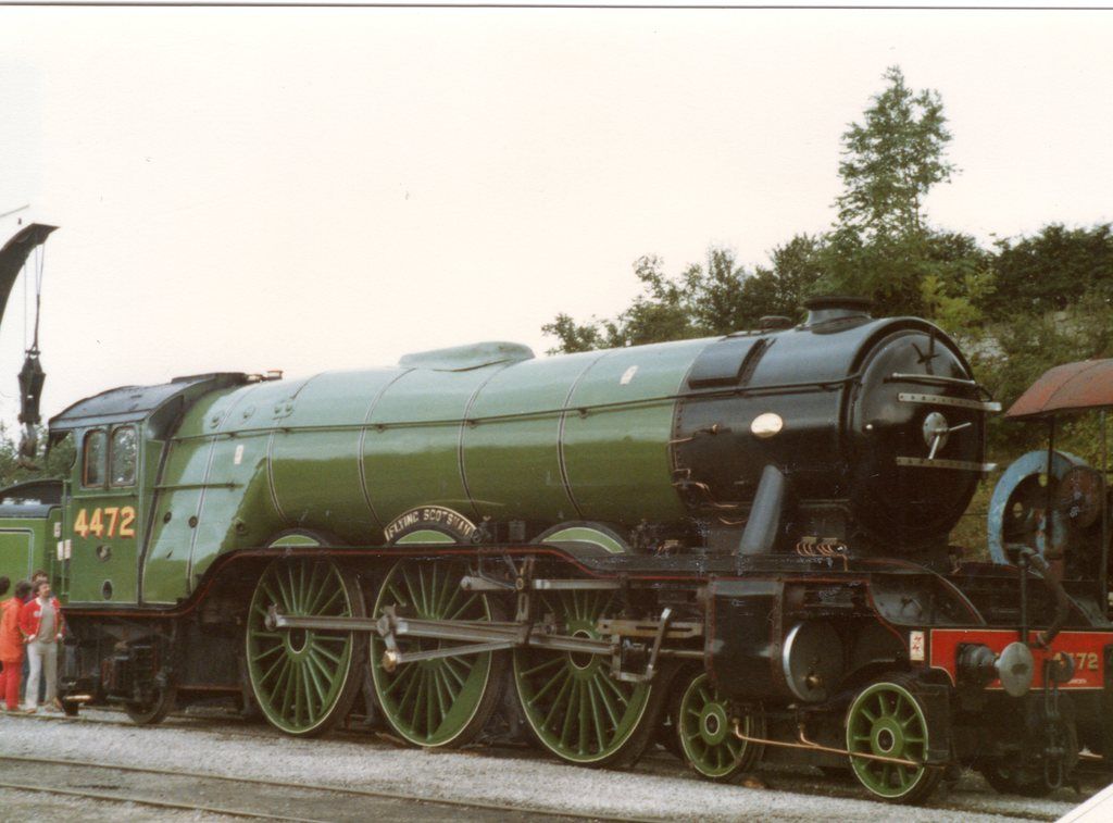 |
|
|
|
Post by Deleted on Oct 23, 2016 8:00:53 GMT
Thanks everyone.....I did say in my reply to Eddie that I concede the steps are a mistake, I'll remove them later. I am aware that the stocks are black, it was LNER practice to paint the loco buffers black, red is BR.
Pete
|
|
davidk
Active Member
Posts: 32
|
Post by davidk on Oct 23, 2016 8:51:20 GMT
Paul, you're absolutely right, the steps are fitted in the 2003 picture. I should have looked more closely...
David
|
|
|
|
Post by Deleted on Oct 23, 2016 16:45:21 GMT
Evening all, thanks to Eddie for his timely intervention I have removed the buffer steps, not sure why I fitted them as they are clearly absent from all of my reference photos for my chosen era. My memory can be a pain at times, this being such a time as I do now recall discussing these steps before, anyway, all sorted now and thank's Eddie for keeping me on track. I have also taken another look at the profile and may revisit this at a later stage as I may add more radius to the outer ring, no need, for now, though, I'll take another look at it when I take everything apart for painting, as long as I remember that is...lol For now here's a picture to keep things on track of the buffer stocks minus their steps...  cheers Pete |
|
|
|
Post by springcrocus on Oct 24, 2016 7:37:47 GMT
Morning Pete,
Just done a catch-up on your build and must say it's looking first class. Loving the old photos of FS as well as your own well-shot pictures of the build. Temporary setback with the buffer treads but, hey, wouldn't life be boring if everything went to plan. Keep it coming...
Regards, Steve
|
|
|
|
Post by Deleted on Oct 24, 2016 7:52:07 GMT
thank's Steve These things are sent to trial you as my late grandmother used to say, onwards and upwards...  Love your own update this morning, very impressive sir.... regards Pete |
|
Midland
Elder Statesman
Posts: 1,870
|
Post by Midland on Nov 1, 2016 20:30:42 GMT
Well GG, all that fuss over a couple of little steps. What I like about the Midland liveries is that the local chap did his own. Weatherburn at St Pancras, Smyth at Nottingham and Pollet at Leeds. All had a free hand. If they wanted a couple of steps on, on they went and if the next chap wanted them off, off they went. So your loco could have been at a certain shed with steps on and then another with them off. We must relax and dream a little. You have no idea what we will find when we uncover the "Strageic Reserve" as it is known in Yorkshire!
Cheers D
|
|
|
|
Post by Deleted on Nov 1, 2016 21:09:07 GMT
haha, you brought back fond memories calling me 'GG' David, it's a long story but I was (and still am) known by that name across the globe, have been for many years.... I'm sure many things changed during a locomotive's career and as you say different sheds did different things, even in the LNER. As for the steps though that was a silly mistake as I have plenty of research material to show that 4472 never had them in LNER days...oh well, let's hope I don't waste much more time on unneeded items. Currently, I'm making small hinges for the upper running board covers and have fitted the centre running board that sits in front of the saddle, having fun as per usual.... regards Pete..aka...GG.. |
|
|
|
Post by Deleted on Nov 2, 2016 16:49:23 GMT
Hi all This isn't so much an update but a plea for information, does anyone have a works drawing that shows a plan view of the smokebox running board? I have been working on this area and after making said board to Don's drawing have noticed in my reference photo's that there's a hatch in the board that's offset to the left hand side and I want to include this is my model. Here's a picture of the board on my model that I'm referring too, having discovered said hatch I now need to modify this board.  Here's 4472 in 1929, an image taken from the film of the same year'Flying Scotsman' which clearly shows the hatch and also of note the row of bolt fixings down either side of the frames, both of which are not shown on Don's drawing.  Flying Scotsman today....  Now I could possibly work out the info that I need from the reference photo's I have but if by chance anyone has a works drawing or photo looking directly down on this area it would help me greatly. Kind regards Pete |
|
jma1009
Elder Statesman
Posts: 5,901
|
Post by jma1009 on Nov 2, 2016 23:35:47 GMT
Hi Pete,
There is obviously a sliding panel on the vertical section of the between the frames front footplating. I cant say whether this was as per originallly built or a later addition. Your hinged flap on the horizontal section may have been before the sliding section. In both cases I would see no other reason for same other than to grease the conjugated motion pins/bearings.
You will need to oil these points. Whatever you decide these oiling points must be easily accessible to achieve this. This would easily be accomplished by making the between the frames footplating removable as a unit.
Cheers,
Julian
|
|
|
|
Post by Deleted on Nov 3, 2016 8:05:32 GMT
Hi Julian
Yes both panels, the horizontal and now the top hinged panel will most likely be for maintaining the 2:1 lever and it's pin. The vertical flap I did cover in more detail when built, from memory it was originally a plain open oval hole which suffered from ash getting into the 2:1 mechanism and so the hinged door was added. The sliding door that we see today was added much later, I can't remember the details but perhaps I wrote it down in this build thread somewhere.
The newly discovered hinged top panel is most certainly for maintaining the same mechanism as the horizontal, this assumption is given more credence by the fact that the panel is offset sitting directly over the 2:1 pivot bearing and pin. I suspect that this allowed easier access to the pin/bearing, not just for routine maintenance but also for replacement when required as it would be relatively easy to lift the pin straight up out of the panel without needing to remove the whole smokebox running board.
cheers
Pete
|
|
|
|
Post by Deleted on Nov 3, 2016 16:50:22 GMT
Evening guys Well, no drawing came forth so I have scaled the door from the photo's that I have to hand, working out the width was easy enough as I have the photo that looks straight towards the front so I can scale the width pretty accurately . The depth is a little more problematic as the only photo's that I have are at angles from the front, however the picture that I posted of the still from the 1929 film came to my rescue as I can see both the smokebox running board and the side running board doors and thus could take a line across from the back of the smokebox door and see where it met the side board door. This is close to half way of said door which happens to be roughly where the back of the 2:1 gear stay ends so I took this as a good omen and modified the panel accordingly. Picture shows progress so far, I now need to get the other upper running board to the same state as the one that's in position and then that lovely tedious job of drilling/csk and tapping yet more 10 BA holes. The plan is to do most of them using short csk 10BA screws but also a small number that go straight through the 10x5mm steel uprights and tapped into the running board below to hold in position. oh and I still need to make two more hinges.... BTW the new door is made from brass as it was the only material that I had to match the 1.2mm steel panel.  More soon Pete |
|
|
|
Post by Deleted on Nov 18, 2016 16:11:26 GMT
Afternoon everyone two weeks since my last update? this just will not do, I haven't done much in that time being a little preoccupied elsewhere but I have done the hinged access panels which I have to say I'm glad to have them done now, lot's of work in such small things but important none the less. I have covered how I make hinges before when doing the tender lockers so won't go through the basics but these ones I tackled a little differently. The length of tube soldered to a similar length of flat stock and then cut up into blocks close the required hinge width was done the same as before. This time though I wanted to ensure that all were the same with the same spacing for the mounting holes , same goes for the holes in the running board, they needed to be identical. Simple enough if using a jig and so choosing a length of stock of the desired width I first machined across said width with a small ball nose cutter creating a recess for the tube section of the hinges. I then drilled 4 holes equally from this centre line, two either side for the mounting hole positions. I didn't take a picture of this but it's clear to see in the following descriptions, note that I used a relatively thick bar stock to ensure that the holes when transferred, didn't move while being drilled. Ok, so the first picture shows the jig being used for the upper running board flap, the running board is held flat on some wood with the flap positioned and held by a clamp which also holds the jig. The position for each hinge was plotted from the outer edge of the opening, I just chose what looked right for hinge size to flap size and pictures to hand. There is a centre line scribed on each side of the jig to line up with the joint to keep the hinge central. Note that the holes look a bit off square, they are this side but not other, result of drilling so deep with a 1.4mm drill (10 BA tapping size) using a blunt drill bit. Makes no difference for this job, I received my order for new bit's today after doing the work...lol Before drilling, a square was used to ensure that the jig was aligned correctly...  I then needed to repeat this process for the other hinges, 10 in all. For the centre board I just removed it and used the same method as for the upper boards but for the main boards I decided to do the drilling in situ, purely as I didn't want to spend hours taking everything apart when I could see a way of doing this with the boards in place. Picture shows the jig once again being held in position, this time you can see the scribed line that ensures the hinge is central. This took a bit of work, well the whole job took some time but these a little longer having to reposition clamps for each hinge, still it worked fine and i was happy with the result. The square bar clamped in the middle was to hold the flap in place and level for drilling through the jig.  Next job was to drill the corresponding holes in each of the hinges, these need to be 1.8mm for clearance but for now, I drilled them at 1.4 through the jig as I still need it at 1.4mm. This time the jig was turned over and used to hold each hinge to a piece of wood with the aid of two clamps. You can see a hinge being held thus in the next picture, note that at this stage the hinge is wider than the jig, this will be dealt with next.  With the holes drilled it was time to get all of the hinges to the same width, going back to the jig the holes were first tapped 10BA and then each hinge was held tightly in place via csk screws, it was then a simple exercise of filing down each edge using the jig as a button, if the hinges had been made of steel I would have hardened the jig first but saw no need when made of brass. Last job to do here was to clean up with a little filing and the opening of the holes up to the required 1.8mm.  Last picture for today showing the covers all bolted back to their respective running boards, this was a fairly long-winded affair but well worth the effort IMHO, I have left two covers open to show they work, the 2:1 gear stay will need the holes filled along it's front edge which drilled/tapped there before I realised that there was a cover here.  So what's next? well, I think while I'm in this area I may as well do the lamp iron,s I have already started to cut metal. I had thought that I wouldn't need to do the grab rails, thinking that they may be a later BR addition, they certainly aren't on Don's drawing and nor have I seen them on any of my reference photos taken during the 20/30's but a new photo that's turned up(new to me) that shows 4472 as in the late 30's, certainly after 38, shows very clearly that the grab rails were present for my chosen era....One thing I do know is that I have a million and one jobs left to do just making good on what's been built so far, certainly a hell of a lot of work before she's ready for paint..., oh well! yet more work:) More soon guys.... Pete |
|
61962
Seasoned Member
Posts: 129
|
Post by 61962 on Nov 18, 2016 22:55:33 GMT
Pete,
Before you go filling holes just check your reference photos. I think there were three hex head set screws in that front plate to keep it closed. It wasn't opened up very often as there were no daily oiling points underneath. Greasing the 2 to 1 gear was on a mileage basis and was a fitters job, and in any case the grease nipples were not accessed from the top. The flap would be lifted only for maintenance purposes, normally at piston and valve exams when the 2-1 centre pin would be removed to slide the levers to each side in turn when the outside cylinder valves were removed.
Eddie
|
|


 Love your own update this morning, very impressive sir....