|
|
Post by delaplume on Feb 18, 2019 1:59:12 GMT
Yes-------I'd agree with that approach also
|
|
|
|
Post by Cro on Feb 18, 2019 6:37:39 GMT
Hi Alan, That sounds about right. I've got the Works Drawings of the injector and non-return outlet valve which is what the body is taken from. There are variations between the two injectors fitted on 1501 at the moment and also to the Works Drawings. I'm not going to stress about that, I expect it would look different again if I looked at it again in a year or two. The model below has gone through many iterations to get the proportions to look more like the real thing. I've also added an M8 x 0.75 (fine) threaded attachment with an O-ring instead of the four M1.4 bolts which are not really practical. The question is, should I put a short extension to the inlet and fit a Brass gauze finger as a filter? [Snip] Now that will be a very intricate exercise in CNC machining unless that nice Mr Cro felt like making some lost wax castings of them for us less clever blokes? Every GWR engine needs a pair, although perhaps only easily visible on pannier tanks... A filter is definitely needed, and the gauze finger sounds a neat way of doing it. You shouldn't need to be too concerned about having to unblock them in the pits though; if your water is so filthy as to clog them, you will have your work cut out cleaning the tanks anyway. They are very like marine seacocks when seen in your sectioned view, and those too are always tapered, but using PTFE and a lot of care your parallel plugs will be more straightforward to manufacture- proprietary model tender water cocks are made that way, and without the benefit of the O-rings in your drawing. Looking forward to developments! -Gary The injectors or the valves? Or both?! Got injectors but only as printed waxes so they were £££££ I'm working with a friend on a more reliable working 10x and once we have finalised that I'll be tooling up to make them for a heck of a lot less! The valves look simple enough and will see if I can look into them I just need work to stop sending me everywhere! Love the detail Roger, would it be simpler to fit the filters on the inlet of the tanks which can just be slid out the filler rather than take all that pipework off to clean a filter at the bottom? Adam |
|
|
|
Post by Roger on Feb 18, 2019 8:08:52 GMT
I'm thinking of the finger filter as being a last line of defence, I hope to fit larger ones in the tank, perhaps partitioning off one end with a mesh wall? I have to bear in mind that the water might also be coming from the riding truck, so that will need a filter too. I might fit one on the outlet of the axle pump. That could be very fine since it wouldn't rely on gravity or suction to draw the water through.
The valves should be easy enough to seal with PTFE barrels. I did toy with using 'O' rings on each end, but the one that's furthest from the shaft would need special fitting tools if it was on the barrel because it would probably get chopped in half when it was pushed past the holes in the barrel. Having said that, a large enough 'O' ring might work on that end. I might just take a look at that again.
I'm not sure how the injectors will be made yet, there's still a lot of internal design to be done. The most likely method is to machine them in two halves then Silver Solder them together. The main bore would be finish machined after that operation, as would the flanges. It's not particularly difficult to do with a bit of thought and a couple of fixtures.
|
|
|
|
Post by terrier060 on Feb 18, 2019 14:51:29 GMT
Hi Alan, That sounds about right. I've got the Works Drawings of the injector and non-return outlet valve which is what the body is taken from. There are variations between the two injectors fitted on 1501 at the moment and also to the Works Drawings. I'm not going to stress about that, I expect it would look different again if I looked at it again in a year or two. The model below has gone through many iterations to get the proportions to look more like the real thing. I've also added an M8 x 0.75 (fine) threaded attachment with an O-ring instead of the four M1.4 bolts which are not really practical. The question is, should I put a short extension to the inlet and fit a Brass gauze finger as a filter? 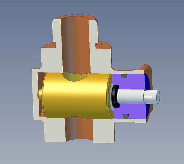 Injector water valve Injector water valve by Anne Froud, on Flickr The inside looks like this, with a pretty shallow bush that will be made from Phosphor Bronze since they're thin. Those will be Silver Soldered in place. I've moved them slightly further apart than the Works Drawings show so that I can unscrew them. The peculiar elbow will be machined in two halves and Silver Soldered together. 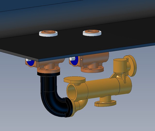 Injector water inside arrangement Injector water inside arrangement by Anne Froud, on Flickr So this is the overall look on the model... 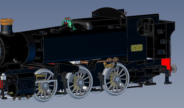 Side view Side view by Anne Froud, on Flickr ... and this is how it looks on 1501. 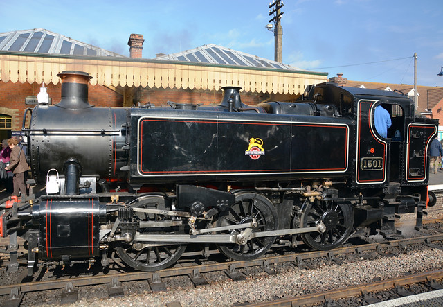 37567973140_c3be406d44_o 37567973140_c3be406d44_o by Anne Froud, on Flickr Have a look at my thread Roger - Page 8 - it may be of some help. I may have other images I can send you if you are interested. I was servicing one of these on the SDR last year or the year before. Ed |
|
|
|
Post by Roger on Feb 18, 2019 15:03:44 GMT
Thanks Ed, that injector looks pretty much the same as the ones on 1501. Although mine will be cosmetically similar, that's where the similarity ends. The 'aligator' type of split combining cone isn't really practical, hence the axially split type. I do have some excellent pictures (below) of a miniature one with two valves, I think Don posted those, and that's the arrangement I think I'll end up using. 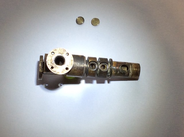 3Y4muaA 3Y4muaA by Anne Froud, on Flickr This is a very clever arrangement indeed. You'll notice that it has two non-return valves which enables it to work with water at an elevated temperature. 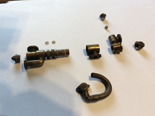 SAGCdA8 SAGCdA8 by Anne Froud, on Flickr |
|
|
|
Post by Roger on Feb 18, 2019 18:55:39 GMT
Ok, time to machine the injector water valve bodies. Although it's possible to machine the whole shape including the flanges and threaded part, it requires a large piece of material and a lot of machining. Instead I've decided to chop off the flanges on the model temporarily and add a registration hole in each side to locate separate flanged pieces which will probably have to be finish machined before hand due to the difficulty of holding it firmly enough for screw cutting. I've extended the body on the RH side of this so that there's enough room for a large cutter to come in behind the webbed section. That makes it easier when switching to smaller cutters to finish it. I've also added 0.3mm to the faces where the webs finish flaring out. Those will be machined off when it's turned through 90 degrees. I've don that to give the software and cutter a flat face to end on which should make life easier and not end up with a whispy edge.  Top side for machining Top side for machining by Anne Froud, on Flickr The CAM zero is on the centre line of the bore, not the centre of the part. That's because it's easier to return it to the lathe later and bore the hole, knowing it's on the centre line of the stock which I clock up on to start with. This is the first operation, Horizontal Roughing which has been told that the stock is 16mm square. Sadly, the software isn't smart enough to tell it that it's round stock, so it's going to waste time cutting a fair bit of fresh air to start with. This is why you want to crack on with that operation and get the bulk of the material gone in one hit. You can see some of the wasted motions described by the blue cutter centre lines on the model below. 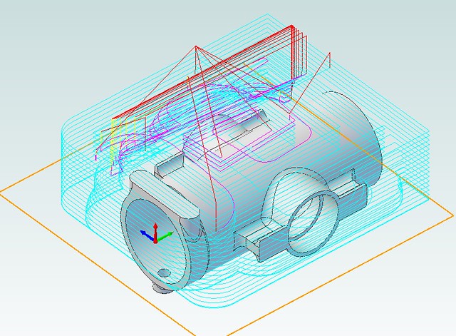 Top side Horizontal roughing Top side Horizontal roughing by Anne Froud, on Flickr Here's my quick 'sanity check' to make sure that it's going to clear the chuck (just) when it's at the extreme right and full depth. A miss is as good as a mile! 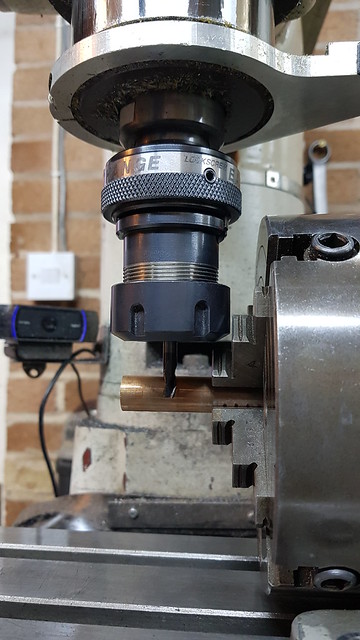 20190218_161243 20190218_161243 by Anne Froud, on Flickr I include this shot to show that I really don't care about whether the cutter is re-cutting swarf or not. It's really of no consequence on most jobs, especially when roughing out. This is how it looked after the complete unattended rouging operation... 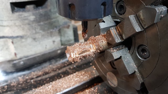 20190218_175124 20190218_175124 by Anne Froud, on Flickr ... which looks like this. The cutter is a Carbide 5.5mm diameter 3-flute of which I have many from the various shows I've visited recently. The feed is 50mm/min at 1350RPM and 0.5mm deep with a 50% step over. You have to remember that the deeper you go with each step, the coarser the shape you end up with, and all that extra material has to be machined off with a smaller cutter. It's a compromise that you have to play around with to get the job done without unnecessarily long run times. The big issue is how to get into the concave areas in as few steps as possible so you can get into the tight corners with the smallest cutter required. Stepping down in two or more cutter sizes is sometimes necessary, and restricting machining only to those tight areas is one way to save machining the whole thing with a small cutter too soon.  20190218_175151 20190218_175151 by Anne Froud, on Flickr |
|
JonL
Elder Statesman
 WWSME (Wiltshire)
Posts: 2,907
|
Post by JonL on Feb 18, 2019 19:19:31 GMT
For the times when you do care about the presence of Swarf I still think the flexible hose leading from a decent aquarium pump would probably be enough to keep it pretty well dusted.
|
|
|
|
Post by David on Feb 18, 2019 21:39:12 GMT
Do you have a quick way of setting up your chuck in line with the Y axis or do you just use an indicator?
I'm surprised your software doesn't allow you to specify round stock. For something that costs so much and I assume is pretty mature that seems like a useful feature to be missing.
|
|
|
|
Post by Roger on Feb 18, 2019 22:16:39 GMT
Do you have a quick way of setting up your chuck in line with the Y axis or do you just use an indicator? I'm surprised your software doesn't allow you to specify round stock. For something that costs so much and I assume is pretty mature that seems like a useful feature to be missing. The chuck axis is in line with the X-axis as it happens. I just use a square on the base for things like this because the distance along the piece is so small that it doesn't have to be micron perfect. It's much more important to clock the stock as good as you can get it. It it's not round, I'll turn a short section to make sure it is. It makes life so much easier if you can rely on the stock to be central. I touch down on the stock and set the DRO to the radius. The wobbler is used on the front and back of the stock, judging the height to be roughly on the centre line by eye. The height doesn't have to be accurate so long as it's the same when you touch the back with the wobbler. I then halve the distance. Then I touch the end and set the DRO to the -ve radius of the wobbler ball. It takes a few minutes, but it's easy enough. I know that Fusion360 didn't have shaped stock last time I looked, but maybe it has it now. I don't know whether the more expensive licences of Alibre have it, but I doubt it. It's just something you have to live with until they get their act together and implement it. You have to bear in mind that most milling jobs are from rectangular blocks, what I'm doing is a bit unusual. There are a lot of things that would be useful that are missing, but you have to live with what you can afford. I doubt if there's any software out there that ticks all the boxes. If you have too many features, the whole thing can be bewlidering. Sometimes keeping it simple isn't such a bad thing. I doubt in many users of Fusion360 have the faintest idea about what half the CAM functions do. |
|
|
|
Post by nick952 on Feb 18, 2019 22:25:38 GMT
Roger,
You should have the option for "cylindrical Stock" (and some others), but you have to select it. from the Stock dropdown menu in the Program Tab, or RMB click on "Stock" in the tree. The option is available in all levels of AlbreCam above Xpress.
|
|
|
|
Post by Roger on Feb 18, 2019 22:45:54 GMT
Roger, You should have the option for "cylindrical Stock" (and some others), but you have to select it. from the Stock dropdown menu in the Program Tab, or RMB click on "Stock" in the tree. The option is available in all levels of AlbreCam above Xpress. Hi Nick, I can't see that anywhere. In the Program tab of the CAM module I've only got options of 'Box Stock' or 'Part Box Stock', nothing else. I'm using the integrated Mecsoft CAM module VisualCAM 2015 which shows the tool paths within Alibre, superimposed on the 3D model. I've had a good look on the internet and I can't find any reference to it, so maybe you're using a different product to mine? |
|
jma1009
Elder Statesman
Posts: 5,901
|
Post by jma1009 on Feb 18, 2019 22:53:17 GMT
This is going to be fun, and I hope many forum members will get glued to Roger's injector making and associated bits!
Cheers,
Julian
|
|
|
|
Post by Roger on Feb 18, 2019 23:00:36 GMT
The second operation on the underside is using a 2mm diameter Ball nosed cutter to start getting deep into the concave areas. Doing this with a Ball Nosed tool with a short flute length and 0.25mm deep cuts means it can be done fairly quickly and get somewhere close to the finished shape. This is leaving 0.15mm still to go. Using a Horizontal Finishing operation means you don't suddenly dig in, you're always cutting no more than 0.25mm deep, whatever the shape is. If you tried this with a Parallel Finishing operation it would dive into the concave areas where there was a lot of material left from the previous roughing cut. I ought to have mentioned on the previous post that I set the bottom depth to -0.5mm to make sure the cutter just passes the middle but doesn't try to dive down to the bottom of the model! 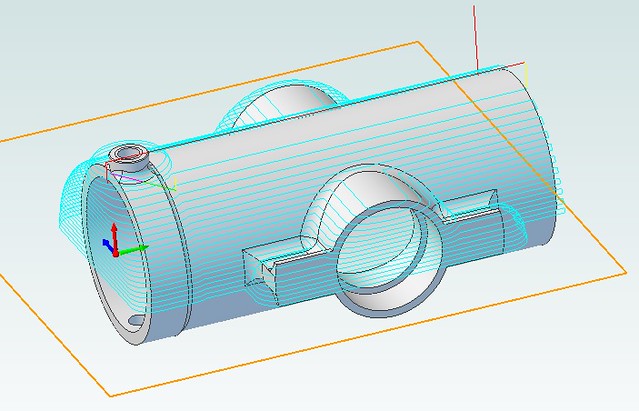 Bottom side horizontal finishing Bottom side horizontal finishing by Anne Froud, on Flickr And this is the result of that on the bottom side. There isn't time to do the top today so I'll leave it set up with the Servos live and start it off again in the morning knowing it's exactly how I left it with the cutter set at the same height as the other side. 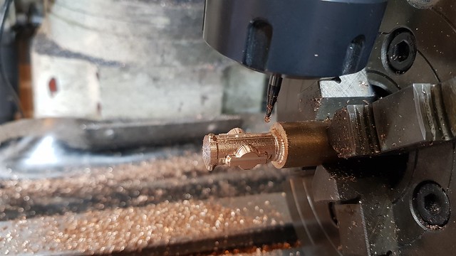 20190218_224641 20190218_224641 by Anne Froud, on Flickr |
|
|
|
Post by nick952 on Feb 18, 2019 23:08:12 GMT
That explains it, I thought that you had updated to the newer MecSoft AlibreCam, after the change back from Geomagic Design, to Alibre Design.
|
|
|
|
Post by Roger on Feb 18, 2019 23:46:46 GMT
That explains it, I thought that you had updated to the newer MecSoft AlibreCam, after the change back from Geomagic Design, to Alibre Design. I've been resisting the change, it's so expensive to update. I try to hold out for as long as possible because they rarely introduce features that I want and they never seem to fix the bugs I complain about. Usually they come up with some sort of 'amnesty' to make it cheaper to get back onto 'maintenance'. It's not maintenance really, the thing is still full of holes and crashes way too often for my liking. |
|
Gary L
Elder Statesman
Posts: 1,208
|
Post by Gary L on Feb 19, 2019 1:31:29 GMT
Now that will be a very intricate exercise in CNC machining unless that nice Mr Cro felt like making some lost wax castings of them for us less clever blokes? Every GWR engine needs a pair, although perhaps only easily visible on pannier tanks... A filter is definitely needed, and the gauze finger sounds a neat way of doing it. You shouldn't need to be too concerned about having to unblock them in the pits though; if your water is so filthy as to clog them, you will have your work cut out cleaning the tanks anyway. They are very like marine seacocks when seen in your sectioned view, and those too are always tapered, but using PTFE and a lot of care your parallel plugs will be more straightforward to manufacture- proprietary model tender water cocks are made that way, and without the benefit of the O-rings in your drawing. Looking forward to developments! -Gary The injectors or the valves? Or both?! Got injectors but only as printed waxes so they were £££££ I'm working with a friend on a more reliable working 10x and once we have finalised that I'll be tooling up to make them for a heck of a lot less! The valves look simple enough and will see if I can look into them I just need work to stop sending me everywhere! Love the detail Roger, would it be simpler to fit the filters on the inlet of the tanks which can just be slid out the filler rather than take all that pipework off to clean a filter at the bottom? Adam Hi Adam The valves, primarily. They are intricate and distinctive in shape, while being very simple in function. More to the point, there is nothing remotely suitable on the market at the moment (tender water valves do the job, but can't be mounted in this location); so if you want to do the job properly you have to make your own. The 'works' are fairly straightforward, but getting them to look right as well is very difficult, unless you are Roger! Paired with a 'scale' injector would be the bees knees for appearance, but personally I would be prepared to compromise on the injector, in favour of the proven reliability of the traditional model engineer's pattern. There is a little bit of form v function here, I think, and quite a lot of £££ as you mention! WRT filters... not really. Screening the incoming supply is always a good plan, but water that was clean at first, might not still be clean if it has festered in the bottom of a tank for a month. Rainwater, in my experience, which many clubs use, is particularly prone to developing organic growths in storage, so you can't really do away with a filter screen immediately upstream of the injector. -Gary |
|
|
|
Post by David on Feb 19, 2019 1:48:52 GMT
F360 allows you to set the stock to a box, cylinder, tube, or a solid from the model. I used this last one when I rounded the edges of the sandboxes - I made a copy of the sandbox body, removed the chamfers, and used that as the stock shape. Obv the cylinder one is good for part-on-a-stick. The stock can be fixed size or relative to the model although I'm struggling to see how you could use that last one except by lucky coincidence.
F360 has a very confusing number of toolpath operations, its sketch operations and constraints can be difficult and I've never managed to get anything useful out of its drawing mode. But given I didn't pay for it it's pretty good going. I guess a professional gets to know all the tricks but for hackers like me it can take a long time to make it do what you want! And as that dialog in my mogul thread shows even a simple profile toolpath has a huge number of settings. I ignore almost all of them but it can take some time to get 'rest machining' to work.
So I'm sure all CAD/CAM systems have their good and bad points.
Your water valve body looks great and I'm looking forward to the time I can do something similar.
|
|
|
|
Post by Roger on Feb 19, 2019 8:03:06 GMT
F360 allows you to set the stock to a box, cylinder, tube, or a solid from the model. I used this last one when I rounded the edges of the sandboxes - I made a copy of the sandbox body, removed the chamfers, and used that as the stock shape. Obv the cylinder one is good for part-on-a-stick. The stock can be fixed size or relative to the model although I'm struggling to see how you could use that last one except by lucky coincidence. F360 has a very confusing number of toolpath operations, its sketch operations and constraints can be difficult and I've never managed to get anything useful out of its drawing mode. But given I didn't pay for it it's pretty good going. I guess a professional gets to know all the tricks but for hackers like me it can take a long time to make it do what you want! And as that dialog in my mogul thread shows even a simple profile toolpath has a huge number of settings. I ignore almost all of them but it can take some time to get 'rest machining' to work. So I'm sure all CAD/CAM systems have their good and bad points. Your water valve body looks great and I'm looking forward to the time I can do something similar. I think Fusion360 is way more advanced than the Alibre/Mecsoft combination I've got. Even so, there are still quite a few features of the CAM I can't ever see using, but you never know. Now I know about the round stock feature in the latest CAM module, I at least have a good reason to upgrade when an affordable path to do that comes around. For the time being, it just takes a little longer so it's not a huge deal. I guess stock shape based on the 3D model is intended for machining castings? I think it's a good idea, although it won't get used that often. What would be more useful would be to have the option to create a 3D model of the stock and be able to place the part model anywhere within it. The one thing I do like about Mecsoft CAM over Fusion360 is actually a negative thing most of the time. That's the way you can simply define specific cuts based on open or closed sketch lines. Fusion360 is very smart, it works the way I expected Alibre to work and I was disappointed to see how clunky Alibre is with its CAM. However, that can be really useful in controlling exactly what's going on. I'm sure there are ways to generate say a partial cut that follows an open sketch in Fusion360 though. You'll find the valve easy enough to machine when you get round to it. Avoiding vertical surfaces, controlling where the tool paths go, and choosing a good machining strategy are the key steps. It's great fun! |
|
|
|
Post by Roger on Feb 19, 2019 18:00:59 GMT
This is the reverse side getting the Parallel Finishing treatment... 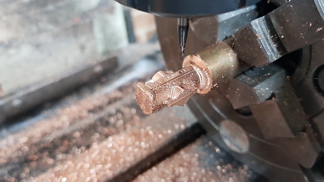 20190219_092636 20190219_092636 by Anne Froud, on Flickr ... but I did manage to break a cutter because I hadn't told the previous pass to 'clear flats' and that left the boss on the left too high for it to machine off at the rate I was cutting. This is the fine finishing pass... 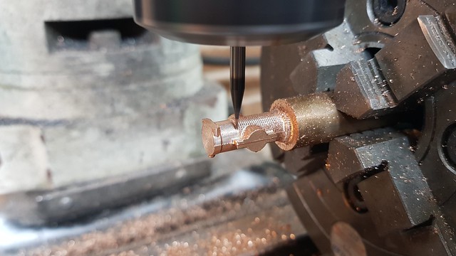 20190219_134924 20190219_134924 by Anne Froud, on Flickr ... which I decided to change to use 50microns overlap else the finish was too rough. That's an issue with having to use small diameter cutters to get into the small concave areas, there's a tight radius on the ball nose so you get a rougher finish. So this has taken all day while I've had to do my Corporation Tax Return for the first time without an Accountant. How do those people summon the energy to get out of bed and do a job like that, it would kill me. 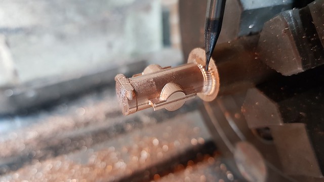 20190219_162200 20190219_162200 by Anne Froud, on Flickr |
|
|
|
Post by delaplume on Feb 19, 2019 18:29:45 GMT
Hi Roger,
Quote}---"So this has taken all day while I've had to do my Corporation Tax Return for the first time without an Accountant. How do those people summon the energy to get out of bed and do a job like that, it would kill me"....
They're called}-----"Civil Servants"........It's been my lot to have been exposed to, or involved with them in one form or another all my working life.........Grim is one way of looking at it............You learn to develop a sense of "Humour" very early on as a form of self defence..........To some I may appear churlish, flippant or even the word puerile has been flaunted, but that's where it stems from................
It was very similar on board HM ships, which was like doing "Porridge" only in a bouncy prison ie}---- your immediate world is confined to set parameters ( the ship )....there are the "Screws" ( The commissioned Officers ), ....the inmates ( the rest of the crew )....a pecking order ( the ranks )....your sentence ( the time at sea )....etc, etc..Your daily routine is predictable and ordered....
I imagine it must have been the same for Army and RAF life in Barracks ??.........so just as in Porridge you look for those little, daily "Victories" to help the time go by.......
Oopppssssss........here endeth the lesson !!
|
|


