|
|
Post by andyhigham on Feb 22, 2019 10:52:49 GMT
I would have no qualms about turning a loco out with a "Hot rod flames" or similar paint job. Just to upset the rivet counters and miserable old farts
|
|
mbrown
Elder Statesman

Posts: 1,718
|
Post by mbrown on Feb 22, 2019 11:12:38 GMT
Completions aren't just about total authenticity to prototype - if they were, no working loco would get far. They're also about workmanship, appropriate choice of material and so on.
But even if you don't enter competitions, Roger, I do hope you'll exhibit 1501 frequently - people will be inspired by seeing it in the flesh (metal) even more than by this thread. That would be a valuable service to the whole hobby.
Malcolm
|
|
|
|
Post by flyingfox on Feb 22, 2019 12:11:59 GMT
I have always found the best way to deal with the "helpful critic" is to ask to see one of their models, and then watch them run off.
Something along the lines of "that's very interesting, can you show me one of you models please", works well.
Every person who has slaved away to produced a finished locomotive deserves nothing but praise & plenty of it.
Keep up the good work.
Regards
Brian
|
|
|
|
Post by Roger on Feb 22, 2019 12:43:42 GMT
Great sentiments, I love it! I especially agree with Brian's comment "Every person who has slaved away to produced a finished locomotive deserves nothing but praise & plenty of it." Making stuff is an absolute joy, regardless of the quality of workmanship, and I really enjoy seeing anything and everything someone has had the drive to turn into a physical reality.
I do intend to exhibit 1501 eventually, it gives an excuse to meet up with like minded souls and chew the fat.
|
|
|
|
Post by Roger on Feb 22, 2019 16:17:32 GMT
Rather than waste this bar end of Phosphor Bronze, I'm Silver Soldering it to a piece of Mild Steel so I can hold it in the chuck to make the outlet flanges for the Injector Water Valves...  20190221_172521 20190221_172521 by Anne Froud, on Flickr ... here seen fluxed up and a piece of Silver Solver Wire wrapped around it for a start, it's going to need a bit more than that.  20190221_173245 20190221_173245 by Anne Froud, on Flickr Some other bar was used for the flanges that go on the Side tank. These are similar to the backhead fittings ie they are fine threaded (M8 x 0.75) and a 1mm section 'O' ring used to seal on the diameter. The angular position will be set by the same method, ie very fine trimming of the face. Here I'm measuring the 'O' ring groove which needs to create an annular gap of 0.8-0.85mm for the 1mm section 'O' ring. 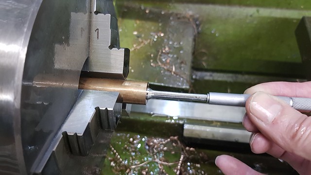 20190222_112157 20190222_112157 by Anne Froud, on Flickr It's easier to tap, machine the bore and then reverse turn the location diameter to fit the Side Tank body all from this one setup then part it off. I've got a short mandrel to sit it on the other way round for facing to length. 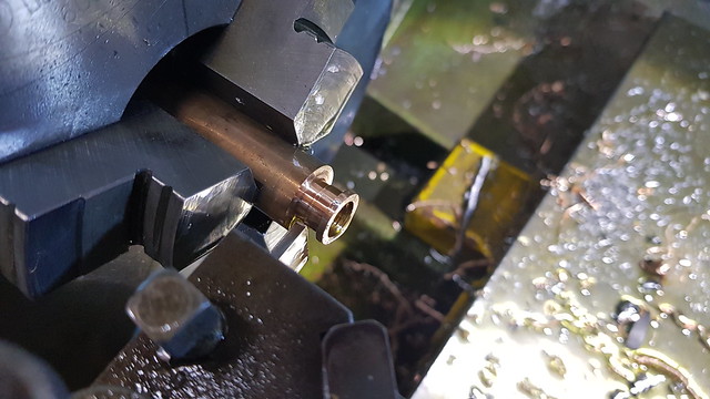 20190222_113529 20190222_113529 by Anne Froud, on Flickr This is the rough way to set the boring bar to the right size. Just touch the back of a measured diameter and tell it that it's negative that size. It won't cut precisely to size in the bore, that still needs to be measured, but you can get very close. 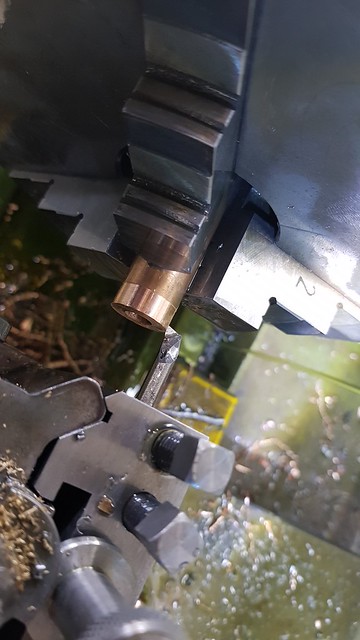 20190222_114620 20190222_114620 by Anne Froud, on Flickr The idea is to keep this on the stock for as long as possible because it's not easy to hold. The outlet flange is shown in position, both are going to be held together by the Mild Steel rod which I'll thread at the appropriate length to take the M4 nuts. The cross hole will eventually end up being 5mm diameter, so I wanted to use something soft that could easily be machined away when the Silver Soldering is done. The flat on the back of the stock is so I can clock it up true again. So here are both the outlet flanges which will have the M1.4 holes for the studs added when it's finished on the mill. There's no point in trying to add them now, it just makes life harder later on. The threaded bushes will be Silver Soldered into the tank bottom. They're shallow so that the water can reach the exit hole when the level is very low. Again, the bushes are made from Phosphor Bronze because it's more durable than Brass on such a short length of thread. The bore will be machined last and then the valve can be parted off as virtually complete. 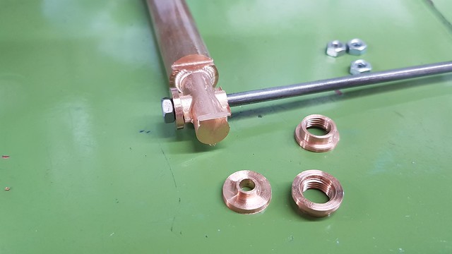 20190222_155922 20190222_155922 by Anne Froud, on Flickr |
|
|
|
Post by 92220 on Feb 22, 2019 17:34:37 GMT
Nice one Roger!!
I like the idea of silversoldering a stump onto a bar to make it able to be held in a chuck. Never thought of that one. That will save my scraps from the scrap bin!
I'm working on my smokebox door at the moment. I needed to silversolder the brackets, that hold the number plate, to the door. I wanted to see what I was doing while silversoldering so wanted to have a realtivly tidy flux coating. A while ago I posted that I had bought a cheap single induction hob from Aldi, for £29.00, with the idea of using it to heat parts for soft soldering. I used it for the first time, in earnest. I made up a jig to hold the brackets in the correct position, and then fluxed them. I put the door in the centre of the induction plate and set it to max heating. The flux gently bubbled and coated the bracket ends and the steel of the door turned blue with the heat. The flux was transparent so I lifted it off and took it to the hearth and used a No3 nozzle in the oxy torch, set to a tiny flame, and very quickly got the brackets soldered in place with a really tiny fillet of silversolder.
When I looked at the hob, and wiped it clean, although the steel had got to a dark blue heat in less than 30 seconds (!), there was not a mark on the surface of the hob. I'm thinking it just might be possible to use the hob to actually heat a job to silversoldering temperature. The hob was cheap enough to risk it to see if it works. That might open up a whole new ball game for silversoldering complicated assemblies because the heating wouldn't be concentrated on one place; it would be all over at once.
I've got some photos. If they have come out OK I'll post them.
Bob.
|
|
|
|
Post by Roger on Feb 22, 2019 18:17:32 GMT
Nice one Roger!! I like the idea of silversoldering a stump onto a bar to make it able to be held in a chuck. Never thought of that one. That will save my scraps from the scrap bin! I'm working on my smokebox door at the moment. I needed to silversolder the brackets, that hold the number plate, to the door. I wanted to see what I was doing while silversoldering so wanted to have a realtivly tidy flux coating. A while ago I posted that I had bought a cheap single induction hob from Aldi, for £29.00, with the idea of using it to heat parts for soft soldering. I used it for the first time, in earnest. I made up a jig to hold the brackets in the correct position, and then fluxed them. I put the door in the centre of the induction plate and set it to max heating. The flux gently bubbled and coated the bracket ends and the steel of the door turned blue with the heat. The flux was transparent so I lifted it off and took it to the hearth and used a No3 nozzle in the oxy torch, set to a tiny flame, and very quickly got the brackets soldered in place with a really tiny fillet of silversolder. When I looked at the hob, and wiped it clean, although the steel had got to a dark blue heat in less than 30 seconds (!), there was not a mark on the surface of the hob. I'm thinking it just might be possible to use the hob to actually heat a job to silversoldering temperature. The hob was cheap enough to risk it to see if it works. That might open up a whole new ball game for silversoldering complicated assemblies because the heating wouldn't be concentrated on one place; it would be all over at once. I've got some photos. If they have come out OK I'll post them. Bob. Hi Bob, That's very interesting indeed, you may well be right about doing the whole thing like that. I really dislike a flame, it's a necessary evil but causes so much oxidation given half a chance. I wonder if the hob would still work if you put a thin sheet of ceramic lagging between it and the part? I just imagine a red hot part sticking to the glassy surface of the hob if it all got red hot. Another thought would be that you could incorporate that in a vacuum chamber to make a furnace for brazing. You might really be onto something here. |
|
|
|
Post by terrier060 on Feb 22, 2019 23:18:00 GMT
Love the work on the injectors Roger - look like some very complicated setups. I have a LOT to learn.
|
|
|
|
Post by Roger on Feb 23, 2019 8:55:06 GMT
Love the work on the injectors Roger - look like some very complicated setups. I have a LOT to learn. Hi Ed, Don't be fooled, this isn't as tricky as it looks. Once you've done one job on its side, you'll see how it pans out. I like that smaller ER collet arrangement, it's something I could use for this sort of job, as well as a smaller rotary table that lets me get in closer with less overhang. |
|
|
|
Post by terrier060 on Feb 23, 2019 9:54:01 GMT
Yes there is no doubt that the one Cutwell sell will be a much better one which is balanced to higher revs, but much more expensive. I suspect the spindle on your lathe is quite large - probably takes 1" stock?
|
|
|
|
Post by Roger on Feb 23, 2019 12:19:53 GMT
Yes there is no doubt that the one Cutwell sell will be a much better one which is balanced to higher revs, but much more expensive. I suspect the spindle on your lathe is quite large - probably takes 1" stock? I doubt if there's much difference between the two in terms of runout. I suspect the only difference is that one's balanced and the other isn't. |
|
|
|
Post by 92220 on Feb 23, 2019 13:21:59 GMT
Hi Roger.
One reason I bought the hob from Aldi is that it was cheap and if I scrapped it, it wouldn't be a an expensive waste of cash. I am actually wondering if the surface is maybe a transparent form of ceramic. The other point is that the manufacturers of induction hobs have to cater for the odd person letting a saucepan boil dry and not sending the electronics up is smoke and causing a fire. A dry saucepan would heat up to red heat in under 3 minutes. A thin insulation sheet is what I had intended but I hadn't been able to find any 6mm Vermiculite, or similar, that is an insulation AND capable of withstanding physical contact with a red hot component.
I know I can get 1" thick but didn't know anyone who has a bandsaw that has at least a 12" throat, to slit it. Then, reading your post reminded me that I HAVE a bandsaw with a 12" throat. It's the Clarke 4.1/2" metal bandsaw that I use for cutting up bar stock. It can be opened wide and a table fitted to use it as a normal bandsaw. Now all I have to do is get hold of some !2 Vermiculite and set up some method of holding it vertical and sliding square to the edge of the blade. Having the insulation will reduce the magnetic field, but hopefully not so much that it won't heat a steel disc. I did experiment with lifting a sheet of steel off the surface and it wasn't until there was a 20mm gap between the hob and the steel sheet, that the hob switched itself off.
I've just had a thought....When I had the paint business I used to sell ceramic fibre insulation 'paper, and blanket. The 'paper' was 1/8" thick. That would be the answer to the insulation problem. I'll get some and check it out. It should be much better than Vermiculite. That led me to remember when it was first marketed, it was advertised that a 4" thickness of ceramic fibre blanket was capable of insulating a blast furnace. When it was shown on BBC Tomorrow's World, many years ago, a guy stood in the studio with a sheet of 1/2" ceramic fibre 'paper' on his hand and someone played a large Seivert gas torch on it! I'll let you know how I get on with trying to get a red hot component.
Bob.
|
|
|
|
Post by Roger on Feb 23, 2019 16:16:22 GMT
Hi Roger. One reason I bought the hob from Aldi is that it was cheap and if I scrapped it, it wouldn't be a an expensive waste of cash. I am actually wondering if the surface is maybe a transparent form of ceramic. The other point is that the manufacturers of induction hobs have to cater for the odd person letting a saucepan boil dry and not sending the electronics up is smoke and causing a fire. A dry saucepan would heat up to red heat in under 3 minutes. A thin insulation sheet is what I had intended but I hadn't been able to find any 6mm Vermiculite, or similar, that is an insulation AND capable of withstanding physical contact with a red hot component. I know I can get 1" thick but didn't know anyone who has a bandsaw that has at least a 12" throat, to slit it. Then, reading your post reminded me that I HAVE a bandsaw with a 12" throat. It's the Clarke 4.1/2" metal bandsaw that I use for cutting up bar stock. It can be opened wide and a table fitted to use it as a normal bandsaw. Now all I have to do is get hold of some !2 Vermiculite and set up some method of holding it vertical and sliding square to the edge of the blade. Having the insulation will reduce the magnetic field, but hopefully not so much that it won't heat a steel disc. I did experiment with lifting a sheet of steel off the surface and it wasn't until there was a 20mm gap between the hob and the steel sheet, that the hob switched itself off. I've just had a thought....When I had the paint business I used to sell ceramic fibre insulation 'paper, and blanket. The 'paper' was 1/8" thick. That would be the answer to the insulation problem. I'll get some and check it out. It should be much better than Vermiculite. That led me to remember when it was first marketed, it was advertised that a 4" thickness of ceramic fibre blanket was capable of insulating a blast furnace. When it was shown on BBC Tomorrow's World, many years ago, a guy stood in the studio with a sheet of 1/2" ceramic fibre 'paper' on his hand and someone played a large Seivert gas torch on it! I'll let you know how I get on with trying to get a red hot component. Bob. Hi Bob, Yes, that ceramic fibre insulation is what I meant, but it needn't be as thick as that. The stuff I've got is about 1-1.5mm thick and probably wouldn't interfere with the transfer of energy. Looking at some YouTube references, it would appear that at least some hobs have a feedback sensor which presumably limits the temperature. Quite how that senses it's not certain, but that might be affected by a thin insulator which might allow the temperature to go much higher. I await with interest to see what you come up with. It would be great to see a piece of Red hot material sat on top of a ceramic mat! |
|
|
|
Post by 92220 on Feb 23, 2019 18:50:37 GMT
Hi Roger.
I've got some thin ceramic fibre sheet coming. I'll let you know how it all works out.
Bob.
|
|
|
|
Post by Roger on Feb 23, 2019 21:52:20 GMT
This is the input fitting for the water valve, with the threaded part and 'O' ring groove.  20190223_101836 20190223_101836 by Anne Froud, on Flickr The threaded bush was screwed on while it could be held tightly... 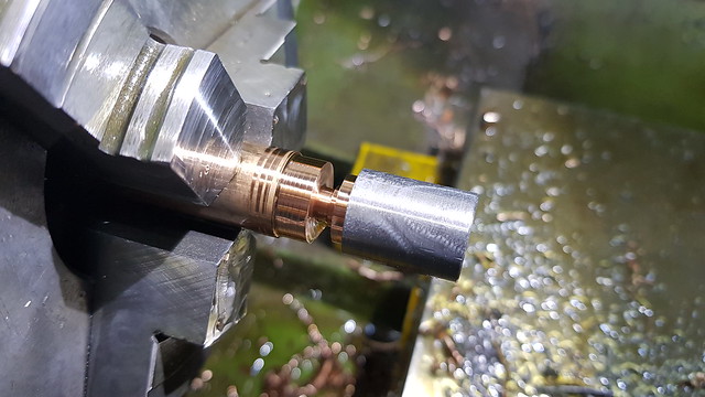 20190223_102033 20190223_102033 by Anne Froud, on Flickr ... then removed with another ER32 EasyChange collet lined up by the spring loaded tapping centre. I find this works really well without causing any damage. 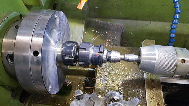 20190223_110422 20190223_110422 by Anne Froud, on Flickr And here are all of the parts awaiting assembly. I've tried an 'O' ring to make sure the fit feels right. 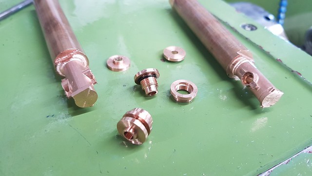 20190223_123005 20190223_123005 by Anne Froud, on Flickr The lineup is guaranteed by the close fitting Mild Steel rod and held in place whatever the orientation when it's hot. 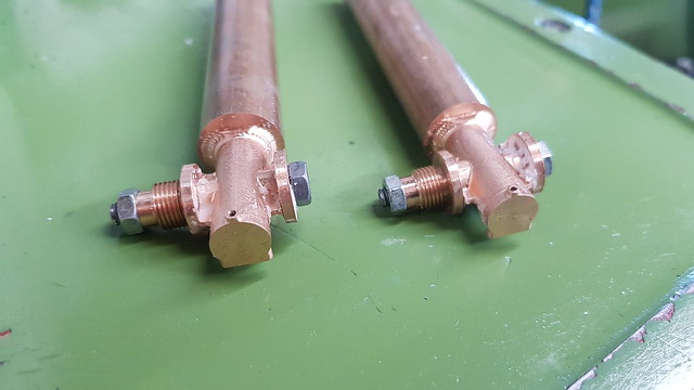 20190223_175216 20190223_175216 by Anne Froud, on Flickr The idea is to only attempt one joint at a time because gravity needs to be used to make sure the Silver Solder flows in the right direction. I've cleaned and covered the thread and 'O' ring groove with Tippex to make sure no Silver Solder leaks onto it. 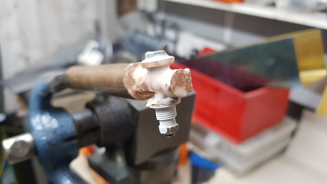 20190223_181212 20190223_181212 by Anne Froud, on Flickr It looks like this after the first heating. 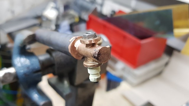 20190223_181646 20190223_181646 by Anne Froud, on Flickr This is the way the Silver Solder is placed. The idea is to make sure that as the Silver Solder melts and droops at the edge, it covers the joint and makes sure it will touch both sides of the joint. 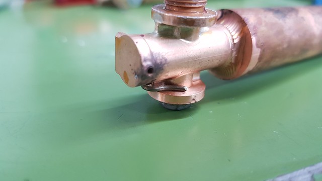 20190223_195722 20190223_195722 by Anne Froud, on Flickr All of it is plastered with flux so keep it clean, even the parts that have already been Silver Soldered. Again, the thread is protected with Tippex. 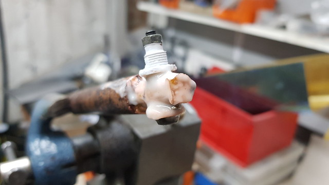 20190223_200202 20190223_200202 by Anne Froud, on Flickr Here's a wobbly video with a bizarre sound track where the noise of the flame presumably was too loud and is clipped. You can see that I'm heating the shaft rather than the end until it's nearly hot enough and the flux is becoming clear all over. After a few seconds of flame on the end, it can be seen to melt and the angle and hotter area or the shank draws the Silver Solder to the rest of the joint. 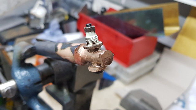 20190223_200701 20190223_200701 by Anne Froud, on Flickr This is how it looks after 20 minutes in the Ultrasonic tank.  20190223_210238 20190223_210238 by Anne Froud, on Flickr It's covered the joints well enough with a nice fillet...  20190223_210250 20190223_210250 by Anne Froud, on Flickr ... and, surprisingly, the Mild Steel rods came out quite easily. I fully expected to have to machine them out, that's why they're soft and not screws. The Side Tank flange fittings still fit nicely. The 4mm hole is going to be opened out to 5mm shortly. 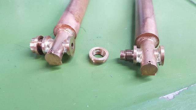 20190223_211922 20190223_211922 by Anne Froud, on Flickr So far, so good. |
|
|
|
Post by 92220 on Feb 24, 2019 8:33:34 GMT
Hi Roger.
They look good!! I boil my silver soldered parts in water to clean the flux off. I've not had much success in the ultrasonic tank. Do you use any special ultrasonic solution or run it at an elevated temperature?
Bob.
|
|
|
|
Post by Roger on Feb 24, 2019 8:58:59 GMT
Hi Roger. They look good!! I boil my silver soldered parts in water to clean the flux off. I've not had much success in the ultrasonic tank. Do you use any special ultrasonic solution or run it at an elevated temperature? Bob. Thanks Bob, I use this from eBay which works pretty well with it heated to 40C in the tank. If you look at the awful video, you can see that I don't like to get things any hotter than absolutely necessary, and for the shortest possible time. The part barely gets noticeably red and then it's done. For most of the heating time, I'm only heating the bar in the vice. This is one reason why I always put the Silver Solder wire in place rather than try to apply it when it's hot. I think the flux comes off so easily because of this. |
|
JonL
Elder Statesman
WWSME (Wiltshire)
Posts: 2,906
|
Post by JonL on Feb 24, 2019 10:27:21 GMT
Fascinating.
|
|
|
|
Post by andyhigham on Feb 24, 2019 10:56:12 GMT
Just one question, Why didn't you machine these as one piece? Material availability?
|
|
|
|
Post by Roger on Feb 24, 2019 11:12:57 GMT
Just one question, Why didn't you machine these as one piece? Material availability? Hi Andy, That's a very good question. Initially I was going to make them like that, and if the valve had two flat flanges I might have done it that way. Having said that, vertical surfaces in 3D machining are troublesome, especially if you have a small radius you need to generate at the bottom. That forces you to use a small ball nosed cutter for finishing, and that has to be a long enough one to reach down the whole face of the flange. It is possible to do this, but it's very time consuming and you're probably going to break quite a few expensive long series cutters. There are no ball nosed PCB cutters. You wouldn't do it that way commercially, you'd use a 5-axis machine so that you could approach the corners from a better angle. That would allow you to use a shorter ball nosed cutter to finish the corner. My decision to use a large thread to attach the valves to the Side Tank, and the extra piece to attach a filter finger made it unviable to machine it from solid. No only would the stock have needed to be really large, it also would make holding it for thread cutting very tricky. It's not the easiest of shapes to hold, hence the decision to keep it on the stock for the machining, Silver Soldering, and subsequent machining, including boring the hole for the valve barrel. That's why I took the trouble to clock up the stock to get the body lined up with the bore. It's much easier to realign the part precisely to the CAM datum if it's truly in the middle of the stock. Hopefully that makes sense. |
|


