uuu
Elder Statesman
 your message here...
Posts: 2,808
|
Post by uuu on Mar 31, 2019 15:49:56 GMT
Cunning plan, to prevent an easily removable and cleanable item getting blocked by fitting an inaccessible filter, to get blocked instead. If all else fails, you can poke them through with a rod.
Wilf
|
|
|
|
Post by Roger on Mar 31, 2019 16:05:12 GMT
Cunning plan, to prevent an easily removable and cleanable item getting blocked by fitting an inaccessible filter, to get blocked instead. If all else fails, you can poke them through with a rod. Wilf Hi Wilf, I think it highly unlikely that the filter will get blocked, it's only passing water that's already been filtered. If after many years of use it needs flushing, then that's what I'll do. It's not something I'm going to lose any sleep over! |
|
pault
Elder Statesman
Posts: 1,496
|
Post by pault on Mar 31, 2019 16:39:33 GMT
Ref cleaning filters and tanks, stick a hose in the tank and turn the water on so the tank is overflowing. Blow water (ideal) or steam/air wrong road through the filter back into the tank. If using steam or air keep stopping and allow water to fill the filtets/pipes then repeat.
The idea is for the water to flow through the filters the wrong way carrying any foreign objects into the tank. The water overflowing (The more the better) carries the rubbish away.
This idea will also clear blockages which can stop injectors working. Block the injector overflow, turn on the steam, open the water valve. Wait until you hear the steam rattling in the water tank. Turn the steam off let the water cool the injector/plumbing, turn the injector on as normal
|
|
dscott
Elder Statesman
Posts: 2,438
|
Post by dscott on Apr 1, 2019 5:35:18 GMT
CONGRATULATIONS ROGER 10,000 posts you will be getting your silver button... Sorry that is You Tube he jokes!
Do we need another level or more stars when we achieve this status?
Get her a pair of tights or stockings... 1501 I mean held in place within the filler cap when running and withdrawn
when finished!
David, and Lily who being brown does not seem to have any tights!!
|
|
|
|
Post by Roger on Apr 2, 2019 22:00:59 GMT
Trying to get the Pannier tank folds exactly right and the tops parallel isn't easy so I've made a couple of letterbox gauges to slip over the tanks to check they're right when the inner wrapper is installed. 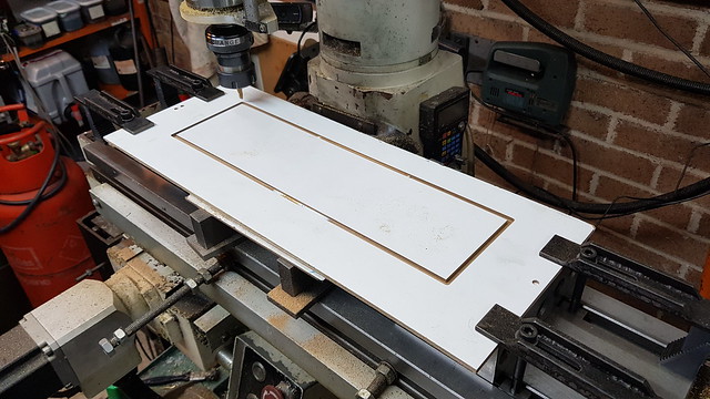 20190401_220252 20190401_220252 by Anne Froud, on Flickr 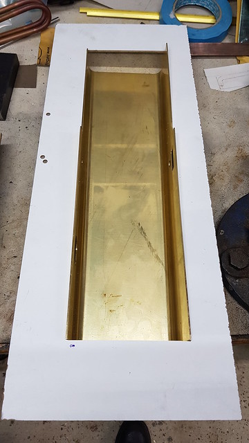 20190402_160946 20190402_160946 by Anne Froud, on Flickr The inner wrapper has had the bottom edge fold moved near the front of the tank because the radius was a little too tight. Here it's set up for drilling the rivet holes that hold the inner wrapper in place. The front plate was rested in place to set the correct position. 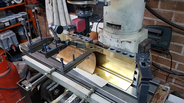 20190402_212223 20190402_212223 by Anne Froud, on Flickr I drilled holes near the end first and put rivets in there in case it moved.  20190402_214727 20190402_214727 by Anne Froud, on Flickr The edge of the wrapper was clocked true so they are neatly in line along the edge. 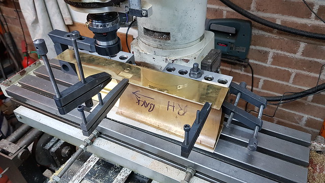 20190402_224816 20190402_224816 by Anne Froud, on Flickr |
|
JonL
Elder Statesman
WWSME (Wiltshire)
Posts: 2,907
|
Post by JonL on Apr 3, 2019 21:02:12 GMT
You are really dedicated to accuracy, thats very admirable. The results will be fantastic.
|
|
|
|
Post by Roger on Apr 3, 2019 22:42:59 GMT
You are really dedicated to accuracy, thats very admirable. The results will be fantastic. To be honest, it doesn't really take any longer to do it that way. Marking it out by hand, using a centre punch then centre drilling, lining it up by eye then drilling each one is not a five minute job. You still need to have an angle plate or something to keep it upright. A few minutes to clamp it and clock one edge then another couple to find the corner with the wobbler is all it takes to then put them in to coordinates. It's a fairly rigid setup so the 1.6mm carbide drill goes straight in without a centre drill. I wouldn't want to use a Carbide drill like that by hand. Total time about half an hour taking it slowly with a bit of care. I find it's just as easy to do these jobs where accuracy isn't that important in the same way as I would if they were. Then there are no mishaps and holes going awry trying to take short cuts and get the job done quickly. I know they will all get filed off and won't be seen, but I find it pleasing to see them nicely spaced and in a straight line. |
|
|
|
Post by 92220 on Apr 4, 2019 7:50:15 GMT
Hi Roger.
As Nobby says, it's going to be one fantastic model. As far as lining up goes, I never bother clocking an edge on the mill. One of my 1/2" thick parallels is a push fit in the mill table tee-slots so I just push that in and set parts against it as I clamp. I can't remember the last time I actually clocked an edge of a part on the mill. I must admit that only one of the set of parallels fits the slots though.
Even if I want to line up at 90 degrees, I fit the parallel and then use a square against it, and if necessary clamp another parallel across the bed while trued up with the square. Mind you, when I use a square I always use one of my Eclipse squares which has been checked at dead square. I have a set of Clarke engineers squares and none of them are exactly square, so don't get used these days.
On a different note, I totally agree with your earlier comments about the use of PCB drills. Since you introduced me to them I have made up quite a collection of different, useful, sizes and use them a lot. For starting deeper holes, I often use a 0.8mm in preference to a small centre drill now. I've also gravitated from HSS to carbide milling cutters for most milling now too.....at least for sizes under 3/8" (10mm).
Bob.
|
|
|
|
Post by Roger on Apr 4, 2019 8:41:13 GMT
Hi Roger. As Nobby says, it's going to be one fantastic model. As far as lining up goes, I never bother clocking an edge on the mill. One of my 1/2" thick parallels is a push fit in the mill table tee-slots so I just push that in and set parts against it as I clamp. I can't remember the last time I actually clocked an edge of a part on the mill. I must admit that only one of the set of parallels fits the slots though. Even if I want to line up at 90 degrees, I fit the parallel and then use a square against it, and if necessary clamp another parallel across the bed while trued up with the square. Mind you, when I use a square I always use one of my Eclipse squares which has been checked at dead square. I have a set of Clarke engineers squares and none of them are exactly square, so don't get used these days. On a different note, I totally agree with your earlier comments about the use of PCB drills. Since you introduced me to them I have made up quite a collection of different, useful, sizes and use them a lot. For starting deeper holes, I often use a 0.8mm in preference to a small centre drill now. I've also gravitated from HSS to carbide milling cutters for most milling now too.....at least for sizes under 3/8" (10mm). Bob. Hi Bob, Agreed, lining up with the tee slots like that is quick and good enough for many jobs. I have a series of programs to move back and forth over different distances so that clocking takes barely a minute from start to finish. My philosophy tends towards rapid setups using the most accurate methods, even if they aren't always necessary. I'll always clock up the vice if it's not in the orientation that uses the dowels. It's easy to set it quickly using a less accurate method and they forget and use it for something that requires better accuracy. For the sake of a minute, I just clock everything then I know it's as good as it get. It's overkill, but I've never looked back and wished I'd done something less accurately, whereas I can't say the same for the opposite. Squares are good, but it's still easy to be a thou out on a vice jaw end to end if everything isn't squeeky clean. |
|
|
|
Post by Roger on Apr 5, 2019 20:49:37 GMT
This is the second pannier tank inner wrapper being adjusted. The curve was slightly too tight a radius so I needed to move the fold and trim the edge back. I normalised the Brass again to make sure it was soft enough to take the abuse without cracking. Here it's having a triangular piece trimmed off the edge.  20190404_112526 20190404_112526 by Anne Froud, on Flickr Then it was on to attaching it to the outer wrapper...  20190405_171001 20190405_171001 by Anne Froud, on Flickr ... and adjusting the divider plate to fit when it's all right to the template.  20190405_173547 20190405_173547 by Anne Froud, on Flickr The front plate is going to be held on with Copper rivets lightly formed into shallow countersinks and then Soft Soldered. The inner wrapper is probably going to be attached with rivets but using 3mm square Brass instead of angle because it's more compact and will fit on the accessible side.  20190405_214037 20190405_214037 by Anne Froud, on Flickr |
|
|
|
Post by Roger on Apr 6, 2019 21:22:08 GMT
Lots of boring stuff today I'm afraid, spotting through existing holes into the angles behind them such as here...  20190406_103529 20190406_103529 by Anne Froud, on Flickr ... so the end plates look like this.  20190406_154348 20190406_154348 by Anne Froud, on Flickr I've got a lot of holes to drill in the wrapper, and they're all referenced to a convenient flat surface, so it's worth spending a few minutes setting up the 2x4x6 blocks so they're both parallel to the X-axis of the mill. Here I've clamped a long parallel between the two so they're aligned and then I'm clocking the parallel to get them both straight.  20190406_191031 20190406_191031 by Anne Froud, on Flickr So first up is the bottom of the LH tank at the front. I'm pushing the front plate inwards and towards the back with the two clamps in the foreground to make sure it stays where I want it.  20190406_191802 20190406_191802 by Anne Froud, on Flickr I've also used an additional Toolmaker's clamp to make double sure it doesn't move.  20190406_194012 20190406_194012 by Anne Froud, on Flickr A similar arrangement works on the top of the same tank with it flipped over.  20190406_202147 20190406_202147 by Anne Froud, on Flickr Once both tanks were done, the setup was changed to this arrangement to drill the holes in the side of the tank for the front angles.  20190406_213610 20190406_213610 by Anne Froud, on Flickr On all of these, I've used the wobbler to set the right distance from the end and then used a 1.6mm PCB drill to go straight through the pair without the need for a centre drill.  20190406_213622 20190406_213622 by Anne Froud, on Flickr Not much to show for a lot of hours work, but it does all look like it's in the right place so it was worth taking a bit of time to get it right. There's still the inner wrapper to fix to the end, but that's going to have to wait for the 3mm square Brass before I can get on with that. 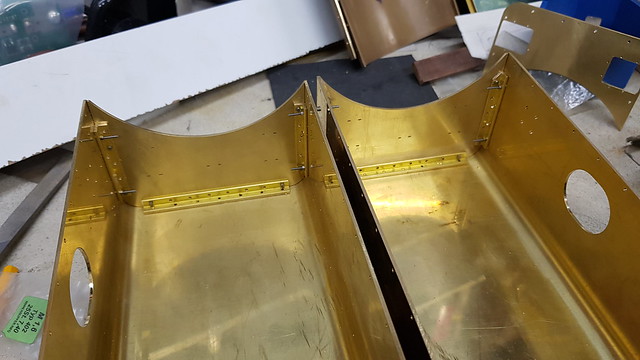 20190406_221135 20190406_221135 by Anne Froud, on Flickr |
|
jma1009
Elder Statesman
Posts: 5,901
|
Post by jma1009 on Apr 6, 2019 22:08:35 GMT
Hi Roger,
Soft solder for tanks IMHO requires a lot of angle section brass to get a good joint, and I would make up curved bits of angle to fit the gaps in your above pic. I would also ensure every otherwise plain butt joint had angle added, apart from your structural midway section with it's cut outs which doesn't matter I assume.
A plain butt joint in soft solder without angle added is asking for trouble in my book. All sorts of lap joints in the angle are also required.
If you want any large lumps of old fashioned plumbers lead solder let me know - I've got far too much and will never use it all up on the one particular miniature loco I intend to build.
Cheers,
Julian
|
|
|
|
Post by Roger on Apr 6, 2019 22:39:50 GMT
Hi Roger, Soft solder for tanks IMHO requires a lot of angle section brass to get a good joint, and I would make up curved bits of angle to fit the gaps in your above pic. I would also ensure every otherwise plain butt joint had angle added, apart from your structural midway section with it's cut outs which doesn't matter I assume. A plain butt joint in soft solder without angle added is asking for trouble in my book. All sorts of lap joints in the angle are also required. If you want any large lumps of old fashioned plumbers lead solder let me know - I've got far too much and will never use it all up on the one particular miniature loco I intend to build. Cheers, Julian Hi Julian, The front plate has a rebait around the edge of it, it's not a butt joint, so I'm not sure if it will need the corners filled in or not? I do have some 3mm square brass coming though, so that could be bent to fit the corners if necessary. It is a matter of strength that's the issue with butt joints, or just getting it water tight? The tanks are made from 1.5mm thick Brass, so they're pretty stiff especially when the curved inner wrapper is attached. Another option would be to machine some angle quadrants from round Brass bar since I have rather a lot of that kicking around. Thanks for you kind offer of the Plumbers solder, I think I've got two chunky rolls in the drawer which might be enough though. I'll have to check. |
|
|
|
Post by Roger on Apr 7, 2019 11:18:58 GMT
This is a piece of Brass being turned into four corner segments of angle...  20190407_105406 20190407_105406 by Anne Froud, on Flickr ... there's 3mm between each segment so they can be cut and still have enough material to fit to the corners I've already added the straight angles to...  20190407_110302 20190407_110302 by Anne Froud, on Flickr ... like this. I'm going to make the corners with machined ends for the rear of the tank and add those first since it's easier to fit straight angles between them than the other way round. I'll spot the rivet hole through. I don't think it's necessary to rivet the outside radius.  20190407_121142 20190407_121142 by Anne Froud, on Flickr |
|
|
|
Post by delaplume on Apr 7, 2019 16:02:39 GMT
Hi Roger,
Quote}--- "I'm going to make the corners ----------------- and add those first since it's easier to fit straight angles between them than the other way round"
Just like doing coveings on the wall / ceiling interface at home...or lining-out etc..
Looking good, young chap !!
|
|
|
|
Post by ettingtonliam on Apr 7, 2019 17:17:50 GMT
Just like technical drawing too, as it was taught to me - draw circle first, then draw tangent lines to the circle, not the other way around.
|
|
|
|
Post by Roger on Apr 7, 2019 19:55:36 GMT
I have a general question about the Soft Soldering of tank assemblies. Mine is going to be held together with Copper rivets so it's already mechanically strong before Soft Soldering. The idea is not to put any mechanical forces on the Soft Soldered joints.
Obviously it all needs to be really clean before going together, I won't be fluxing anything ahead of time since I know how quickly that corrodes if you don't get on with Soldering shortly afterwards.
I'm thinking of Soldering the angles to the end plates and adding the footsteps and handrails in a couple of operations and then attach those to the wrapper in a separate operation. I know the solder will re-melt, but it would give the opportunity to clean and inspect/rework any joints that look suspect before moving on.
I have a monster soldering iron, but I'm not sure if that's an appropriate way to heat the parts. I'm thinking I'll probably be better off with a blow torch unless I specifically want to heat one small area. I think it's likely to be more messy using an iron.
I also plan to use Tippex to contain the Solder since it's likely to want to run everywhere.
If anyone would like to share their experiences, I'd be interested to hear what you did and the problems you faced.
|
|
uuu
Elder Statesman
your message here...
Posts: 2,808
|
Post by uuu on Apr 7, 2019 20:05:07 GMT
It's decades since I did any soft soldering, but I was always in favour of tinning the joint surfaces before assembly. Then the heat up afterwards just fused it all together.
Wilf
PS and I used a big iron, heated with a blowlamp, or on a gas ring.
|
|
jma1009
Elder Statesman
Posts: 5,901
|
Post by jma1009 on Apr 7, 2019 20:23:20 GMT
You don't need to tin faces as suggested by Wilf.
Bakers Fluid will clean everything up as it gets hot for the soft solder, and the soft solder will then flash around. Stepney's side tanks were heated up gently with a waving diffuse propane flame.
Years ago I heated this sort of thing up in the domestic oven, then after removing from the oven added the Bakers Fluid flushed about using asbestos gloves then added large sticks of old fashioned plumbers solder adding the propane torch gently and from a distance. An ordinary small paint brush soaked in Bakers Fluid moves stuff around if it is being awkward.
An old no longer wanted electric domestic iron can also be of use clamped upside down in the vice.
I am not very good at soft soldering.
Bakers Fluid is quite corrosive and if you use it Roger you will need to have your garage door open and prevent it dripping onto anything of value or importance. But it is very effective with old fashioned lead solder, and also Jim Scott's Arax 96 (which I can highly recommend and is well worth using as I did all the awkward joints on Stepney's side tanks with it where extra strength is required).
Cheers,
Julian
|
|
don9f
Statesman
 Les Warnett 9F, Martin Evans “Jinty”, a part built “Austin 7” and now a part built Springbok B1.
Posts: 960 
|
Post by don9f on Apr 7, 2019 20:37:19 GMT
I’m just in the process of making the bunker for the Jinty 3F....it contains a water tank in the lower section. Along with the side tanks made some years ago it is brass plate with brass angle type construction. 1\16” copper rivets and 8BA brass csk. screws hold it all together. The joints are clean when assembled and when ready for soldering, are brushed with Bakers Fluid. I just use a small propane torch to heat things carefully and apply ordinary cored 60/40 soft solder, generally from the inside. It flows well and yes, some goes where it’s not needed but inside that’s not really a problem to me. If any blobs need to be scraped off, I use an old but sharp 1/2” wood chisel.
Like you say, joints already done do melt a bit when adding further bits on but this hasn’t been a problem so far. When I built the 9F tender even more years ago, I did it exactly the same way and never had any leaks.
A friend of mine at our miniature railway was telling me only the other day that he bought a 300W electric iron (from Korea!) to solder the tank on a Hunslet loco he is building and it did the job very well....same sort of construction.
Hope this is of interest but it’s likely that both methods work well if done correctly!
Cheers Don
|
|


