|
|
Post by 92220 on Nov 16, 2019 9:40:57 GMT
Hi Roger, Maybe a bit of an off side but a couple of weeks ago I was in the same boat, except the part had NO DIMENSIONS! A call to my son via Viber in Canada for some questioning on what to do. Easy, well for him any way, import the drawing, mine a re PDF, straight into CAD, you then find yourself a nice clear dimension, select the whole of the drawing this bit is important top right to bottom left, he did explain why but I’m not sure now, you then type SC, for scale & follow the instruction. Done! Then just draw a line or arc ( use the 3 point option) check the properties & see how close you are. If not the tweak the scale on the drawing properties. Worked great for me, the drawings are 1908 & when you zoom in they tend to get a bit fuzzy, so a little fluffy it about on start end of the line can help. You probably know all this but just incase. Now for the really weird bit, as I was doing this via Viber & can do video at the same time I had my phone viewing the screen so he could watch & talk me thru it. With the drawing zoomed I happen to notice that the picture on the phone was nice & clear! No fuzzy lines. I have since tried with the magnifying app & it’s no we’re near as clear. Hope some of this rambling is of use. Cheers Kerrin Hi Kerrin. That's more or less how I did it, but I always look for the largest drawn dimension on the drawing and scale the whole until the drawn dimension comes down to the scale dimension needed. By using the largest drawn dimension, it minimises scaling error. Also, arcs/fillets may not be accurate, but all lines drawn at right angles, or at least with a draughting machine, should be pretty accurate, so can be used for scaling purposes. Bob. |
|
|
|
Post by 92220 on Nov 16, 2019 9:43:56 GMT
The problem with the single distance used to scale a drawing is that a paper drawing is often stretched along its length by a different factor than its width, often caused by the copy method. If this is the case make the image a block and then insert with independant x and y scales to correct in both directions and then explode it to bring it back to a simple image. Used this many times to correct plans for town planning when I was in that field. Hi Pete. Yes that is necessary to get scaled dimensions correct, or at least nearly so. I forgot to mention that! Thanks fdor the reminder. It is an important factility to getting things right. Bob. |
|
|
|
Post by Roger on Nov 16, 2019 11:20:24 GMT
I have the Works Drawing 91470 bearing the title 'GWR Standard Whistles and Gear' which shows absolutely everything about the whistles, brackets, valves, fitting, chains and erection details. However, the standard arrangement doesn't appear to include the deflector on the back of the whistle pictured below. Does anyone have a drawing or dimensions of that item?  IMG_1415 IMG_1415 by Roger Froud, on Flickr |
|
dscott
Elder Statesman

Posts: 2,437
|
Post by dscott on Nov 17, 2019 0:16:52 GMT
On Pondering Swindon's love of using things more than once say a bash over the standard shovel...
BUT it has a very slight fold just above the whistles.
Can I put in for at least 8 of them if you make a press tool Please?
The one on the Prairie 4121 is about the size of my thumb and is slimmer. She lives in the Garage.
While the one on the Dapol 5700 Panner tank is a work of art with the bottom bracket bent to the rear. On my Coalmine model in progress.
They have made it straight.
David and Lily. In anticipation of the next Chapter.
|
|
|
|
Post by Roger on Nov 17, 2019 8:29:21 GMT
On Pondering Swindon's love of using things more than once say a bash over the standard shovel... BUT it has a very slight fold just above the whistles. Can I put in for at least 8 of them if you make a press tool Please? The one on the Prairie 4121 is about the size of my thumb and is slimmer. She lives in the Garage. While the one on the Dapol 5700 Panner tank is a work of art with the bottom bracket bent to the rear. On my Coalmine model in progress. They have made it straight. David and Lily. In anticipation of the next Chapter. Hi David, It's certainly not going to be very big. I do have it shown on the GA, so if push comes to shove I'll have to scale some it off that. It looks like it might not be a standard item although the way it's attached and the form of the lower part appears to be common. 1501 has a rod between the top of it and the cab, presumably to steady it. If you look at the GA, the deflector shown is shorter than that actually fitted to 1501. Presumaly they originally detailed one from an existing locomotive but realised either before or after it was built that it wasn't satisfactory. It might be due to the style of the opening in the top of the cab allowing steam to enter if the deflector doesn't go right to the top. Presumably the drawing for this has long since been lost. Another clear difference between the GA and 1501 is how it's mounted on the boiler. The GA would have you believe that it's attached to a block that's attached directly to the boiler shell. Presumably there would have been a cutout in the claddind to allow that through. Alternatively, it's just a cockup on the drawing and it should have been shown as being attached to the cladding, although that wouldn't have been very strong.  Whistle on the GA Whistle on the GA by Timothy Froud, on Flickr It's hard to see on this photo whether there's a cutout in the cladding around the mounting block or whether that's just a shadow.  IMG_1415 IMG_1415 by Timothy Froud, on Flickr |
|
|
|
Post by doubletop on Nov 17, 2019 8:41:53 GMT
Roger
Just emailed you the pages from ME4499 of the John Smith drawings for the 14xx.
Pete
|
|
|
|
Post by ettingtonliam on Nov 17, 2019 9:09:38 GMT
It certainly looks like a circular cut out in the cladding below the shield, and I can't think what would show a circular shadow just there. I've got a photo of 1504 in BR days, and the top of the shield is quite a bit above the cab roof. In your photo of 1501 the edges of the shield seem to rise vertically before tapering back to the top - nothing like the drawing!
|
|
|
|
Post by 92220 on Nov 17, 2019 10:35:06 GMT
Hi Roger. I've taken the photo and blown it up around the base of the whistle. It looks like 2 rusty holes on the cladding. Here is the blow-up:- 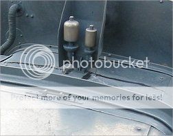 You have lots of reference points in the photo. With the drawings you have, could you not reconstruct a drawing of the whistle guard? Bob. |
|
|
|
Post by 92220 on Nov 17, 2019 10:37:31 GMT
Hi Roger.
I expected the photo to be enlarged on here but it isn't. I will email you the blown up section.
Bob.
|
|
|
|
Post by Roger on Nov 17, 2019 12:03:52 GMT
Hi Roger. I've taken the photo and blown it up around the base of the whistle. It looks like 2 rusty holes on the cladding. Here is the blow-up:- You have lots of reference points in the photo. With the drawings you have, could you not reconstruct a drawing of the whistle guard? Bob. Thanks for that Bob, it looks like you're right about that. I'll have to see how I can make it appear like that. |
|
|
|
Post by Roger on Nov 17, 2019 12:04:36 GMT
Hi Roger. I've taken the photo and blown it up around the base of the whistle. It looks like 2 rusty holes on the cladding. Here is the blow-up:- You have lots of reference points in the photo. With the drawings you have, could you not reconstruct a drawing of the whistle guard? Bob. Thanks for that Bob, it looks like you're right about that. I'll have to see how I can make it appear like that. Yes, I'm sure I can do that. As you say, there's a lot of information available there. |
|
baldric
E-xcellent poster

Posts: 208
|
Post by baldric on Nov 17, 2019 13:38:51 GMT
The whistles are attached to the bracket that in turn attached to the boiler, not the cladding, at least on all other GWR engines that I am aware of with the whistles on the boiler.
You mention a support from the cab, I assume that is on a different drawing rather than the one posted as that shows only the steam feeds.
Baldric.
|
|
baldric
E-xcellent poster
Posts: 208
|
Post by baldric on Nov 17, 2019 13:40:17 GMT
Doh, I now see the bolt presumably for the support on the photos....
Baldric
|
|
|
|
Post by sniffipn on Nov 18, 2019 19:22:09 GMT
additive manufcture for a fixture - brilliant roger. seen it suggested in a markforged webinar. not seen model engineers use the principle. www.youtube.com/watch?v=rcg5p9O6PQAinspirational yet again roger |
|
bri
Member

Posts: 6
|
Post by bri on Nov 18, 2019 19:49:51 GMT
Hi Roger,
the whistle bracket was originally mounted on a boss that was welding to the top of the firebox - as per the GA. This required a hole to be cut into the cladding sheet for the bracket to pass through. During restoration, the cladding sheet was replaced without the hole for access to this boss. The hole in the cladding allowed water dripping from the whistles to pass directly inside the cladding and onto the top of the firebox with risk of increased rate of corrosion. The whistle bracket is now bolted directly to the top face of the firebox top cladding plate.
The shape of the whistle shield currently on 1501 was estimated / designed based on photos of 15xx's in service, which always seemed to be much larger than that shown on the GA. Sorry, I don't have any drawings of the current shield. A piece of 1/2 dia bar steadies the top of the whistle shield to the cab front.
Hope that helps
Brian.
|
|
|
|
Post by Roger on Nov 18, 2019 20:14:49 GMT
additive manufcture for a fixture - brilliant roger. seen it suggested in a markforged webinar. not seen model engineers use the principle. www.youtube.com/watch?v=rcg5p9O6PQAinspirational yet again roger Thanks for the link, that's an intersting use of 3D printing. I'm glad you liked my twist on that theme. Simple enough really, but a game changer. |
|
|
|
Post by Roger on Nov 18, 2019 20:24:09 GMT
Hi Roger, the whistle bracket was originally mounted on a boss that was welding to the top of the firebox - as per the GA. This required a hole to be cut into the cladding sheet for the bracket to pass through. During restoration, the cladding sheet was replaced without the hole for access to this boss. The hole in the cladding allowed water dripping from the whistles to pass directly inside the cladding and onto the top of the firebox with risk of increased rate of corrosion. The whistle bracket is now bolted directly to the top face of the firebox top cladding plate. The shape of the whistle shield currently on 1501 was estimated / designed based on photos of 15xx's in service, which always seemed to be much larger than that shown on the GA. Sorry, I don't have any drawings of the current shield. A piece of 1/2 dia bar steadies the top of the whistle shield to the cab front. Hope that helps Brian. Hi Brian, Many thanks for that explanation, it explains at least part of the story. I've got one very clear side view of 1500 in which the whistle shield is considerably higher than the top of the cab. A similar arrangement appears to be on 1501 on an early photo although it's pretty blurred. I've also got one of 1501 when it arrived for restoration, and it's clearly lower than the top of the cab. I guess these things are not set in stone, they evolve as the locomotive goes through its life. Anyway, thanks for clearing up the conundrum of the mounting of the whistle, I'll probably just bolt it to the cladding. |
|
|
|
Post by Roger on Nov 18, 2019 20:31:53 GMT
This is my interpretation of what's on 1501 now. It's hard to know how close it is because the perspective is taken from a different point.  Whistle on boiler front view Whistle on boiler front view by Timothy Froud, on Flickr The side view is even more difficult to line up for the same reason. However, modelling it with a constant 10 degree angle for the sides results in the slight bend that you can see on the side on mine about half way up. You can't really make that out on the photo, but on the original you can see that same artifact on the side too. This convinces me that I've constructed it in much the same way as the real thing.  Whistle on boiler side view Whistle on boiler side view by Timothy Froud, on Flickr It's a pain in the neck to make from sheet because it can't be folded. It has to be made from at least three pieces. I think I'll probably just machine it from Solid since it's not very big. |
|
|
|
Post by ettingtonliam on Nov 18, 2019 20:51:56 GMT
Isn't it even worse than that Roger, because according to the GA, the back has a very short vertical section at the bottom where the whistles themselves pass through it? You can't see it in that last photo of yours because the edge of the firebox cladding gets in the sight line.
|
|
|
|
Post by Roger on Nov 18, 2019 21:52:33 GMT
Isn't it even worse than that Roger, because according to the GA, the back has a very short vertical section at the bottom where the whistles themselves pass through it? You can't see it in that last photo of yours because the edge of the firebox cladding gets in the sight line. Indeed, it's all a matter of guesswork and massaging things to make it look plausible. I think the perspective view is always taken from a distance, so even when you zoom in, you're not getting the same view that you would from a camera that's close to the subject. It's bound to be wrong, not just because of that, but also because the height of the boiler is sure to be slightly different to the real thing. Such is life, it's just going to have to be my best effort and hope nobody notices it's miles out! |
|


