|
|
Post by 92220 on Jan 17, 2020 10:04:50 GMT
Hi John.
Sorry. I didn't know it was your original design, with mods by Roger. Between you, you have produced a really simple, easily made, easily used, bender that is capable of bending almost any cross-section, provided the forming rolls are made. Brilliant!!!
Bob.
|
|
|
|
Post by Roger on Jan 18, 2020 10:19:52 GMT
Just a quick 'heads up', there's a new listing on eBay for different sizes of Fluorosint if anyone is looking to make Piston rings from it. |
|
|
|
Post by Deleted on Jan 18, 2020 14:24:44 GMT
Thanks for the heads up Roger...for a minute I thought you may have found a cheaper supplier as I desperately need a cheap supply...alas, these are much dearer for the size I need compared with the other suppliers out there... keep looking though...you never know it may come down in price one day...  Pete |
|
|
|
Post by Roger on Jan 18, 2020 15:11:53 GMT
Thanks for the heads up Roger...for a minute I thought you may have found a cheaper supplier as I desperately need a cheap supply...alas, these are much dearer for the size I need compared with the other suppliers out there... keep looking though...you never know it may come down in price one day... Pete Hi Pete, You won't find it cheap unless someone has no idea of the value of it. That's what happened with the lot I bought, but it's not big enough for the piston rings unfortunately. |
|
|
|
Post by Deleted on Jan 18, 2020 15:19:27 GMT
Well I need 3/4 for my valves and on that link you gave 1 " costs £14... the same from M-machine is £10.80... not sure if that includes VAT or not but still much cheaper... 6" worth is still too much for me just now, I could get away with less but I may want to experiment with design plus need enough to hold it securely in the chuck...
|
|
|
|
Post by Roger on Jan 18, 2020 19:12:46 GMT
Well I need 3/4 for my valves and on that link you gave 1 " costs £14... the same from M-machine is £10.80... not sure if that includes VAT or not but still much cheaper... 6" worth is still too much for me just now, I could get away with less but I may want to experiment with design plus need enough to hold it securely in the chuck... I've just noticed that the supplier is m-machine on eBay. |
|
|
|
Post by Deleted on Jan 18, 2020 20:32:33 GMT
Really?.... strange, I hadn't noticed that either?
|
|
|
|
Post by Roger on Jan 21, 2020 22:49:19 GMT
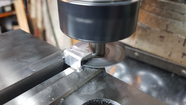
This is the final piece of edging going onto the bunker.  20200118_143540 20200118_143540 by The train Man, on Flickr I had to use a Carbide drill for spotting through because the 'HSS' drills I bought were garbage and wouldn't cut Steel at all.  20200118_181955 20200118_181955 by The train Man, on Flickr Anyway, that completes the edging. The joining plates still need to be riveted onto the bottom half and filed flat. On the real thing the plates are welded. 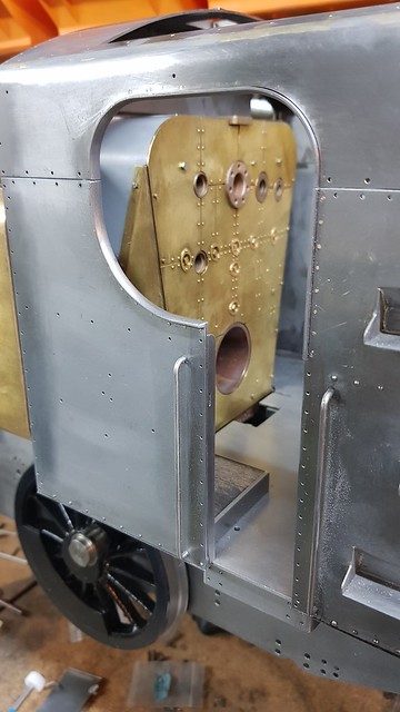 20200118_202631 20200118_202631 by The train Man, on Flickr The shelf and front of the bunker is removable to make firing easier. I've been told it's perfectly possible to fire with the shelf in place, and I might end up running like that. However, I prefer to have the option to be able to see deep into the firebox, something you definitely can't do with the shelf in place. I'm still not 100% sure as to how this will be held in place yet, I want to make the shelf first and see how it fits. I might just use magnets, or I may have something more positive. We'll see.  Bunker removable shelf Bunker removable shelf by The train Man, on Flickr Anyway, the edge of the removable shelf has the same corner detail as this fixed part, ie I've machined it so it looks like the plate is much thinner than it actually is.  Closeup bunker shelf cutout Closeup bunker shelf cutout by The train Man, on Flickr The cutout was machined like this, with the edge set vertically in the vise.  20200120_195309 20200120_195309 by The train Man, on Flickr I'll need some angles for the inside to join the front to the shelf, and another one across the back at the top to engage with the rear of the cab which has the windows in it.  20200121_115322 20200121_115322 by The train Man, on Flickr I'm using the same generic model for the Vee groove and profile. All I have to do is to change the length and output the two programs and the CAM outputs the required G-code  20200121_173105 20200121_173105 by The train Man, on Flickr So it's the same method again, just carefully fold along the Vee groove, clean with Meths then flux and heat up. I've used a few short pieces of Silver Solder, it doesn't need a huge amount.  20200121_212830 20200121_212830 by The train Man, on Flickr Again, I run a pointy piece of Titanium welding wire along the molten joint to make sure it's even.  20200121_212953 20200121_212953 by The train Man, on Flickr |
|
|
|
Post by Roger on Jan 22, 2020 20:55:54 GMT
Houston, we have a problem... Hmmm, now the 3D model shows the valve shaft in line with the valve, so something is amiss here. Thats's about 1mm out! It turns out that I've played fast and loose with the dimensions of the valve flange, forgeting that the face to centre line distance is important.  20200122_093858 20200122_093858 by The train Man, on Flickr Holding it is a bit of a challenge, because I need to keep taking it on and off the lathe to shave the face to length. I'm going to take off exactly one turn which is 0.75mm Ok, that's probably not quite enough, but I can shim a small error. The hole isn't perfectly central to the hole, so I've got to set this up in a specific orentation and be able to put it back that way. The solution I've opted for is to use the slot where the gauze finger was going to be as a stop. I've cross drilled a piece of 5mm Silver Steel and put a 3mm dowel across the centre. The valve is held on by an M3 bolt and a spacer plus washer. It's a bit clumsy, but it will do.  20200122_180016 20200122_180016 by The train Man, on Flickr  20200122_180423 20200122_180423 by The train Man, on Flickr The first one was adjusted fine, but the second one went round just a shade too far. Here I've protected the thread with Tippex and then used some Lead Free high temperature Soft Solder to build up the face. This is what I've done on the other fittings. It's ideal because you can do it any number of times. The Tippex was removed with Acetone and a wire brush.  20200122_202747 20200122_202747 by The train Man, on Flickr Then is was back onto the Lathe for trimming to length. 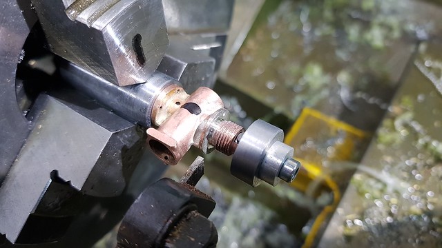 20200122_203508 20200122_203508 by The train Man, on Flickr Now that's more like it! In the process I've managed to damage the two valve elements which were too tight really. I'll make those again with a looser fit.  20200122_204109 20200122_204109 by The train Man, on Flickr It's a bit fustrating to have to go back over these things, but I won't be happy unless it's right. |
|
jma1009
Elder Statesman

Posts: 5,900
|
Post by jma1009 on Jan 22, 2020 22:36:44 GMT
Hi Roger,
That must have been annoying - we all have these issues from time to time.
Cheers,
Julian
|
|
peteh
Statesman
 Still making mistakes!
Posts: 760
|
Post by peteh on Jan 23, 2020 0:10:49 GMT
Nicely recovered Roger |
|
|
|
Post by Roger on Jan 23, 2020 22:16:20 GMT
Time to remake the valve elements from Flurosint, this time with a looser fit. I'm using a 1mm cutter to finish the internal hex...  20200123_112820 20200123_112820 by The train Man, on Flickr ... then a 4mm cutter to machine the through hole before creating the rear clearance and parting off.  20200123_111343 20200123_111343 by The train Man, on Flickr As usual, I've taken the opportunity to improve the design. The original valve element had a long body, and that meant that it was very difficult to get it out. Removing the valve requires using a small piece of Silver Steel or a small Allen key to push the valve towards the gland end. You can reach through where the water goes to do that. Once the end is showing, compressed air can get behind it and pop it out. However, the old design had to move rather a long way before the end of the valve was far enough to do that. The new design doesn't have to come out as far, so it's much easier to then pop it out with compressed air. Hopefully that makes sense! 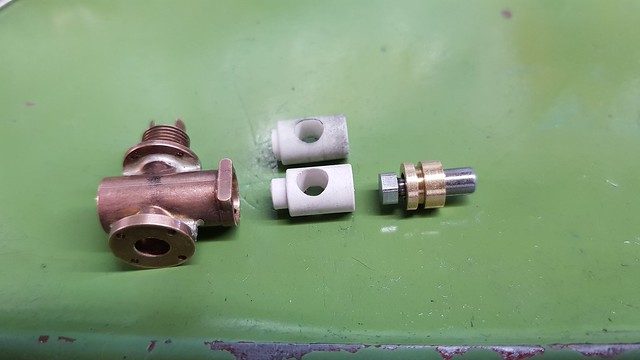 20200123_113657 20200123_113657 by The train Man, on Flickr Anyway, moving on to the handles that are in the cab, I need three of those. This is a piece of 6mm Silver Steel which will become the body of the handle.  20200123_215938 20200123_215938 by The train Man, on Flickr The hole in the side was originally 1.7mm but I've opened it out to 2mm because it seemed a bit flimsy.  20200123_162813 20200123_162813 by The train Man, on Flickr The joint to the handle is pretty small, even with a few adjustments away from scale sizes. To make it as strong as possible, I'm using Silicon Bronze for the joint. I've only got 1.6mm diameter wire, so I've progressively turned this piece about 1mm at a time down to 0.8mm  20200123_172655 20200123_172655 by The train Man, on Flickr This is the first one I scrapped in the end. The setup was a bit of a lash up really. 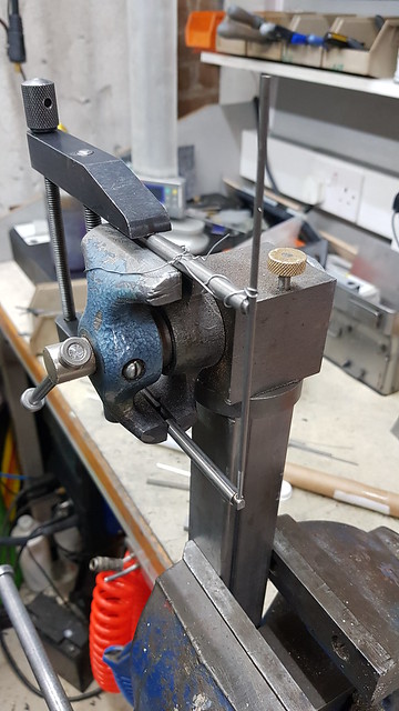 20200123_175622 20200123_175622 by The train Man, on Flickr  20200123_180116 20200123_180116 by The train Man, on Flickr This is a better setup for the second one. The Silicone Bronze wire is bent into a horseshoe around the base of the handle. The handle is just a piece of 2.4mm diameter Silver Steel ground to a taper on the Tool & Cutter grinder. 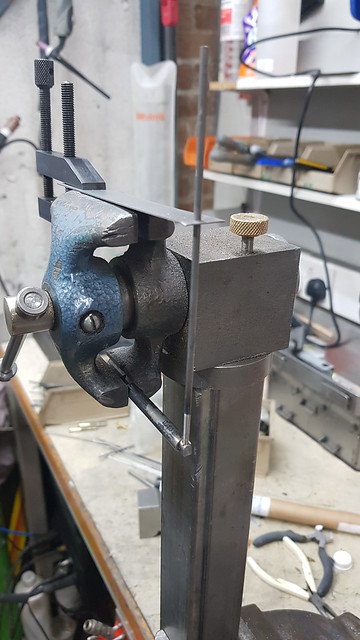 20200123_213539 20200123_213539 by The train Man, on Flickr I've smothered it in Medium Temperature flux which isn't really good enough, but it's all I've got for this.  20200123_213737 20200123_213737 by The train Man, on Flickr As you can see, you have to get this almost Orange before it melts!  20200123_213918 20200123_213918 by The train Man, on Flickr |
|
|
|
Post by Roger on Jan 24, 2020 22:57:08 GMT
Slow progress I'm afraid, I've scrapped the second handle too because I wasn't happy with the lineup of the handle. Third time lucky... Here I've attached a toolmaker's clamp to the flats on the body to show the alignment better. I used a piece of Silver Steel against one of the jaws to help line up the handle. The front to back adjustment is easier to check with a small square.  20200124_213619 20200124_213619 by The train Man, on Flickr It pays to crack on with it and get it hot quickly so the flux doesn't run out. I ought to get some for higher temperatures really, but I want to crack on and finish these. 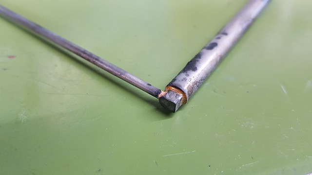 20200124_223421 20200124_223421 by The train Man, on Flickr Here I've set the Morse taper adaptor to the size of the handle and then moved it so it's on the edge of the handle so I can turn the rotary table to the right angle. I couldn't really use the clock because any slight change in height would mess up the reading.  20200124_224613 20200124_224613 by The train Man, on Flickr I'd actually machined the hex in the first one to see how that would go, and it turns out that the handle is pretty strongly attached using the Silicon Bronze brazing. |
|
|
|
Post by Roger on Jan 25, 2020 22:11:42 GMT
Putting the toolmaker's clamp here rather than lower down makes it much easier to check the alignment of the handle. I don't know why I didn't think of that before.  20200125_104752 20200125_104752 by The train Man, on Flickr It also helps to mix the flux a bit thicker so it forms a deeper coating and lasts longer.  20200125_110413 20200125_110413 by The train Man, on Flickr I'm heating this vigorously but well away from the thin handle so it doesn't get too hot. The C2 Silicon Bronze Brazing rod melts at 875C (1148K) which is a Bright Red colour. However, as usual it takes a bit more heat to get the whole thing to the point where it melts and flows into the joint. At that point it's heading into the Orange range. You really don't want to be holding the temperature that high for more than enough to see that it's melted the rod else it's going to end up badly oxidised. I turned the torch right down but kept the area warm so that the Red colour subsided gradually. I didn't want the Silver Steel to end up hard so it was brittle and impossible to cut or machine.  20200125_141206 20200125_141206 by The train Man, on Flickr The internal hex is roughed with a 1.5mm cutter after drilling the middle through with a 1.4mm PCB drill. It was then finished with a 1mm cutter.  20200125_115014 20200125_115014 by The train Man, on Flickr The shaft has a matching hex of course, and that's going on here.  20200125_162440 20200125_162440 by The train Man, on Flickr The real thing doesn't have a hex, I don't know how they are held on. However, you can see the shaft poking out of the end of the handle, so I've simulated that look. For some reason, I failed to finish the hex pocket on the third handle, so that will need carefully setting up again to do that. The one of the right has a Model Boat style coupling with a 1mm drive pin and a ball end. That's because the shaft to the bypass valve arrives at the back of the cab at an angle.  20200125_215126 20200125_215126 by The train Man, on Flickr The hex on the drive shaft with the coupling need to be set at the correct angle to the coupling slot, so I need a fixture to hold it for machining the hex. A piece of Aluminium bar will suffice for that. More on that tomorrow.  20200125_214827 20200125_214827 by The train Man, on Flickr |
|
|
|
Post by Roger on Jan 26, 2020 23:30:08 GMT
|
|
|
|
Post by Roger on Jan 27, 2020 22:25:32 GMT
This was fiddly to set up again, but with a bit of care, and sneaking up on the size, I managed to get this handle to be a nice close fit on the shaft hex.  20200127_104826 20200127_104826 by The train Man, on Flickr So this is the arrangement for the bypass valve. The LH end has a pocket with a slot across the end. The mating shaft is done at the end of this sequence.  20200127_105242 20200127_105242 by The train Man, on Flickr However, to Silver Solder the Injector water valve handles in the right orientation, I decided to make a couple of fixtures, one for each end to engage with the Male and Female hex ends.  20200127_193624 20200127_193624 by The train Man, on Flickr With those, it was simple to set the shafts vertically and lined up spot on. The hex fixtures are Stainless Steel so they won't get stuck and it won't conduct the heat that well. It's all smothered in flux as usual and a ring of 0.5mm diameter Silver Solder fitted just above the joint. I heated the clamped end, staying well away from the shaft until it was almost hot enough. It's easy to get the thinner parts much hotter than the chunky clamped parts.  20200127_212429 20200127_212429 by The train Man, on Flickr  20200127_214806 20200127_214806 by The train Man, on Flickr  20200127_221120 20200127_221120 by The train Man, on Flickr This is almost finished, there are just the cross drilled 1mm holes left to do for the bolts that hold these in place.  20200127_105451 20200127_105451 by The train Man, on Flickr This is the little Form tool to create the ball shape on the end of the Bypass Valve coupling.  20200127_164756 20200127_164756 by The train Man, on Flickr The shaft is 2.5mm daimeter Silver Steel. I'll add the cross drilled hole tomorrow.  20200127_171801 20200127_171801 by The train Man, on Flickr |
|
|
|
Post by Roger on Jan 28, 2020 12:18:38 GMT
Here's the cross drilled hole going into the coupling for the Bypass Valve handle. I've first drilled this with a 0.8mm diameter PCB drill, just gently touching the ball end to make sure it's had a good opportunity to centre itself. Here it's being finished with a 1.1mm HSS drill  20200128_095945 20200128_095945 by The train Man, on Flickr I've sacrificed a 1.1mm HSS drill to provide the pin which is Loctited in position here awaiting grinding to length. 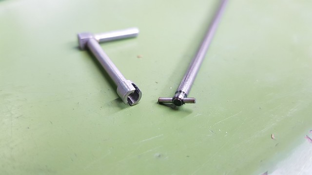 20200128_100905 20200128_100905 by The train Man, on Flickr The fixture came in handy for holding the coupling shaft while drilling the 1mm retaining hole across the edge of the hex shaft. It's all Silver Steel so there's no tendency to wander. I'm using a 0.8mm PCB drill for this too, before opening out with a HSS drill.  20200128_103805 20200128_103805 by The train Man, on Flickr  20200128_104236 20200128_104236 by The train Man, on Flickr  20200128_104953 20200128_104953 by The train Man, on Flickr The others were set up in a similar way. I've left enough shaft showing to allow me to use the wobbler on both sides.  20200128_112917 20200128_112917 by The train Man, on Flickr  20200128_115723 20200128_115723 by The train Man, on Flickr All done and last!  20200128_120643 20200128_120643 by The train Man, on Flickr |
|
|
|
Post by Roger on Jan 28, 2020 21:44:18 GMT
Time to finally start connecting the bypass valve handle in the cab to the valve between the frames. This is the bracket on the inside of the frame above the valve. The bush is PB102 and has been riveted and Loctited to the bracket and then clocked up again over the outside to finish the hole and rear details.  20200128_210717 20200128_210717 by The train Man, on Flickr There's an arm that has to be attached to the rod.  20200128_213139 20200128_213139 by The train Man, on Flickr  20200128_213151 20200128_213151 by The train Man, on Flickr |
|
|
|
Post by Roger on Jan 29, 2020 18:43:09 GMT
I sprayed a few thin coats onto the corners of the cab where the top was joined to the sides so I could see whether there was any further need for filler.  20200129_133700 20200129_133700 by The train Man, on Flickr It looks good enough to me, so that was stripped off...  20200129_133752 20200129_133752 by The train Man, on Flickr ... so that the gutters could be riveted on. I've only got dome headed rivets and the need to vanish on both sides, so I countersunk them a little and made sure to form the rivets enough to deform into those.  20200129_165142 20200129_165142 by The train Man, on Flickr  20200129_165223 20200129_165223 by The train Man, on Flickr Both gutters were then filed off...  20200129_183307 20200129_183307 by The train Man, on Flickr ... and on the inside as well. They're a real mess on 1501, with long beads of rough welding in half a dozen places holding them in place. I'm not going to be modelling that!  20200129_183335 20200129_183335 by The train Man, on Flickr |
|
|
|
Post by Roger on Jan 30, 2020 16:14:32 GMT
I've somehow managed to mislay the nut spinner and the Yellow M1.4 driver that was in it. I've searched high and low for it, and it's nowhere to be found. So here are a couple of new ones, both shorter than the original, which hopefully will re-appear at some point. I've taken the opportunity to improve the design by using a 4mm magnet in the front instead of the original 3mm one which didn't hold in the drivers with the larger through hole that well. I've also used a 3mm magnet to hold in the spinner with a flat end to that so it holds in better. It's removably because sometimes you need to get in tighter spots and it needs to come off. I've colour coded all of the small nut sizes so I can quickly put my hand on the right one.  20200130_160720 20200130_160720 by The train Man, on Flickr |
|