|
|
Post by 92220 on Jan 24, 2018 11:13:32 GMT
Are the holes in the right place David? Yes he has them right. They match the BR detail drawing SL/BR/880 Rear Buffer Beam Arrangement.
Bob.
|
|
|
|
Post by vulcanbomber on Jan 24, 2018 20:00:01 GMT
......Thanks Phil......
Phil is taking the biscuit out of something i havnt come clean about yet.. all in good time.
|
|
|
|
Post by vulcanbomber on Mar 3, 2018 0:57:41 GMT
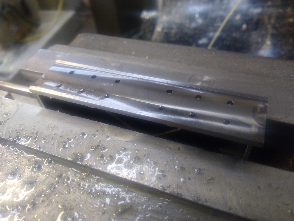
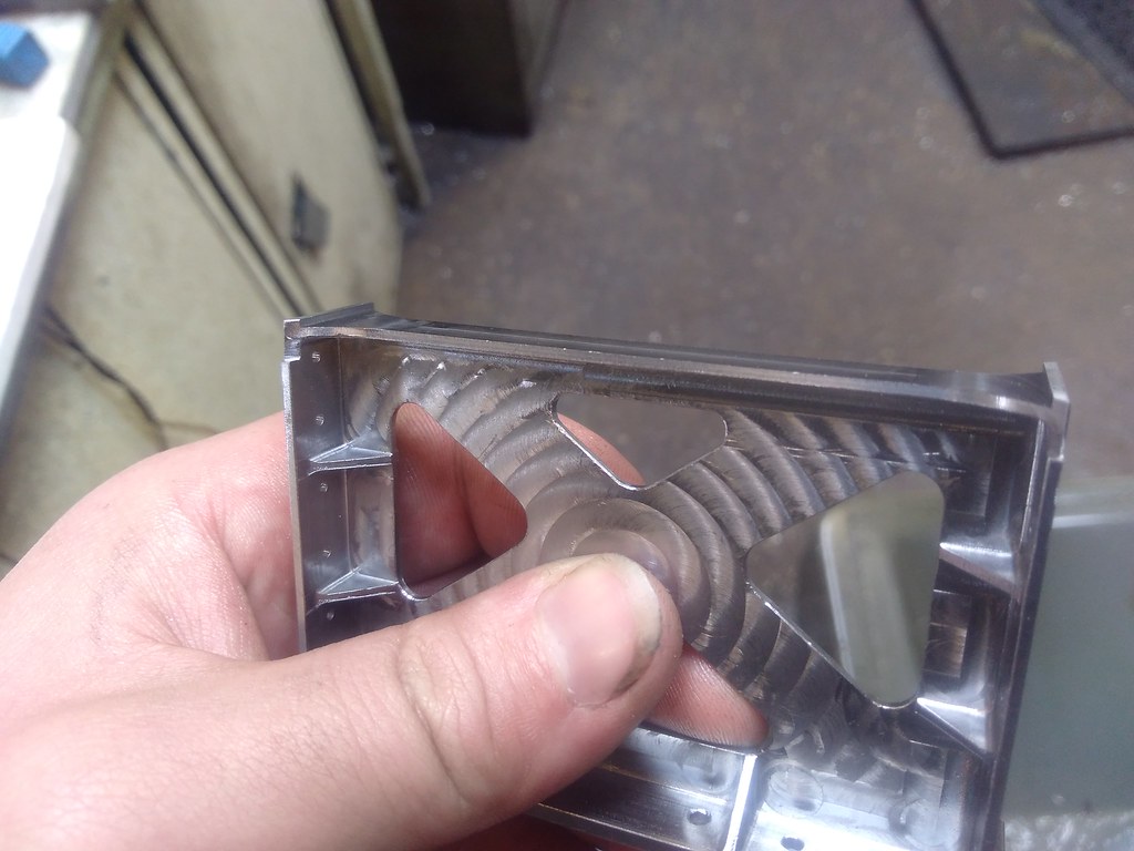
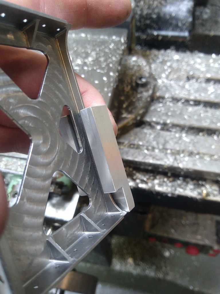
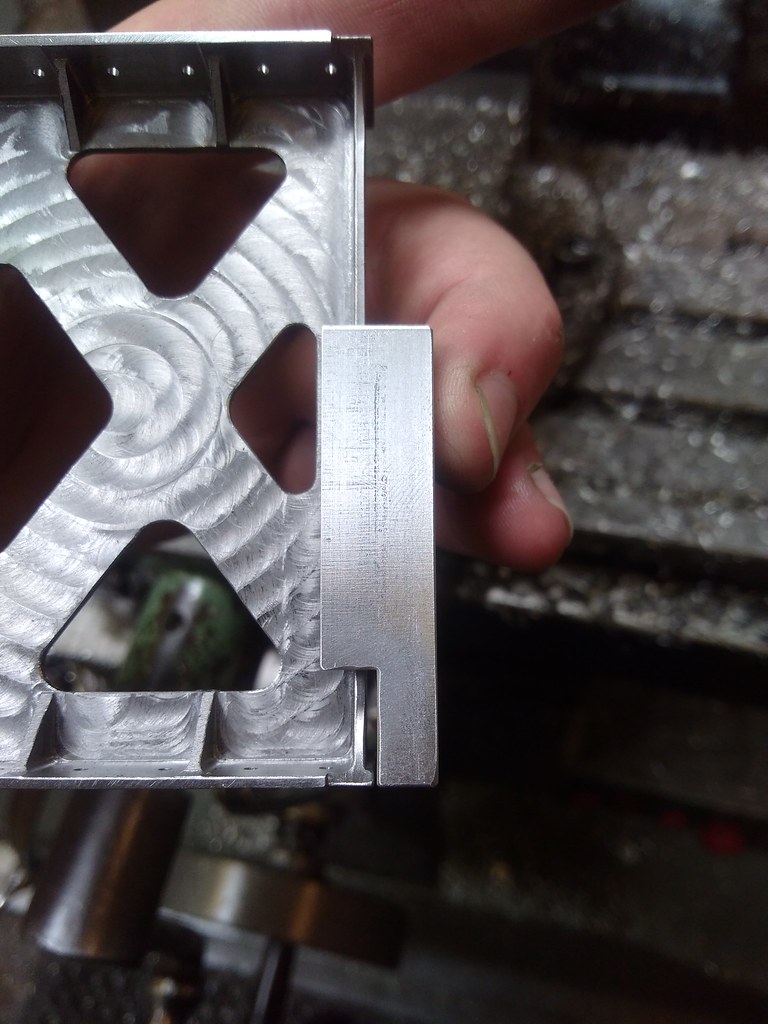
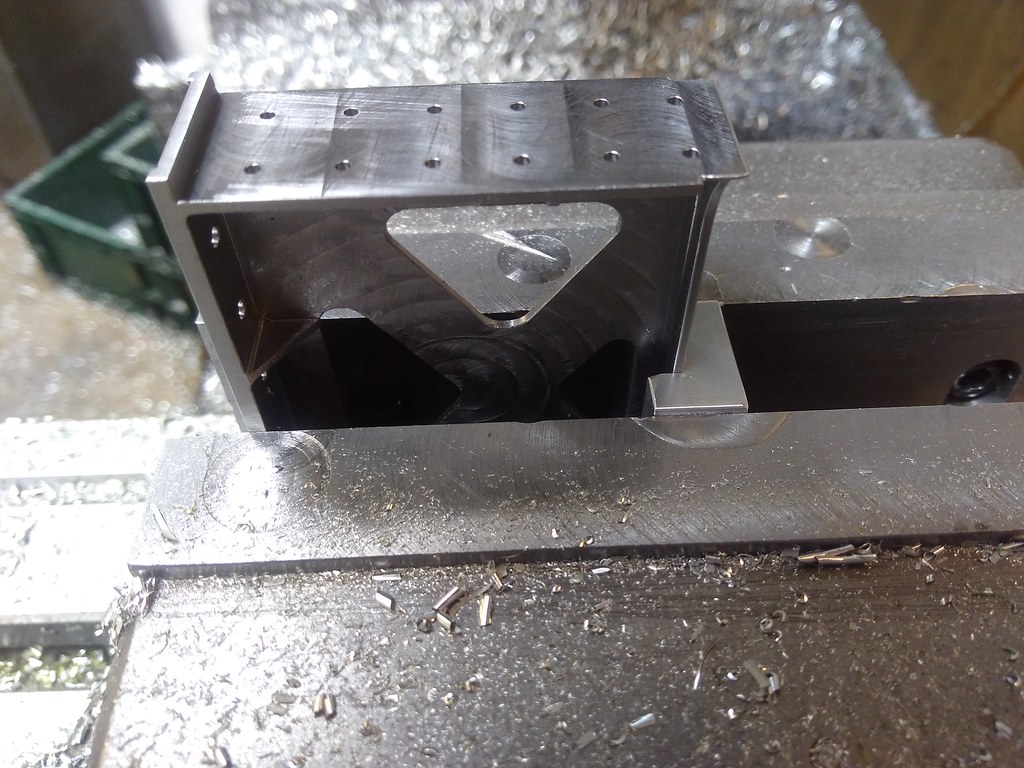
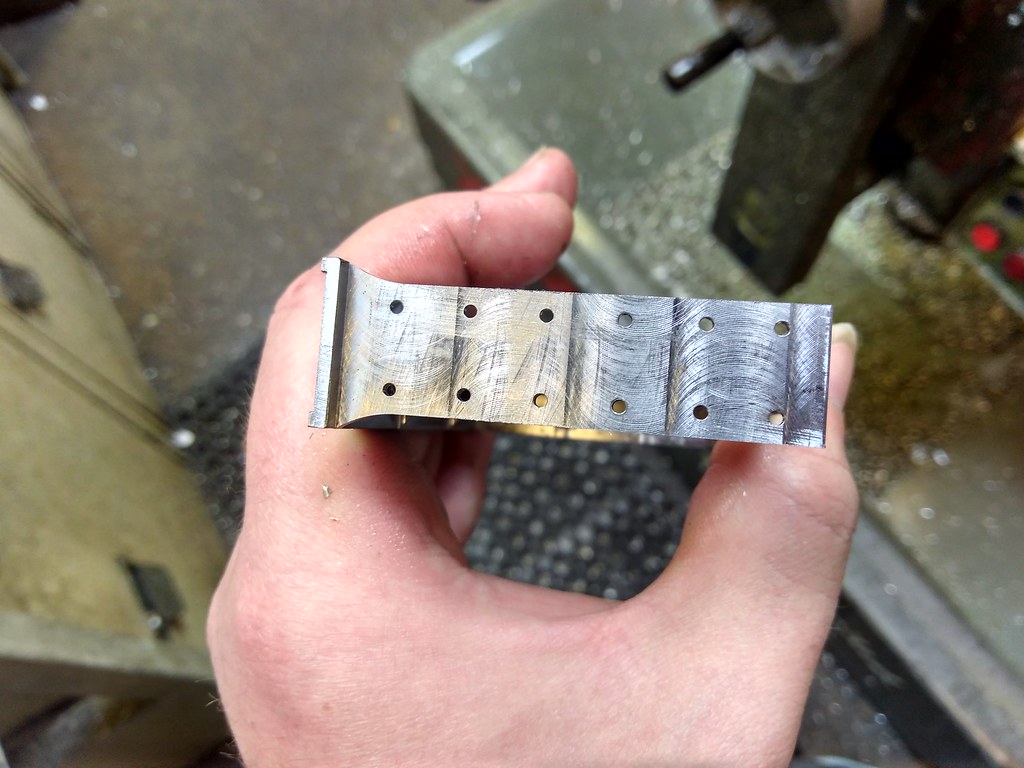
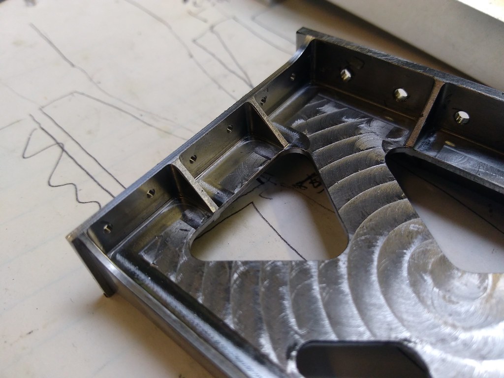
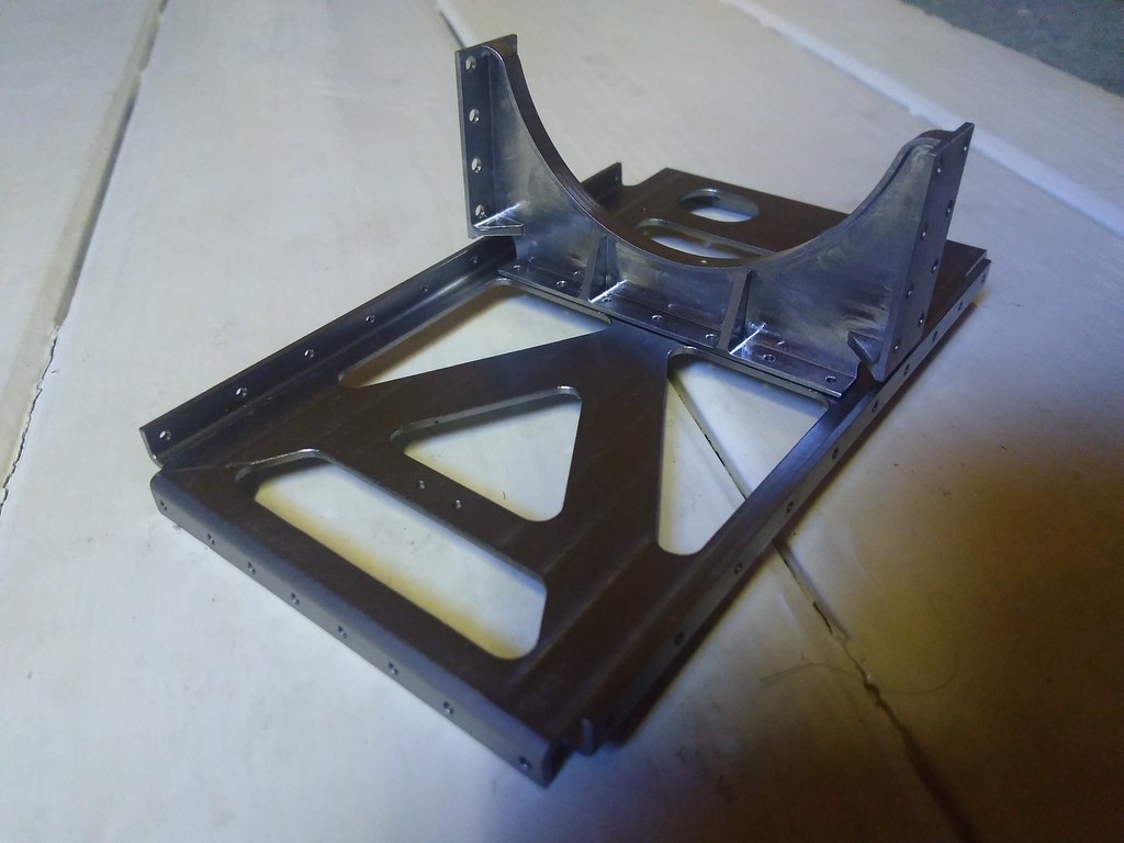
Finally found some time for your next update, i've actually done a few different thing since my last one. First thing was to make a fixture for the Rubbing blocks. That looks something like this, hopefully you will see it in action soon. 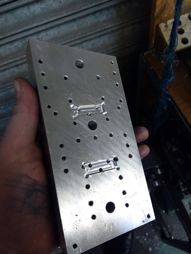 I've also machined to thickness and Drilled the stretcher Ed had started. 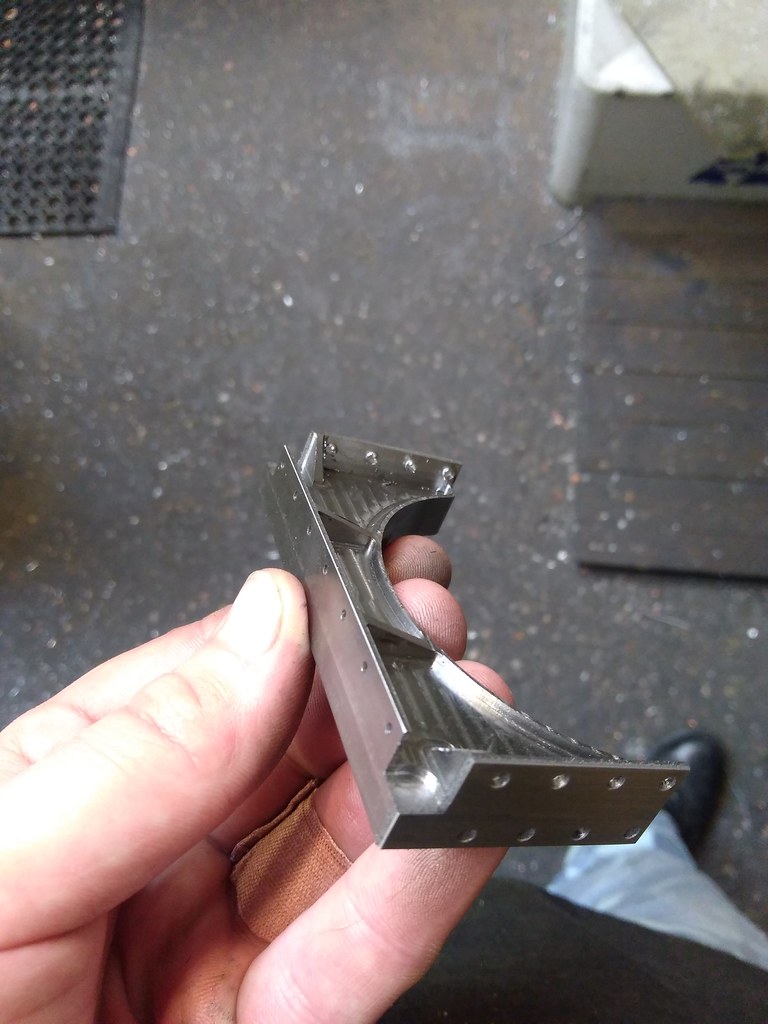 I then made fixtures and clamps finish these off. 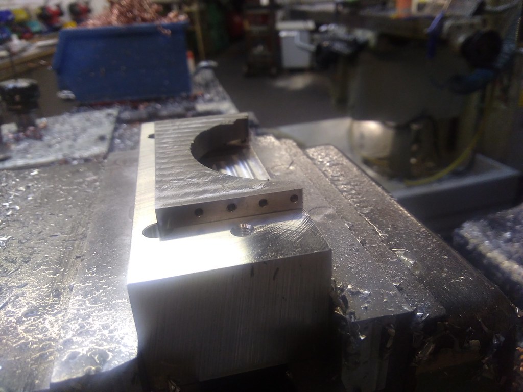 The Stretcher is now with Ed again for him to finish off for me. Next, i've made some decent head way into yet another Stretcher, this one is the Boiler Support Stretcher and again, its milled from solid, the full size ones were fabricated. The works drawing for this is no longer available so Bob has kindly let me use the drawing he made to do his. I watched some time ago one of out professional millers at work teach the apprentice how to block something out, the apprentice followed the instructions to the letter and made a Rhomboid, not a square block as planned. The stretcher needed blocking out first so i've taken some pics, and will attempt to explain what I do to you guys. Hope a few find it helpful. Oh and make sure your head is square to your table. First take your billet, remove the burrs and throw it into your vice and clean up your BIGGEST face..... Oh and make sure your head is square to your table. 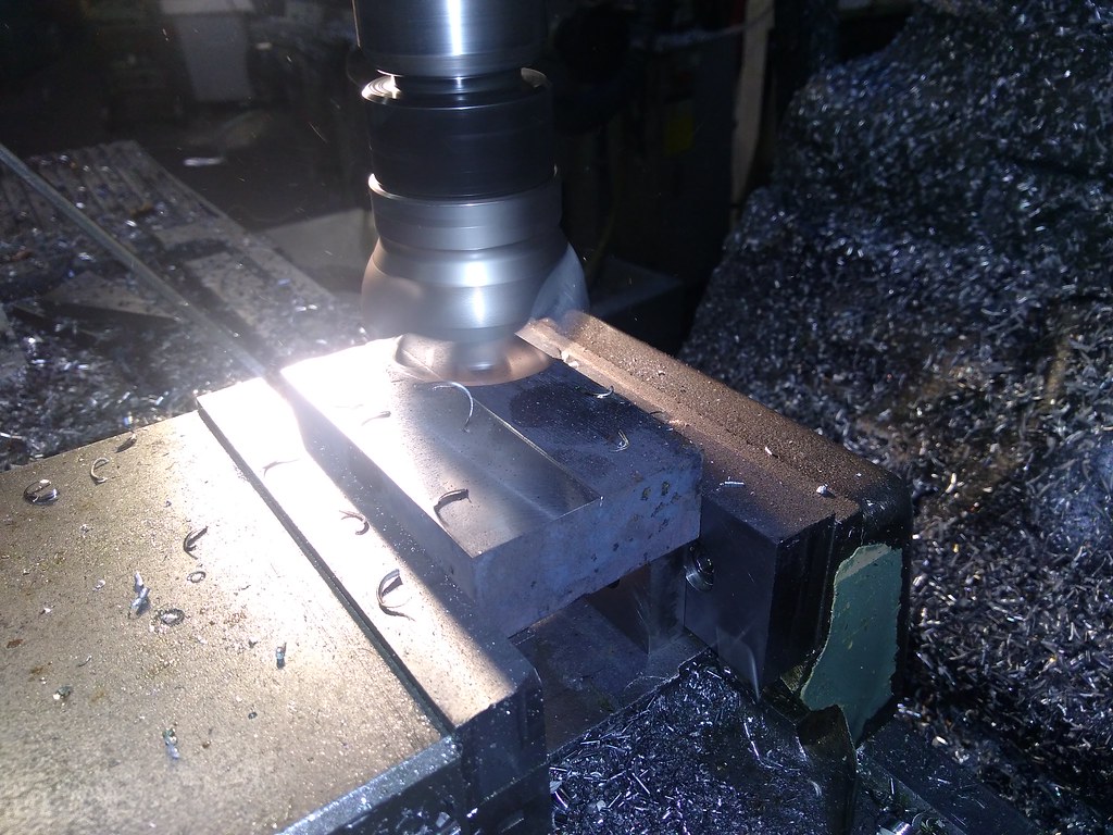 once this face is cleaned up, it becomes your datum face. Next remove the burrs, then the freshly machined face goes up against the vices fixed jaw. You then need a roller, and the lower it is in the vice the better. The roller is used to get rid of the effect of the moving jaw lifting when tightening the vice. A gentle tap with a mallet can be used to get the job down, i never bother. 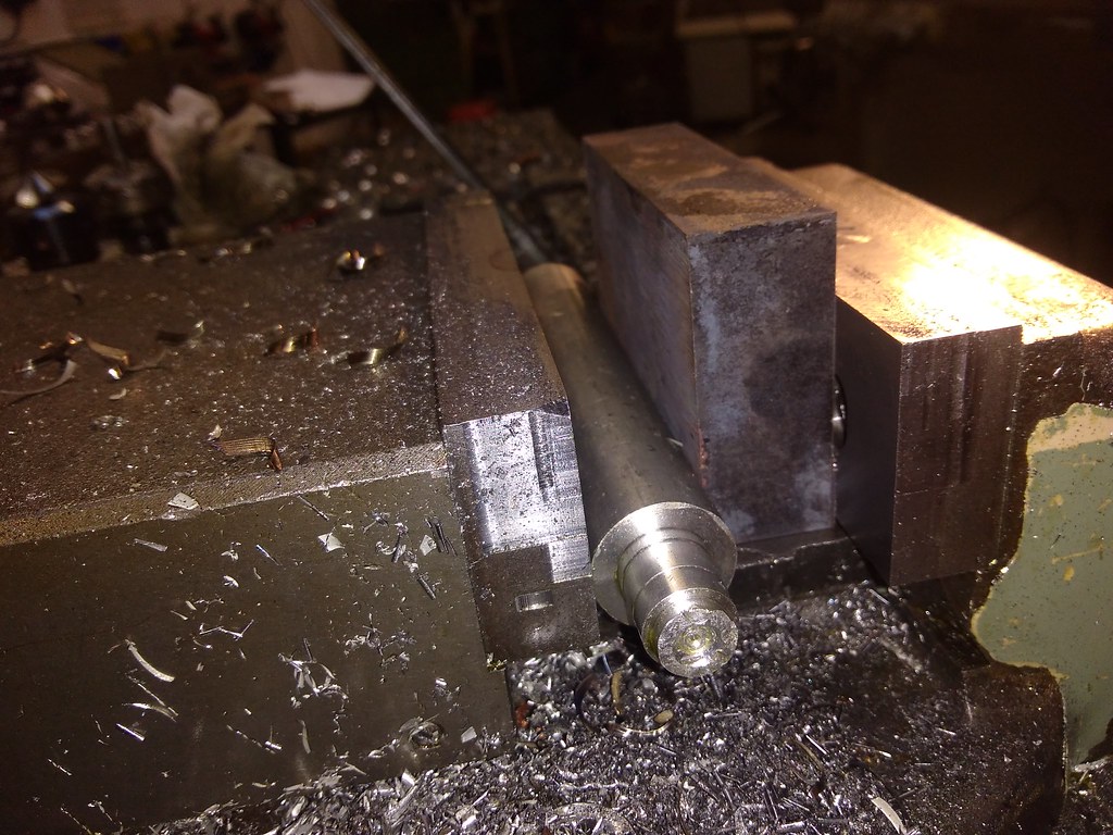 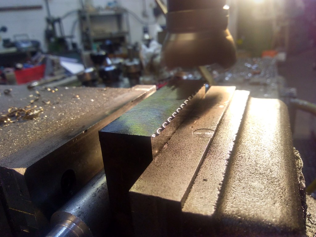 one of the joys of carbide insert face mills is the wicked burr the throw over, for people that use these, take a light cut (say 0.25mm) coming back the other way, that will then weaken the burr so it just peels off with fingers. 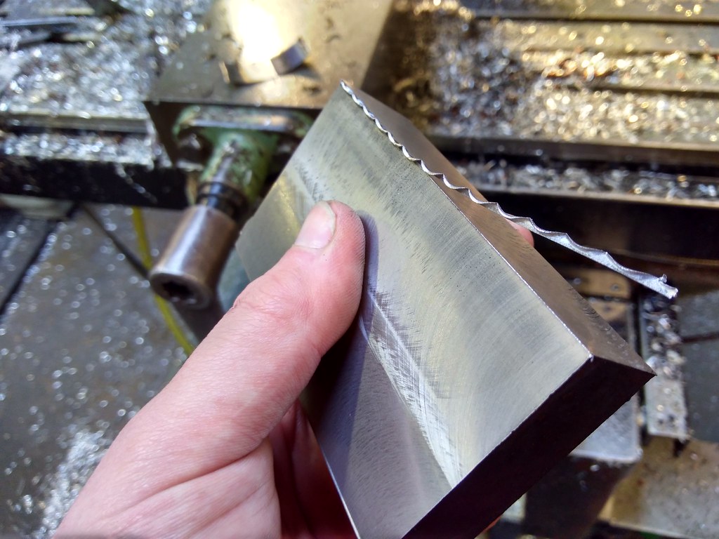 I then use a very technical device to remove the bit of burr that's left. 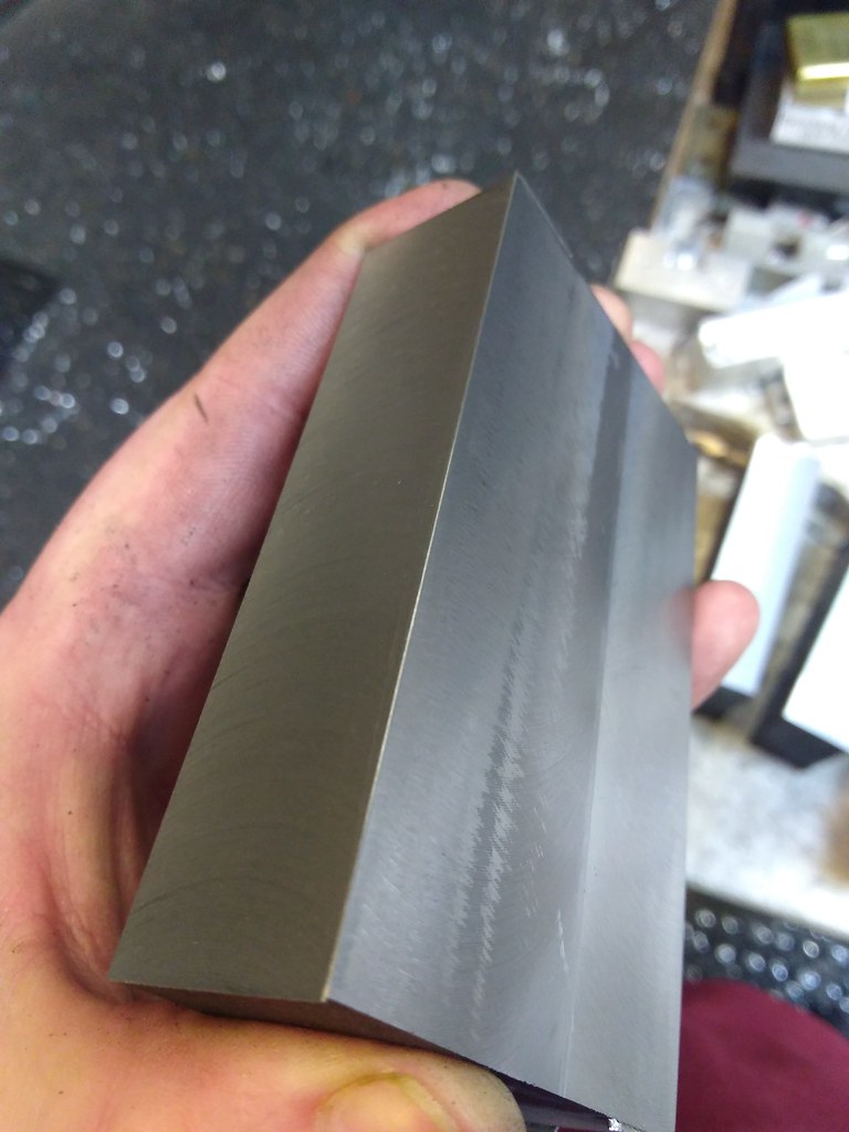 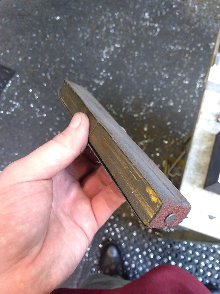 The 3rd face to machine is the one opposite the one you have just done, remember the first face goes against the fixed jaw, still use the roller and this time tap the job down to the parallels and you can bring this dimension into size. Now, if you can put the 2nd face onto a flat surface and a clock onto the 3rd face (or vise versa) any error the clock detects is in your vise, the block i was doing was about 24mm wide at this point and the total indicated error was 0.0005" which is in fact double the error in the vise. (because you have machined both faces from a common datum) Now i'm lucky to have access to some wonderful kit, but that vise is only that good because of the time spent packing out the fixed jaw with bits of fag paper ect. A little bit of trial and error should also get you a good vice. Assuming everything is ok, you can now go onto the 4th face, which is the unmachined big face. You can now find out how good things are because the block should tap down to trap both parallels, if a parallel can be moved its not down, normally if the parallel next to the moving jaw is free then the moving jaw is lifting the component, use a bigger mallet, don't tighten the vice so much. If there's a lot to come off, tighten the vice, remove the bulk, then undo and re nip the vice and tap the block down again. If the fixed jaws parallel is free but the other isn't free then your 2nd and 3rd faces are not square to the datum face. 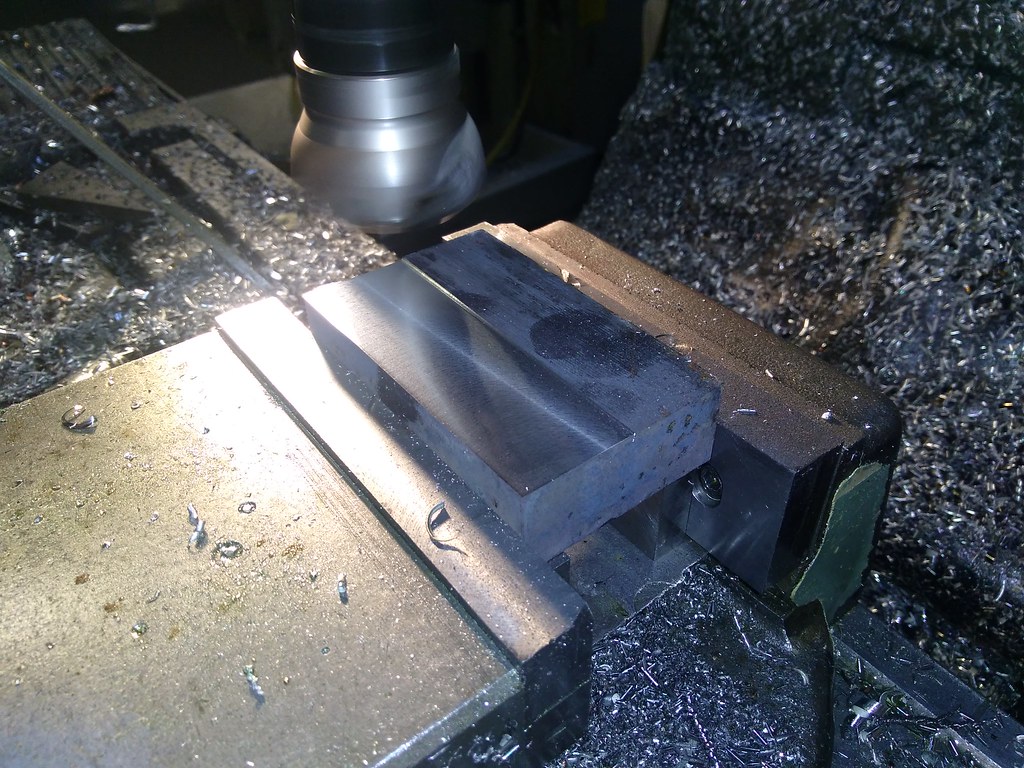 We can also finish this dimension to size. We now have 2 faces left, i used an end mill to clean 1 end up on these. 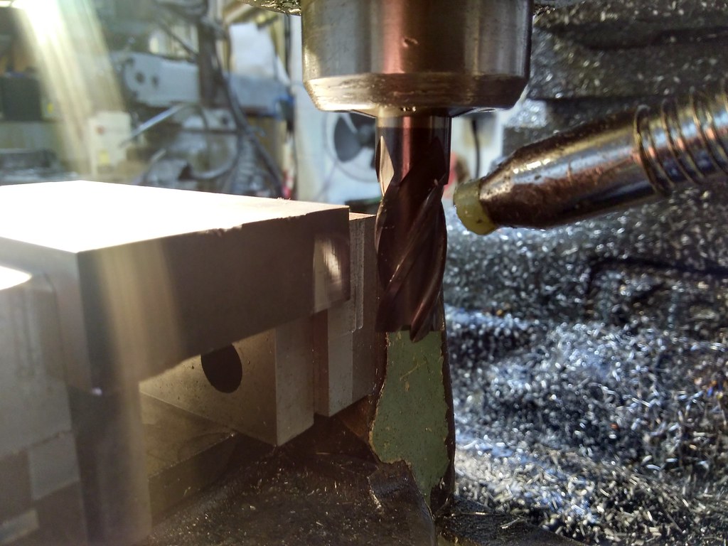 And in this instance i also did this to finish the final face and the final dimension, I could of stood it up to machine the last face with the face mill. For stuff to big for the vice, you can use this setup and machine a register, then you can put an angle plate on the mill clamping the datum face to the plate and using the register either clock it true or sit the register on a parallel that's on the machine table, i'll try and demonstrate this at a later date. Hopefully that makes sense and a few of you find it useful. The stretcher has progressed a lot further than that. After blocking out, I machined the step for the frame spacing and drilled the rivet holes. 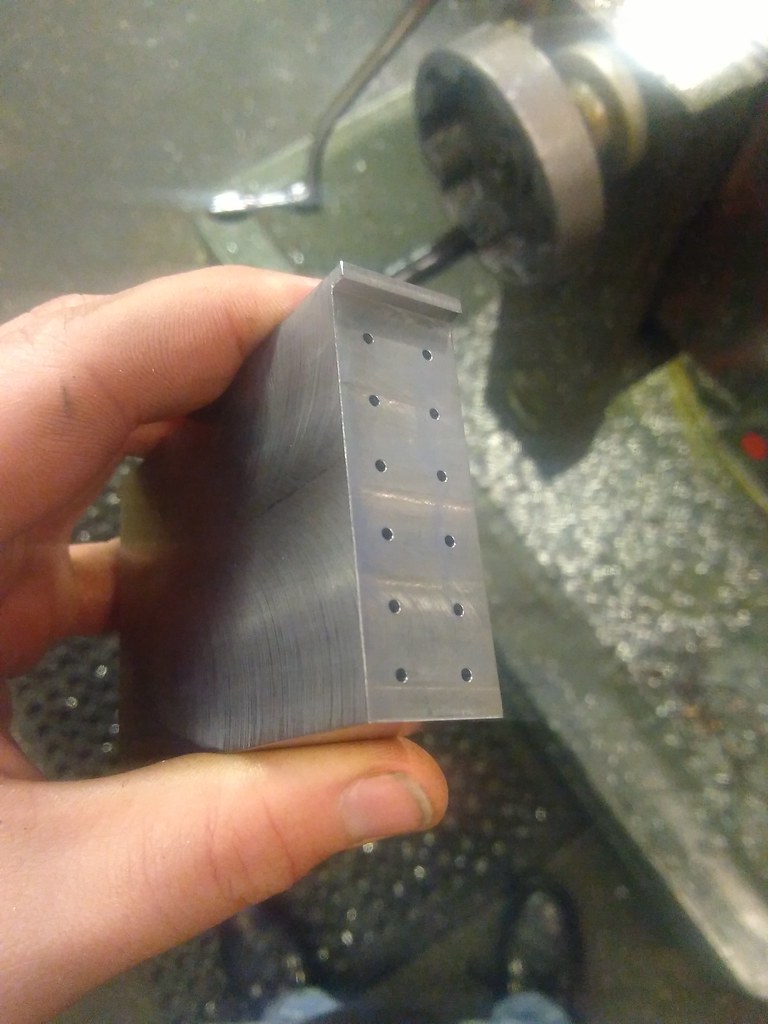 This is the same both sides. I've then machined out the 4 triangular shaped pockets. The rectangular pocket was done to allow me to get to where i needed to be with a 4mm cutter to machine the small triangular detail at the bottom of it. 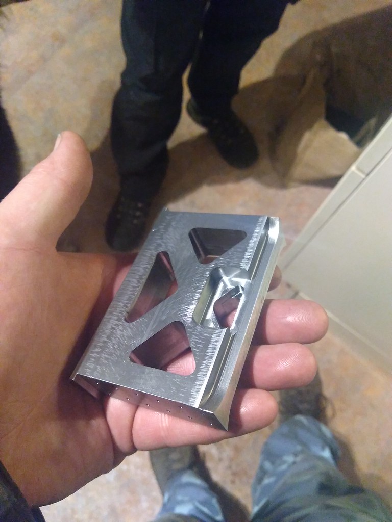 In that picture you should see the shape milled into the bottom, this is the same both sides. The stretcher is now with Ed to machine the middle out of it. It involves a lot of nibbling out corners with a very small tool which he is better equipped for. Thanks for looking in. |
|
|
|
Post by 92220 on Mar 3, 2018 9:11:02 GMT
Super bit of machining David!
Bob.
|
|
|
|
Post by vulcanbomber on May 11, 2018 22:27:05 GMT
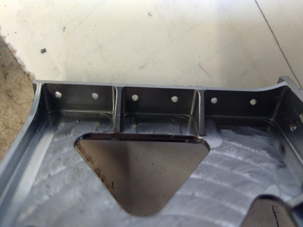
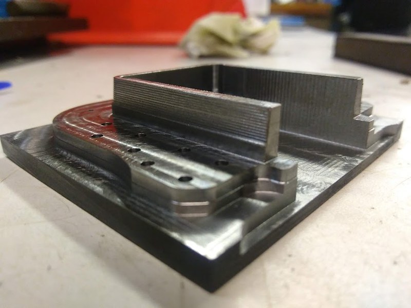
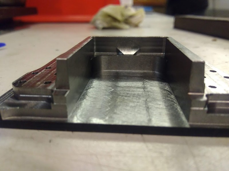
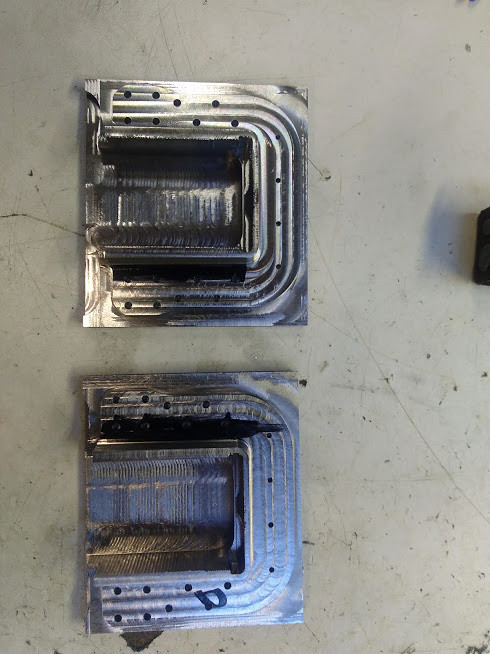
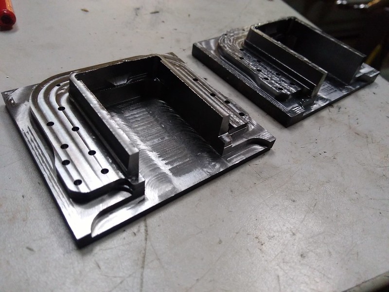
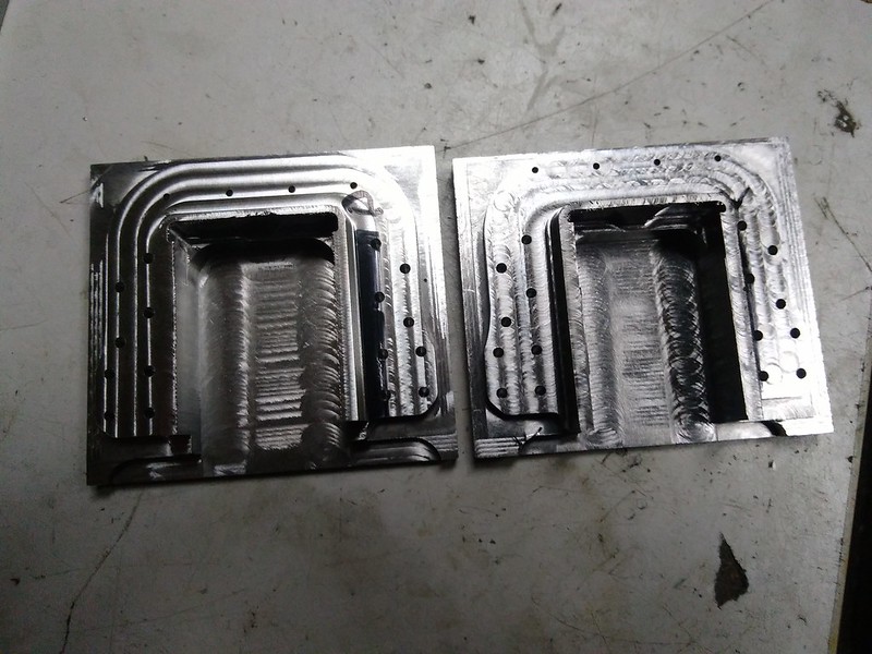
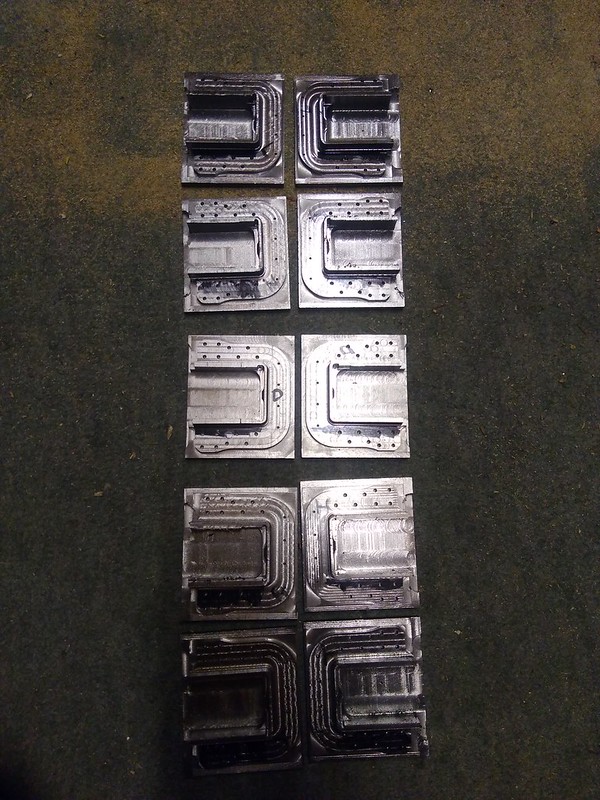
Bit slack on getting this update done but here it is. First thing to show is the Boiler Support Stretcher I left with Ed, which has now had the middles removed. 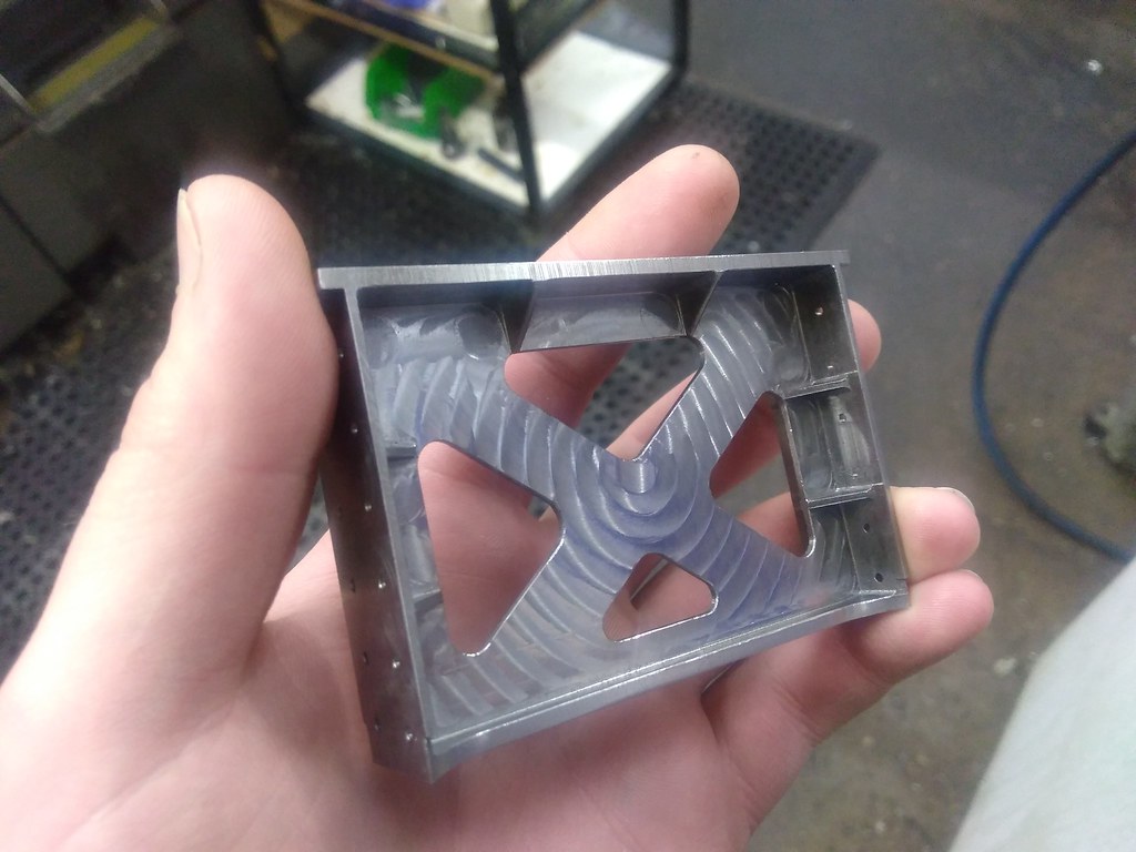 I'm very happy with this, I need to do a little bit more work on these, which I will get to soon all being well. Ive Kept myself occupied with the Rear Intermediate rubbing blocks, these have spent a huge amount of time on the machine with little to actually see. They have also Been set up more than a few times because of the machine being needed for works work, hence you'll see the fixture clamped to the table and then sat in the vice, then sat in the vice on different parallels. First thing i wanted to do was machine the sides with there angle. this was done by stepping up with the Z and Y axis of the machine and using its repeat function, so I wrote 2 lines of program and using the repeats offset function it wrote the other few hundred lines for me. 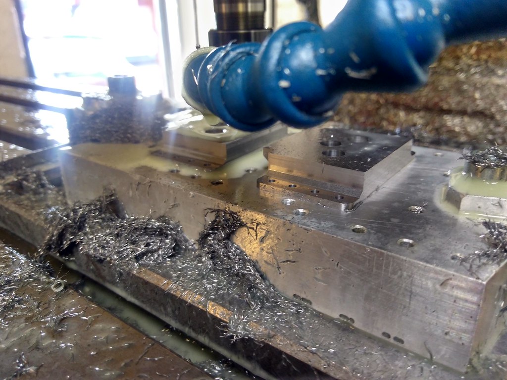 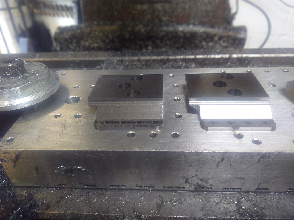 Next I formed the radius that is the working face, I have slightly simplified this, when there finished I will put a picture up of the real thing so you can see the difference. The biggest ball nose cutter I can use is 2.5mm or 0.100" in old money so that's what i am using. the radius is forms on the Y and Z axis, The X was stepping over 0.05mm for each pass, so these took 6 1/2 hrs to do a pair of blocks. 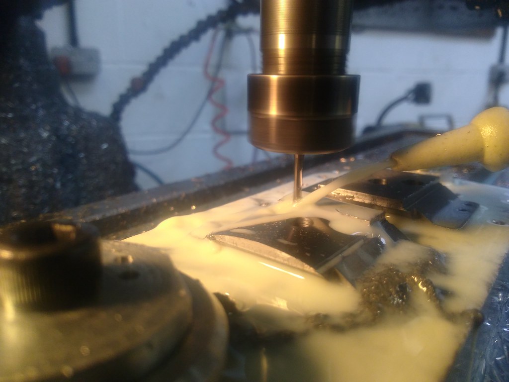 And finally, while we had a fitter in at work this evening removing a Ball Screw from one of the Lathes I jumped at the chance to start the next bit..... Which is produce the ribs. if you look closely you will notice in the left had pocket there's a sort of lump, this was addressed after the pictures taken, just a case of tweaking the cutter length. 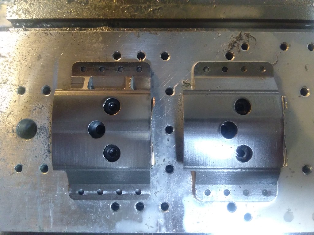  Again, i've written 7 lines of program to remove all that material, the machines repeat copy function doing the rest. I now need to do the same on the other side, again 7 lines of program because the pockets will be approached slightly differently so we are always Climb Milling... I will then be able to copy the whole program with 1 line of program to machine the 2nd Rubbing Block on the fixture. Again, this will probably take most of the day to run quietly in the background. More soon for you hopefully. |
|
|
|
Post by vulcanbomber on May 20, 2018 21:36:32 GMT
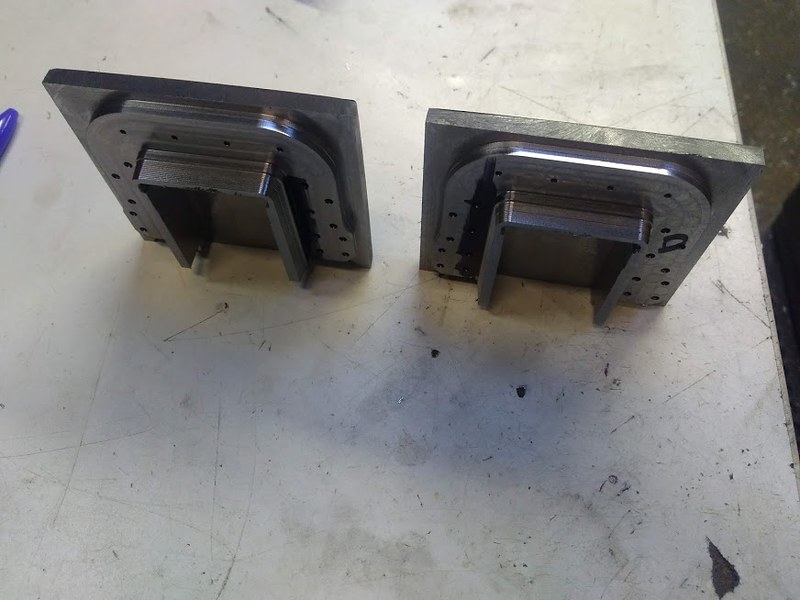
Bit more to see on the 9F, the Rubbing blocks have been finished now, I'm very happy with how these have turned out. The last update showed the start of the ribs that are on either side, I finished this, then made some clamps up to hold the Blocks down while I machined out the center slot. 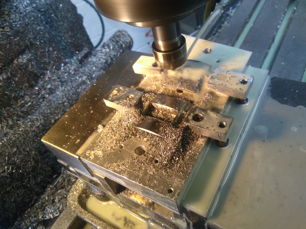 And the last think I did was give them a good mopping on our mop wheel at work, to remove the worst of the Ball noses machine marks and the burrs on the ribs. Leaving the final product like this. 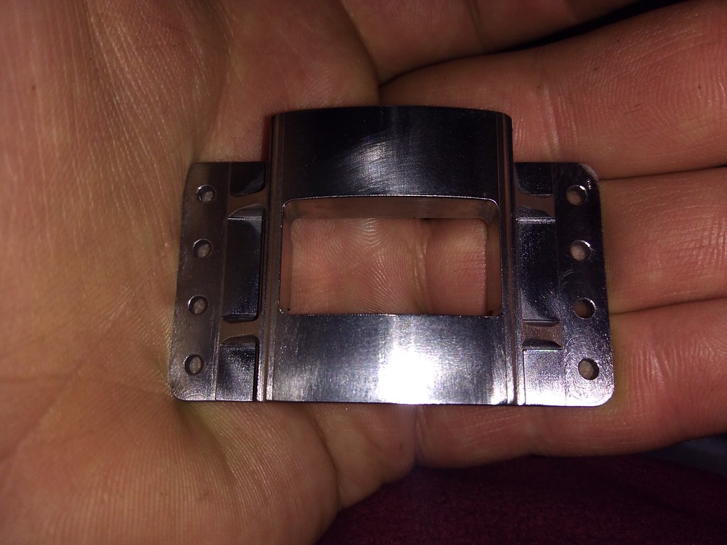 And on the Rear Buffer Beam. 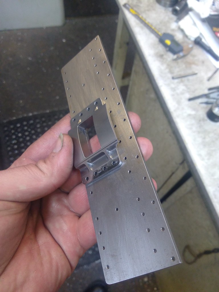 This has reminded me that the Rear Beams slot needs adjusting which I forgot to do when I drilled it... Which I will do in the next week or 2. I also collected a small bit of Exciting laser cutting from Doncaster. 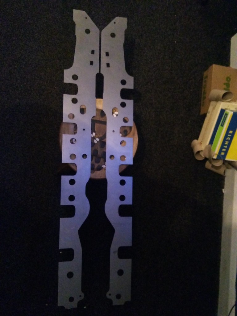  Yep, I have the frame plates at last. Hopefully the 2nd picture shows the slight variations between the 2 sides. More again soon hopefully. |
|
|
|
Post by vulcanbomber on Jun 17, 2018 21:34:39 GMT
Hello again readers, I've been a bit slack on this update, but it does show something else finished.
The item in question is the Boiler Support Stretcher, last time I showed this it had just returned from Ed who had chomped the middle out.
The first think I had to do was drill and ream some holes that hold the Support Shoe, something that wont be made for a long time yet, I also milled the slot that a packing piece fits into.
Followed by milling the bottom away to produce the overhang from the 2 side plates (remember at 12 inches to the foot, this was fabricated).
And finally the side plates had to be shaped, I left this until the end because it made holding them on all the other ops a doddle. To hold the Stretcher I made up a small packing piece with a slot in. This allowed this op to be done in the vice.
And after milling the shape, turning the Stretcher over and repeating we had this.
And with that, that Stretcher is now finished and ready to go between the frame plate.....
Now, its been pointed out to me, by someone that doesn't use the forum that the frames i've had cut are incorrect. I've had them cut to the original drawing which in its notes covers 9F 92979. However, it seems there is a much later drawing which covers 92079 as well, it seems the original drawing was used up to locomotive 92049, then the later drawing used. So I am about to order the later drawing to see if these plates that are cut can be changed or are about to become a source of 3mm plate.
Also, if anyone wants a boiler support stretcher, I actually have a spare... and it will fit between the Les Warnett frames with just alterations to the holes. PM me if your interested.
Thanks for looking in.
|
|
|
|
Post by 92220 on Jun 18, 2018 16:42:07 GMT
Hi David.
The frame plates you have had cut, are for a 9f with welded horns. I've just sent you an email. Before you order new frame plates, I am sure you can easily modify the plates you have, by making the 2 different top edge radii the same as the larger one, and the horn slots opened out for cast/machined/fabricated hornblocks. When you get it, the drawing SL/DE/22051 should give you the necessary info for doing this. Hope that helps.
Bob.
|
|
|
|
Post by vulcanbomber on Jul 10, 2018 18:58:01 GMT
Evening readers, not a lot to report at the minute, machine time has been spent making some repairs to a Modelworks King Arthur model, not what i want to be doing but its becomes funds for the 9F so its not all bad.
On the 9F front, because the weather has been so perfect for it, I had my first ever go at Silver Soldering.
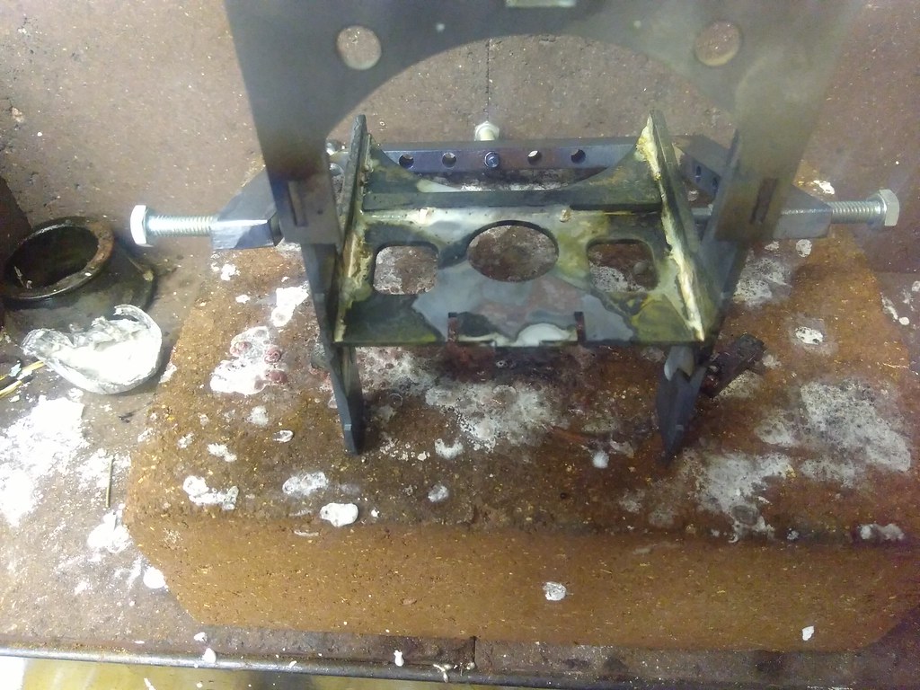
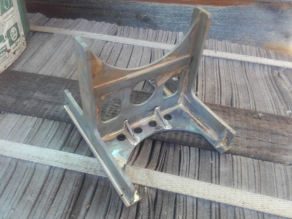
The bits in question are the Vertical Stretchers that I made all the parts for some time back, they were done in 2 heatings, which looking back was probably a mistake, they bent somewhat. first heating put the sides onto the center upright. 2nd heating put the base and gussets on.... that was after much fitting, hammering, cursing and swearing.. Still after first heat we had this.
we than acid bathed, attached the base, and then acid bathed again and look like the photo below.
These will hopefully get my attention soon at work, the 2 sides need machining to size, the rivet holes adding and also the "pad" in the center upright needs machining and drilling.
Thanks for looking.
|
|
|
|
Post by Deleted on Jul 10, 2018 19:32:28 GMT
Not an easy job to tackle as your first attempt in silver soldering...the end result looks great...well done sir..
Pete
|
|
|
|
Post by vulcanbomber on Jul 16, 2018 21:05:33 GMT
Another update in less than a week, wonder how long this pace will last...?
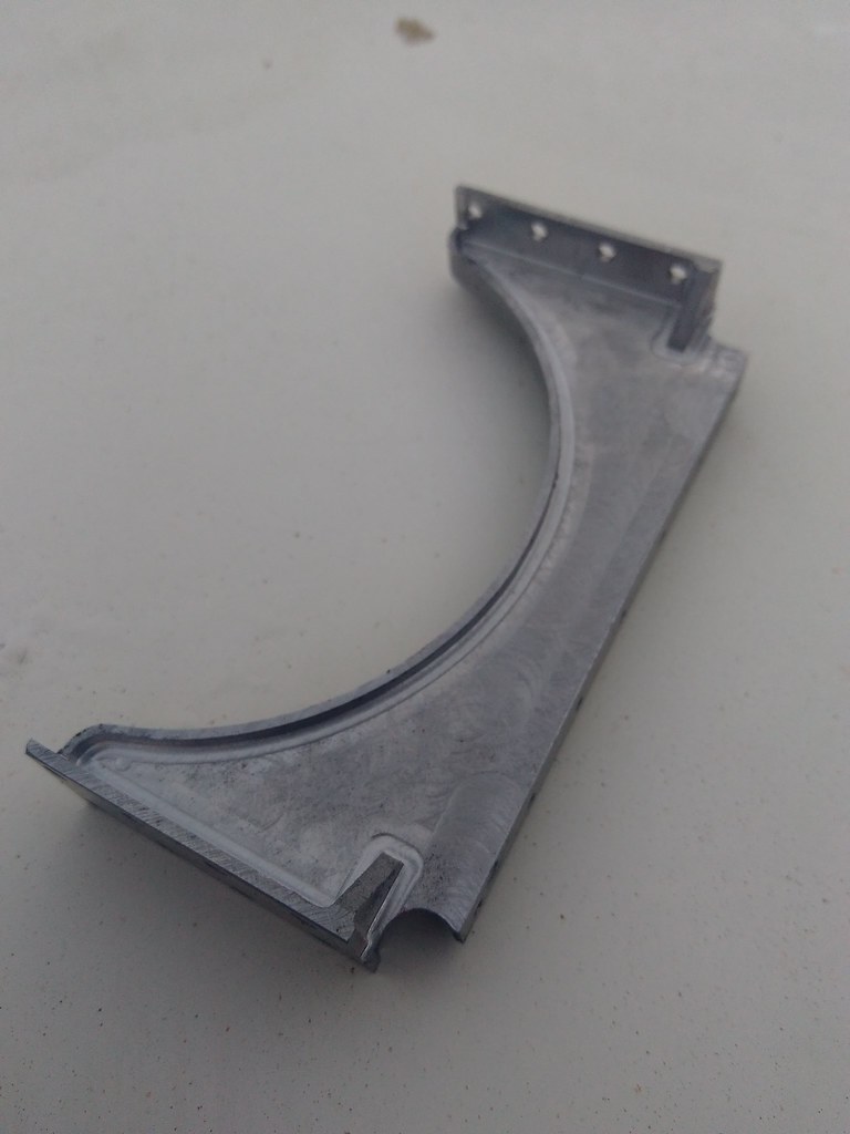
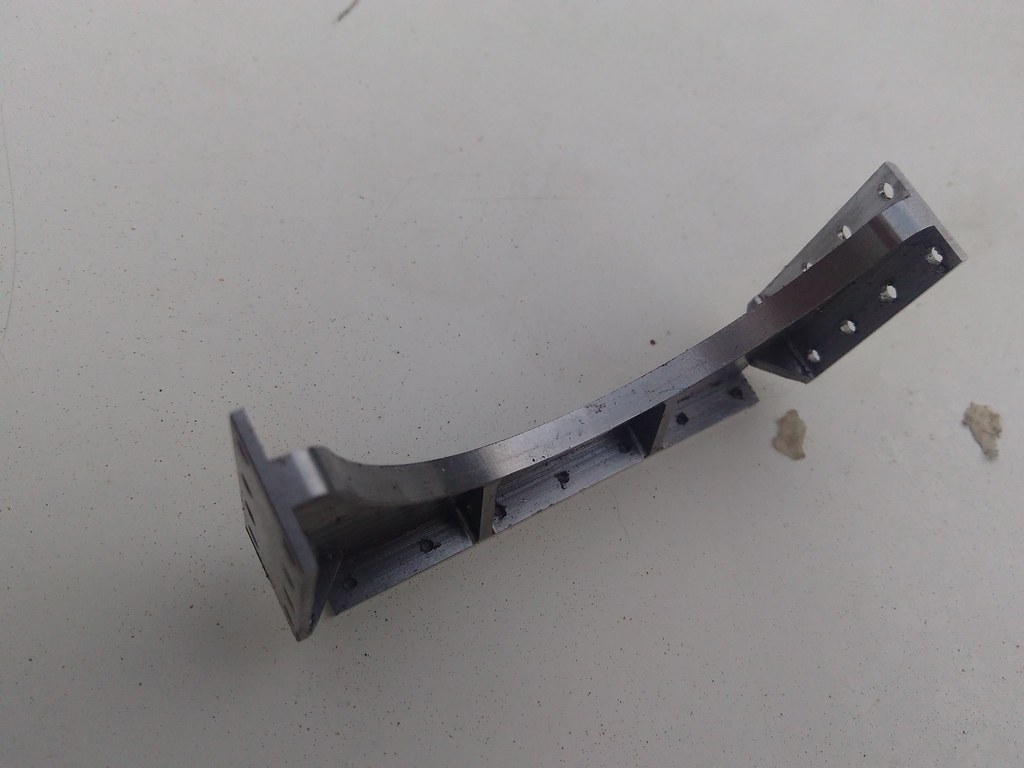
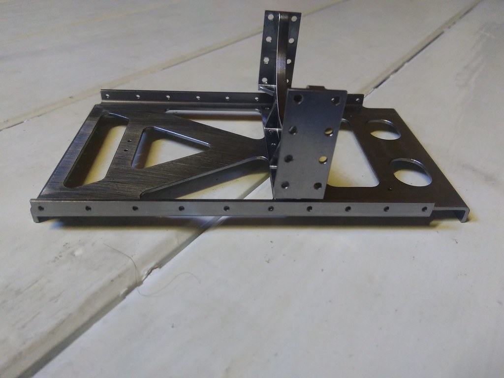
I cant take any credit for this, its Ed thats finished this, Its the Vertical Stretcher he has had for finishing.
And the next 2 pictures show it sat on top of the Horizontal Stretcher it lives with.
There will probably be a bit of a gap now until the next update, i've got some bits to do for Ed's build and a couple of bits to machine up for my Land Rover.
Thanks for looking.
|
|
|
|
Post by 92220 on Jul 17, 2018 7:52:25 GMT
Really nice work David!
Bob.
|
|
|
|
Post by Doug on Jul 17, 2018 17:35:58 GMT
Can’t wait to see this lot go between the frames very nice work  |
|
|
|
Post by vulcanbomber on Jul 17, 2018 17:51:40 GMT
Can’t wait to see this lot go between the frames very nice work Your not the only one! Be nice to have a lump to look at instead of a box of bits in a shoe box in the loft. |
|
|
|
Post by vulcanbomber on Nov 2, 2018 20:45:35 GMT
Well, this gap in proceedings has become somewhat larger than I wanted, the last few months have been trying to say the least having found out my dad (who has contributed far more to this build than I have give him credit for and probably doesnt actually realise how much he has done) has Bowel and Liver Cancer. Anyway he seems to be responding well to chemo so that has allowed me to get my head stuck back into the 9F for a bit.
I decided I'd make a start producing the Horn Blocks, so the Drivers Horn Blocks are now machined on the inside.
While the tooling is in the machine I will do the Leading, Intermediate and Trailing Horns like this although they are smaller, i'll again need a fixture to do the 2nd side but they will all, fit into 1 fixture.
Thanks for looking in.
|
|
|
|
Post by Roger on Nov 2, 2018 22:35:05 GMT
A cracking job as always. Sorry to hear of your Dad's illness, I'm sure everyone here will want to wish him well.
|
|
|
|
Post by David on Nov 6, 2018 0:19:50 GMT
Beautiful work, it's going to look awesome when you bolt the frames together with all those excellent brackets and spacers! The rubbing blocks are really nice too.
Best of luck to your father.
|
|
|
|
Post by 92220 on Nov 6, 2018 9:04:32 GMT
Lovely job David. Those stretchers and horns look superb, as all the parts you've done.
Very best of luck to your Dad.
Bob.
|
|
|
|
Post by Deleted on Nov 6, 2018 11:26:25 GMT
great work and all my best wishes for your Father David....
Kind regards
Pete
|
|
|
|
Post by vulcanbomber on Feb 8, 2019 19:04:58 GMT
Well, another huge gap in updates, but this one is full of excitement... first things first though.
Since my last update ive been making the rest of the horn blocks, the driving horn blocks on the 9F are slightly larger than the rest so thats why i did the drivers first... other than the 4 bolt holes on the top, the Leading, Intermediate and Trailing horns are the same on the 9F.
In the first picture, the closest horn is a driver, see if you can spot the mistake....
2nd pic again shows a driver and a driven horn
and the 3rd shows all 10 (sorry for the quality, taking pictures with your phone in the attic is not ideal.)
And now to the excitement....
Over that few months with dad being ill he's talked with me a lot about what to do with his retirement pot because basically we dont know how long he has got so as far as he is concerned, he doesn't need it. What he has concluded is to help me start up a small Machining business of my own.
We have bought a CNC Lathe, a manual lathe and a Pair of Prototrak equipped milling machines.
So, if anyone wants any help machining parts for there builds, please do get in contact with me, because i would be more than happy to help out.
|
|