|
|
Post by Deleted on Jun 13, 2014 21:29:45 GMT
Hi Julian,
Funny how sometimes things just happen. Today, I talked to a friend who talked to another friend and the results of those talks are a set of plans and a partial casting kit for Rob Roy being delivered to the house in about an hour! So, between him and Juliet, I should be busy for the next 5 years.
I will try and get a back issue of that magazine as my digital subscription does not go back that far.
Cheers,
Tom
|
|
|
|
Post by Deleted on Jun 13, 2014 23:59:27 GMT
Well, the Rob Roy bits have arrived so I have a ton of reading to do before anything get's started. It came with the older plans so I am going to send away for either the magazine volume that had all the new stuff or try and get an updated plan. I have some of the important castings like the cylinders and wheels and horn plates etc. I can get the rest from England if I want them, or try and pick up a set here in Ontario that aren't going to get used.
Lots to do now.
Cheers,
Tom
|
|
|
|
Post by Deleted on Jun 14, 2014 0:34:54 GMT
Re}--- Rob Roy, others will know in more detail but I believe there's an issue with the valve travel and cyl. block clearances in full gear ??
|
|
|
|
Post by alanstepney on Jun 14, 2014 6:15:12 GMT
You will find more details of changes / errors to Rob Roy on the internet than in old issues of ME.
Apart from that, some of the information (in ME) is contained in letters, and they may be months or years after the original articles so it would mean reading EVERY ME since then.
|
|
|
|
Post by runner42 on Jun 14, 2014 7:23:28 GMT
The major Rob Roy error which you will no doubt become aware of is the valve linkage fouls the front hornblocks. It requires that the valve chests need to be deeper so they extend further into the between frame area and allow the valve linkage to clear the hornblocks.
Brian
|
|
|
|
Post by Deleted on Jun 14, 2014 8:58:57 GMT
Thanks Again for all the help and info.
Alan, I have a link to your site as well as several more pages that I need to sort out. I am going to inquire tomorrow at our local club to see if anyone around here is doing water-cut frames for these.
Cheers,
Tom
|
|
|
|
Post by Deleted on Jun 14, 2014 12:11:38 GMT
The major Rob Roy error which you will no doubt become aware of is the valve linkage fouls the front hornblocks. It requires that the valve chests need to be deeper so they extend further into the between frame area and allow the valve linkage to clear the hornblocks. Brian ------------------------- yes, that's the one I had in mind....I started a Rob Roy many moons ago but soon migrated to 5" for passenger pulling.......... One of our club members has built a RR and I set the valves for him whilst on a night shift.....We had great fun with it coupled to about 10 ft of light air hose and chasing it across the workshop floor !!!----------- later, at SVR Bridgnorth I made a manifold adapter and connected the chassis to our Cowans mobile crane to run it in on steam..........Julian, now THAT's over-boiling !!EDIT}--that should read OVERBOILERED !!  |
|
|
|
Post by Deleted on Jun 14, 2014 20:22:51 GMT
This is mainly aimed at Canada preferably, or the US if I have to (high postage and possible duty probs) ... is there a chart that shows the equivalent to the BA, but in North American?
Is there a Canadian supplier of same? I will use BA if I can find the supplies, but if not then I need a substitute.
Cheers,
Tom
|
|
|
|
Post by Deleted on Jun 15, 2014 10:33:31 GMT
After a bit of looking, it seems that JasonB did a good chart that cleared some stuff up.
Cheers
Tom
|
|
|
|
Post by sparticusrye on Jun 16, 2014 14:15:15 GMT
I think that BA are only used in the UK so there probably isn't a source in Canada. I bought a set of castings of a club member for a milling machine that came with all the hardware which was in BA and Whitworth. I ordered the required taps from Tap and Die in the UK and it came with a chart that has Metric, UNF, UNC, BA and Whit all on the same chart, which has been mounted on my shop wall. Its been invaluble when converting my build to American UNF and UNC. Though all the drill sizes are in metric which doesn't match my tools, my instruction in machining all came from the Royal Canadian Navy which still using the Imperial system.
James
|
|
|
|
Post by GWR 101 on Jun 16, 2014 22:09:37 GMT
Hi Tom, I notice you are building a Juliet 2 and wondered how far you had progressed. I have just run mine on air and are now working on the tanks whilst awaiting delivery of a boiler. Paul
|
|
|
|
Post by Deleted on Jun 17, 2014 7:56:23 GMT
Hi Paul,
I have only had the Juliet2 plans and castings for a couple of weeks and to this point I have made a start on the frames and that is all. I have three other projects going on at the same time so my shop time goes quickly.
Cheers,
Tom
|
|
|
|
Post by GWR 101 on Jun 17, 2014 16:36:34 GMT
Hi Tom, sorry I didn't wish you a warm welcome to the forum so I will correct that now "WELCOME". Juliet is my first build which I started in the late 1960's, my excuse is I have suffered a few stalled periods when other things have taken priority. I have received a great deal of sound advice in the short period since I joined this forum and like most subjects there is usually more than one approach to solve a problem in the end the decision is yours so good luck with all your projects. I have found the Juliet 2 build reasonably straight forward and error free, however I come from the engineering side of things so my steam locomotive knowledge is very restricted. I did place my build on the bathroom scales today (not very scientific) and it weighed in at 25 lbs, and that's without boiler, cab, pipework or fittings so I guess you will be close to your weight target by the time it's completed. Any way good luck and always happy to offer thoughts on how I undertook my Juliet build if you need a sounding board, however you will certainly find a lot wiser and more experienced advice than mine. Regards Paul
|
|
|
|
Post by Roger on Jun 17, 2014 18:56:22 GMT
I found these from when I was thinking about completing my one I started as a teenager....
Modifications To Rob Roy Drawings (0-6-0 Tank engine by Martin Evans)
From: Michael Jones
Subject: Suggestions for corrections to Rob Roy
Suggested Corrections to the Rob Roy Drawings by Martin Evans
The Rob Roy locomotive in 3.5" gauge is often suggested as a beginners
locomotive. Therefore, it's a bit disconcerting when one realises that
after so many have been built, no corrections to the plans seem to have
occurred, leaving each new builder to find the errors on their own. This
list is presented in the hope it will save builders time by pointing out
certain pitfalls in advance.
These suggestions and corrections are meant as guidance only. They are
not to be taken as the final word on how you build your loco. Most
people, for example, don't fit brakes to this.
Some of the ideas presented here as opinions are just that. You probably
don't have to make the changes, but they're presented for you to
consider, even if stated as fact.
The members of the Whitchurch (Cardiff) & District Model Engineers and
particularly Ken Stoat were very helpful in the compliation of this list.
General design changes (which effect several drawings)
Lubrication can be changed to allow displacement lubrication. This is
done by fitting a tank and the associated pipe-work in the space between
the frames behind the rear axle and the firebox. The displacement
sightglass fits nicely on the left side of the cab. This change will also
require an additional outlet on the steam turret on the boiler.
Drawing No. 1.
Brakes
If using laser-cut frames, holes may be spotted for brake gear hangers.
The "mystery" holes behind the rear hornblock cutout are for the brake (or
bellcrank) hanger whihch is not specified on the original plans, and only
shows in the book "Building the Rob Roy and William" by Martin Evans
(hereafter "the Book"). Unfortunately, no size for the holes is indicated.
Plans may be available from Nexus (Argus Plans) which provide more
complete details of the shape and size of the brake bracket. In lieu of
that, it is suggested either ignoring these spotted holes (and not
fitting any brakes) or spotting through with a 7BA tapping drill. If
there is even a remote possibility of fitting the brakes, drill these
holes before assembling the frames.
Additionally, there is a hole shown on the prints above the dump pin for
the ashpan. This is for a brake block hanger and should *not* be drilled
5/32", but *threaded* as mentioned in the book.
Frame Stretcher
An additional frame stretcher should be fitted forward on the frames above
the cylinders and in front of the front hornblocks. It is felt that
without this, the cylinders and pipe work are acting as frame stretchers
which isn't such a good idea on a rough track. The front buffer beam
isn't enough to support the frames in this area.
Drawing No. 2
Coupling Rods
Bearing flanges are needed on the inside of the coupling rods. Allow some
extra length on the leading and trailing crankpins.
Valve Spindles
VITAL!! Change the pitch of the thread on one end of the valve spindle!
This allows the setting of the valves to be more easily modified. Others
have made carriers for the valve spindle which ease adjustment of the
valves.
Fit thin locknuts to both valve and piston glands.
Drawing No. 3.
Valve Crosshead Alignment
Valve crosshead interferes with leading hornblocks and axleboxes. Also
reported as the valve link brackets don't line up with the valve
crosshead or valve spindle.
One solution is to increase the centre line dimension of the valves from
1/2" to 9/16". This will require planning vefore machining the cylinders
to leave enough on the valve face to permit this modification. Otherwise,
the hornblocks and possibly the axleboxes will have to be filed to
accomodate the valve crosshead.
If the centre line distance is modified as recommended, the suspension
lever bearing will have to be lengthened a similar amount, but all other
parts can be repositioned by sliding the eccentrics inwards and moving
the lifting arms inward along the weighshaft. (see the drawings if this
doesn't make sense).
Drawing No. 4.
Crosshead pump
The bottom section of the crosshead pump is too close to the cylinders.
Modifications of the pump location are necessary.
Drawing No. 5.
Blast Pipe
The blast pipe is in the wrong position. Draughting is all wrong. Several
solutions exist, but increasing the height of the blast pipe by about 3/8"
to 9/16" seems to improve draughting. Make an extra top (or two) from
7/16" hex with approriate dimensions wouldn't be a bad thing just to have
on your first steaming day. It may be necessary to change your blower tube
location, too.
Experimentation will be necessary. But the best draughting seems to be
when the pipe's top is about even with the centreline of the boiler.
Also see comments for drawing no. 6.
Boiler Crown Stays (over the top of the fire box)
The crown stays should be made into a "T" section and alternated into the
space between the two flat stays. Several members have noted that the
crown sheet on their boilers has deflected after just one steaming.
Instead of an "L" joint on the crown sheet, it is thought that a "T" joint
would be better.
One member riveted an extra piece of copper in an "L" along the bottom of
the crown stays (inside the 7/8" seperation" to make the "T" joint.
Alternatively, making tabs from the bottom of the stay and bending them
alternately into the center of the crown sheet might work, too.
Drawing No. 6.
Boiler Dome Bushing
IMPORTANT!! The dome bushing on the boiler should be 3/4" diameter bore!
Regulator Spindle
Making the regulator spindle 3/16" with a 3/8 x 32T bushing is recommended.
Handpump
Increase the handpump ram size to increase it's volumetric capacity.
Draughting suggestions, Part II.
To further improve draughting, it is suggested that several holes about
3/8" diameter be added to the ashpan.
Whistle and Turret Valve
Although no specific suggestions have been put forward, it is felt that
the cramped conditions of the cab warrant that the turret valve could be
of a better design (and would have to be modified anyway, if displacement
lubrication is fitted). Short of this, members have suggested splitting
the spectacle plate in half to allow easier access to the workings of the
boiler backhead.
|
|
|
|
Post by Rex Hanman on Jun 17, 2014 19:34:23 GMT
Having built one as a beginner I would agree with all the above but don't be put off, things aren't that hard to overcome. My cylinder castings had enough meat on them to overcome the valve crosshead misalignment. This and the draughting are the main errors. I would highly recommend altering the steam pipe connections as it is almost impossible to squeeze them in between the covers as drawn.... 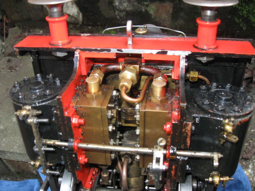 Had a great annual Rob Roy day at Andover last Sunday, they go really well once you get everything right.  |
|
|
|
Post by Deleted on Jun 18, 2014 11:55:02 GMT
Thank You for all the replies and info. I am gathering all I can.
Rex, Thank You for that brilliant pic ... that explains a bunch of stuff I was trying to figure out.
Roger, Thank You for that list of goodies to be aware of.
I got the steel for the frames yesterday and I will slowly get at both the Juliet2 and Rob Roy. I am trying to get a couple of other projects out of the way first as well as doing what "Her That Allows Me To Play" needs done in the garden.
I have joined a local club and spent most of last Sunday learning about lubrication, firing, watering and driving a loco. I did my first few solo runs as well ... It took 2 days to get the smile off my face. The pic is now my avitar ... it was the only way at the moment that I could add a pic. I will read up on that more.
Cheers,
Tom
|
|
|
|
Post by Deleted on Jun 18, 2014 14:02:34 GMT
Hi TOM---------well done that man !!..........It truly is a great feeling, isn't it ??---------Best of luck with your projects and please do post regularly on here??
|
|
|
|
Post by Deleted on Jun 18, 2014 14:08:05 GMT
well done tom... happy days ahead.. Pete |
|
|
|
Post by Deleted on Jun 18, 2014 21:53:53 GMT
Thank You very much folks. I appreciate all the help you have given me. I may have to buy some pints if we get "over there" next year. I haven't had a decent pint for over a year now.
Rex, if you ever get the chance, I would be interested in seeing a pic of the whole bottom of your engine.
I did a bit of cutting on the frames today, in between working on another project.
I am currently mainly working on a freelance Clishay/Goldbug/Tom Thumb. I am working on the engine part of it first. I had no idea there could be that many holes in a cylinder and it wouldn't fall apart.
Cheers,
Tom
|
|
|
|
Post by doubletop on Jun 19, 2014 9:56:42 GMT
On the subject of the Emma Victoria I was of the opinion that its a cut down Simplex, There are so many parts that are "Simplex like" Modifications to the Rob Roy, the bypass needs to be moved into the cab. Being on the front of the tank and having to lean forward to adjust it, when you can't see what you've set it to isn't very flash. For what its worth here's my thread on finishing off a Rob Roy, which may provide some ideas. I didn't build it though. www.homemodelenginemachinist.com/f31/rob-roy-8800/Pete |
|


