|
|
Post by Roger on Jul 23, 2014 6:47:41 GMT
When it comes to just the chassis Pete, I don't think it's a problem holding it by the buffer stocks. You can always add a register to locate on something a bit more manly if needs be. SPEEDY has those ghastly spigots that go through the buffer beam, so it's not a problem on there.
Whatever the device, I think you need something to make life easier. Turning my chassis over, I've got nothing to sit it on that won't damage the paint on the frames. I can't lay it on its side for the same reason. This is one of the drawbacks of painting things as you go.
I think Doug has it about right. Something is required to at least lift it up. Tipping it over a bit would certainly help.
When Alan kindly gained me access to the workshops at SVR, he showed me an arrangement they have there where a locomotive could be arranged to sit over a removable section of rail on one of the inspection pits. I suppose you could have a sturdy raised rail with as few supports as possible, and then have one or more sections that you could remove. That way you could leave it on its wheels and still remove an axle or have unobstructed access to the springs for example.
|
|
|
|
Post by Deleted on Jul 23, 2014 7:59:44 GMT
In Roger's picture there appears to be a wooden strut where the boiler would be. Do we think it is an essential part of the device or is it just an optical illusion? Peter ----------I think it's a tie bar to keep the two end plates in position when turning ??.........You can just see a screw and washer in that position on the L/H plate.....Because buffers tend to be used when handling a loco I recommend brazing them onto the buffer beam..........I have a Clarke hoist for lifting a loco onto the dismantling bench ( I believe ROGER has a similar set-up ?)..............That's a nice, simple idea that looks ok for a rolling chassis......I think a "variation on a theme" would be needed for a loco and boiler ??.... |
|
|
|
Post by Deleted on Jul 23, 2014 8:09:57 GMT
"Rolling Chassis" ?? ----------Oh dear, whatever next ??----------I'm in a GOOD MOOD this morning because the Route 66 Holiday people have agreed to a FULL REFUND on all monies paid = RESULT !!!!!!
|
|
jma1009
Elder Statesman

Posts: 5,901
|
Post by jma1009 on Jul 23, 2014 8:50:35 GMT
a couple of points spring to mind.
the first is that often there is a tendancy to add parts to a loco in the wrong order IMHO. i get the chassis fully completed 'full stop'. adjusting springing and connecting up pipe runs is then the only thing left to do that requires the completed loco to be accessed from underneath, usually. smokeboxes and boilers dont get added till much later. watch out for bolts from smokebox saddle into smokebox and avoid them at all possible using another method - running boards need removing and everything attached to them by that stage, plus also the cylinders if they are in the way on an outside cylindered loco!
secondly, buffer stocks are not always as strong as you might think. Roger has already noted how thin the buffer stocks are on his Speedy, and i wouldnt want to use the buffer stocks to support the weight of the loco. on Stepney and one of my other locos the buffer stocks are only attached by 4 off 8BA bolts each, and again i wouldnt want to lift the loco by the buffer stocks for fear of shearing the bolts!
thirdly, there is a lot to be said for breaking down the parts of the loco into sub assemblies that are attached to the rest of the loco in a non-prototype way. dont necessarily follow the drawings in this respect! martin evans regularly showed side tanks having as their base the loco running boards, and then the sides of the tanks also being cut out of sheet as one big part including the cab sides and bunker. if these parts are modified and split up into sub assemblies (with tanks having their own bases/bottoms) and cab and bunker separate then a lot of assembly difficulties are removed. one of the most difficult jobs in miniature is fitting and disconnecting the balance pipe between tanks if under the boiler. anything that can be done to make this simpler will save much gnashing of teeth and foul language later on!
(incidentally if anyone has an easy method for balance pipes that i can use for Stepney's tanks i would be very pleased to hear from them! there is no rear tank as per martin evans, just the side tanks for the water, plus of course the LBSCR wagon ive made)
another well known example is LBSC's PANSY with the check valves hidden by the pannier tanks as originally drawn. if anything goes wrong with the checkvalves (which invariably will happen if so inaccessible!) it is a huge job to remove the pannier tanks plus the balance pipe etc.
try and avoid adding nuts to bolts underneath running boards - tap the running boards instead say 10BA for bolts that attach splashers and anything else. trying to get nuts onto such bolts is one of the most frustrating things ever and even worse with the wheels in the way!
cheers,
julian
|
|
|
|
Post by ejparrott on Jul 23, 2014 9:21:41 GMT
I have seen a balance pipe used for side tanks which used a copper pipe between the two, passing under the boiler, the two ends had brass ferrules which had O ring grooves in them, they simply pushed in to brass sockets in the inside edges of the tanks sealed by the O ring, out of sight. It doesn't reach to the very bottom so doesn't balance the last 1/2" of water, but if that's all you've got left you're in trouble anyway!
|
|
jma1009
Elder Statesman
Posts: 5,901
|
Post by jma1009 on Jul 23, 2014 9:32:40 GMT
hi Ed,
that sounds an excellent method re balance pipes -if you (or anyone else who has used this method) can in due course provide a sketch or pics i would be very grateful.
cheers,
julian
|
|
|
|
Post by Roger on Jul 23, 2014 10:07:41 GMT
I made the buffer beams 4mm thick instead of the 1/8" and did the same for the frames so I'm sure they are strong enough. I've got four M3 screws plus a M12 fine bolt to hole the buffer stocks on and loads of bolts on angle brackets. Maybe some locomotives aren't built that strongly or are much heavier, and then I can see it being a problem.
I like the idea of breaking things down into more easily manageable units. I'm sure to have to take things apart from time to time so making it easy is appealing.
|
|
|
|
Post by drjohn on Jul 23, 2014 10:18:45 GMT
Hi Julian As I wanted to be able to remove all the superstructure without touching the boiler, I ran the balance pipe round the back of the cab with a take-off for the injector feed:-  DJ |
|
|
|
Post by Roger on Jul 23, 2014 11:28:03 GMT
Just a thought.... couldn't the bottom of the side tank just have a tapered spigot for the outlet, soldered to the bottom of the tank with a generous flange for support? That could mate with a piece attached to the frame on a bracket. That piece could just have a captive 'O' ring of ample cross section to accept the tapered pipe coming from the side tank. You wouldn't need any fittings, just lift the side tank and the connection would come free. If you don't have any nuts to unscrew or barbs to push hoses over, you don't need to have access to that area. You see that sort of assembly all the time on domestic appliances.
|
|
|
|
Post by ejparrott on Jul 23, 2014 11:44:06 GMT
exactly what I said....
I'll do you a drawing this afternoon Julian. I've a feeling it might have been Doug's Y4 or STD 4 I saw it on
|
|
|
|
Post by Doug on Jul 23, 2014 14:17:40 GMT
mine is pretty much the same as DJ's its across the cab and its horrible, it works fine but i dont like to see it on the cab floor, i will make speedy's hidden under the boiler (its not shown on the plans) Juian I am with you 100% the more you can attach/remove without disturbing something else the better.
|
|
|
|
Post by Doug on Jul 23, 2014 14:19:43 GMT
exactly what I said.... I'll do you a drawing this afternoon Julian. I've a feeling it might have been Doug's Y4 or STD 4 I saw it on i would be quite interested to see that too Ed  great idea. |
|
|
|
Post by ejparrott on Jul 23, 2014 22:42:52 GMT
Too busy tonight, I'll do it in the morning and load it to photobucket, then I can post it here.
|
|
|
|
Post by drjohn on Jul 24, 2014 2:39:41 GMT
Just a thought.... couldn't the bottom of the side tank just have a tapered spigot for the outlet, soldered to the bottom of the tank with a generous flange for support? That could mate with a piece attached to the frame on a bracket. That piece could just have a captive 'O' ring of ample cross section to accept the tapered pipe coming from the side tank. You wouldn't need any fittings, just lift the side tank and the connection would come free. If you don't have any nuts to unscrew or barbs to push hoses over, you don't need to have access to that area. You see that sort of assembly all the time on domestic appliances. Just a thought Roger - instead of pontificating, show us pictures. Acerbism creeping in again! DJ And while I'm at it, what's all this about soldering things into the bottom of the tanks for mounting. What's wrong with bolt nut and washers and a bit of gasket material - and how are you going to mount the hand pump in the tank? |
|
|
|
Post by drjohn on Jul 24, 2014 6:13:59 GMT
És back --
Whenever I see Roger I am always reminded of ---
There was a young lady called Maud
Who thought she'd been visited by God
But it wasn't the almighty
Who lifted her nighty
Twas Roger the bodger the sod!
Lol
|
|
|
|
Post by Roger on Jul 24, 2014 6:26:24 GMT
Just a thought.... couldn't the bottom of the side tank just have a tapered spigot for the outlet, soldered to the bottom of the tank with a generous flange for support? That could mate with a piece attached to the frame on a bracket. That piece could just have a captive 'O' ring of ample cross section to accept the tapered pipe coming from the side tank. You wouldn't need any fittings, just lift the side tank and the connection would come free. If you don't have any nuts to unscrew or barbs to push hoses over, you don't need to have access to that area. You see that sort of assembly all the time on domestic appliances. Just a thought Roger - instead of pontificating, show us pictures. Acerbism creeping in again! DJ And while I'm at it, what's all this about soldering things into the bottom of the tanks for mounting. What's wrong with bolt nut and washers and a bit of gasket material - and how are you going to mount the hand pump in the tank? I thought it was a useful idea worth sharing, I don't have pictures. In any case, a few words describe it well enough, it's a simple idea. Anyone can look up the manufacturers suggested percentage compression on an 'O' ring and the rest would have to suit the tank. If I do it that way, I'll post pictures then. I think from the number of post here about leaking tenders for example, that leaking is an issue. The fewer holes in a container the better in my view. I've never built a locomotive so what would I know anyway. Gaskets and nuts and bolts are fine if you've got a rigid structure to seal that way. I'm not sure that's the case with the thin walls of tanks and tenders. If these things need to come off for a strip down, it's going to be a lot easier if those joints don't have to be split and re-sealed. People can make these things however they like, I really don't care. I like an easy life, so I often do things differently to the norm. That seems to upset some people for some reason I can't fathom. I don't intend to fit a hand pump in the side tank where it's inaccessible. I probably won't have one at all. |
|
jma1009
Elder Statesman
Posts: 5,901
|
Post by jma1009 on Jul 24, 2014 7:27:47 GMT
hi roger,
dont worry about Dr John! he is ultra critical and acerbic - on one of his good days he's worse than me on one of my bad days, and we are well used to his ways on here! he has built a rather nice Simplex with some ingenious touches.
dr john, unfortunately the arrangement of balance pipes on your Simplex would be fine on my Stepney were it not for the rear wheels and cab boxes being in the way and preventing such an arrangement. also an 'underneath the tanks' arrangement that ive used before is not possible due to the position of the driving wheels and high position of the inside valvegear and position of the weighshaft arms.
LINDA's balance pipes for the saddle tank have banjo connections but to give an adequate throughway the banjo bolts are made of very tough ali bronze. i can remove the saddle tank, cab and boiler off LINDA in 15 minutes without having to tilt or lift up the loco to access anything. the boiler slides out of the rear of the smokebox, the smokebox being integral with the frames and cylinders. my GWR KING however takes a good 2 days with the use of many special tools and will only come apart one way and a set proceedure has to be followed and it is an awful job which during it's long awaited overhaul i will try and simplify.
cheers,
julian
|
|
|
|
Post by ejparrott on Jul 24, 2014 7:41:35 GMT
|
|
jma1009
Elder Statesman
Posts: 5,901
|
Post by jma1009 on Jul 24, 2014 7:44:19 GMT
thank you Ed,
that's excellent. many thanks for taking the trouble to draw same. very much appreciated and very helpful!
cheers,
julian
|
|
|
|
Post by ejparrott on Jul 24, 2014 7:50:06 GMT
Don't know if this might show better.... 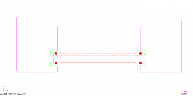 blue I find great for doing the CAD against, not so good for screen shots. The balance pipe just has two ferrules soldered on the end with 2 o ring grooves, then the tank has the two bushes. The important thing is not to end up in a situation where the pipe could work its way right through in to one tank. On this example the step on the inside of the bush would prevent that, and the tube should be about 1/16" shorter than the gap so it can expand if it want's to, and so that it doesn't place any load on the tank sides. Alternativly, the bush in the tank side can be a plain tophat through bush, and to stop the pipe sliding through it should have a head turned behind the O ring. Again, measured up so that it's shy and deosn't load the tank. All dimensions to be taken from the engine and designed to suit, no point me dimensioning anything. The balance pipe should be as large as possible, as low as possible, and ideally complete with a drain tap. |
|


 great idea.
