|
|
Post by Roger on Oct 10, 2014 19:04:57 GMT
I don't see how you can rectify a single phase input and get 650VDC, something else is going on. Didn't you say it was a special drive with a booster to get the high DC internal Bus?
Anyway, the main thing is that you have a working drive, this it great news.
|
|
bhk
Part of the e-furniture

Posts: 458 
|
Post by bhk on Oct 10, 2014 19:21:37 GMT
You will never get a meaningful voltage reading. Meters are designed to read a sine wave, the output from an inverter is more like a square wave but with the on time and the off time varied with respect to each other (PWM or Pulse Width Modulation) Andy that is the point of the analog meter, it's not trying to read it, it's just reads to the peak voltage. You can with maths calculate you true voltage from your peak voltage. What I've done is circumnavigated that by using my digital meter to read what it thinks is DC. It's a close enough reading to get an idea of voltage. Fluke do sell a meter capable of reading it correctly with a referencing probe. |
|
bhk
Part of the e-furniture
Posts: 458
|
Post by bhk on Oct 10, 2014 19:22:40 GMT
I don't see how you can rectify a single phase input and get 650VDC, something else is going on. Didn't you say it was a special drive with a booster to get the high DC internal Bus? Anyway, the main thing is that you have a working drive, this it great news. Rodger, it Wikipedia but does give the basics of the principle en.m.wikipedia.org/wiki/Voltage_multiplier |
|
|
|
Post by andyhigham on Oct 10, 2014 19:28:08 GMT
I have just scrolled through the diagnostic parameters on my inverter. The DC link voltage is 330V which ties in with rectified 230v with a capacitor (sqr root 2) x AC volts
|
|
|
|
Post by andyhigham on Oct 10, 2014 19:43:49 GMT
Using voltage multipliers is a non starter in an inverter, the current would be almost zero.
To get a higher voltage a step up input transformer could be used but say at 2.2Kw, it would be a big lump and weigh about 25KG
|
|
bhk
Part of the e-furniture
Posts: 458
|
Post by bhk on Oct 10, 2014 20:06:03 GMT
Using voltage multipliers is a non starter in an inverter, the current would be almost zero. To get a higher voltage a step up input transformer could be used but say at 2.2Kw, it would be a big lump and weigh about 25KG Andy without ripping my unit apart I can't tell you what components are in there, but I know it's not a transformer. It only weights 2kg and that these step up inverters are of common place using voltage multiplier / double voltage rectifiers. |
|
|
|
Post by Roger on Oct 10, 2014 21:30:16 GMT
Go on, take it to bits, we want to see what's inside....  |
|
steam4ian
Elder Statesman
 One good turn deserves another
Posts: 2,069
|
Post by steam4ian on Oct 10, 2014 22:54:00 GMT
Sean
You didn't tell us if you got a new motor wound for 240 volts not 415V?
Did you get the control switch and contactor sorted?
I disagree with Andy regarding the voltage doubler, his statement is not consistent with my experience.
The Wikipedia article might be confusing because it only shows half wave voltage multipliers. The full wave version is just like a full wave bridge rectifier but with two of the diodes replaced by capacitors.
Ian
|
|
bhk
Part of the e-furniture
Posts: 458
|
Post by bhk on Oct 12, 2014 0:53:59 GMT
Well took my first cut with lathe today, all be it with a temporary install of the electrics. Wanted to gauge it for trueness. I got .02mm taper over 50mm, it's a lot!! but the machines not been levelled or bolted down. This will be done when we move house next year.
I'm using the original motor, on the low speed windings ie: 4 pole, this gives me a range of 19rpm @ 30hrtz to 2000rpm @ 130hrtz
Now before people start saying I should not run the motor at 120hrtz, what's is important to remember is that the motor is rated up to that rpm, but would normally require a pole shift (high speed 2 pole windings) to achieve it.
I have allowed a little over the rated speed to give me a slighter higher top speed.
Once the bits I'm waiting for arrive my setup will be as follows.
A switch box mounted above the headstock with an emergency stop, fault indication light and potentiometer for speed control.
The emergency stop runs a contactor on the supply side to cut power to the drive. Thanks to Ian for this idea.
Fwd/rev/stop are all off the apron.
I got the drive to coast to a stop rather than the drive braking it, this is so that I can still use the foot brake, I think its essential on a non clutched machine for screw cutting.
|
|
steam4ian
Elder Statesman
One good turn deserves another
Posts: 2,069
|
Post by steam4ian on Oct 12, 2014 2:50:11 GMT
Sean
Well done.
Was that taper from turning between centres, I guess not and that you were using the 3 jaw chuck.
Regards
Ian
|
|
bhk
Part of the e-furniture
Posts: 458
|
Post by bhk on Oct 12, 2014 4:43:13 GMT
Sean Well done. Was that taper from turning between centres, I guess not and that you were using the 3 jaw chuck. Regards Ian Hi Ian, Yes that's correct, I'm not worried about it till the machines in its final home. Then I'll see how it cuts and align the headstock if needed, though I hope it's just a case of levelling. |
|
|
|
Post by runner42 on Oct 12, 2014 6:53:58 GMT
Well took my first cut with lathe today, all be it with a temporary install of the electrics. Wanted to gauge it for trueness. I got .02mm taper over 50mm, it's a lot!! but the machines not been levelled or bolted down. This will be done when we move house next year. When I read you are concerned about .02mm taper over 50mm I thought what league does this level of accuracy belong to? I could even measure with any repeatability to that level even if I had the requisite accurate measuring instrument. What accuracy are you hoping to achieve with everything set-up? Anyway congratulations of obtaining a fine machine. Brian |
|
|
|
Post by ejparrott on Oct 12, 2014 8:13:52 GMT
.02 over 50mm otherwise translates as 1thou over 2", much more than it should be. The one at work is gettinga bit worn now, that's showing about a thou over 6".
|
|
|
|
Post by Roger on Oct 12, 2014 8:35:59 GMT
I'm not surprised at that error, it's not large for a machine that isn't bolted down. You'll easily improve on that and when you start adjusting it, you'll be amazed at just how flexible the machine bed is!
Personally I don't see much value in a foot brake except for when you want to hold the chuck still. Screw cutting is usually done as low speeds and even if it's long and you want to get on with it, you now have the luxury of slowing it right down as you approach the end. The foot brake could open the emergency stop circuit so you could still use it with decel on the drive. I think you'll find the slow stopping an irritation, but you'll soon decide if that's the case or not.
Anyway, that's another milestone and a great result.
|
|
bhk
Part of the e-furniture
Posts: 458
|
Post by bhk on Oct 12, 2014 8:59:05 GMT
I'll be happy if once it's bolted down and levelled it keeps a thou over 6 inches, I can work with that. But for now at least I know what its doing and can work around it.
Roger I think it's all preferences when it comes to it.
I've currently got the machine ramping up over 10 seconds I may reduce this once I get round to measuring starting current draw in each gear, it's stops instantly on the foot brake if I want it too or can let it run down, being a gear driven machine there is plenty of resistance to act as a natural brake.
|
|
|
|
Post by Roger on Oct 12, 2014 9:13:56 GMT
You can probably get it closer if you want to try just by sticking a piece of sheet metal under one of the fixing points and using its own weight. As you say, it's something you can live with. It think 10 seconds is on the long side and I think you'll find that the current draw is low. Contrast that to turning on the lathe with a 3-phase supply!
|
|
44767
Statesman
Posts: 529
|
Post by 44767 on Oct 12, 2014 12:53:24 GMT
Hi Sean, a great lathe you found! I'm a bit late coming in on this thread but for what it's worth I was in a similar situation when I bought my first machine- a Weiler LZ330. It had a 3 phase motor which of course I had to change. I worked out that I could use the apron switch to change the starter windings to give forward and reverse and until I had 3 phase I just lived with the fact that the starter windings have to drop back in before it can change direction. It really was only a problem with metric threads.
The original motor is in again now but since it is DOL 3 HP it always started with quite a shunt on the gearbox. I bought a Allen-Bradley soft start for it. Although it appears to start instantly, it ramps up to speed over 0.5 sec. It is adjustable for the time to ramp up and for the current it draws doing so. Therefore I can chuck it from forwards to reverse without fear of overloading anything.
I'll have to come around when I'm back to see your new toy!
Mike
|
|
bhk
Part of the e-furniture
Posts: 458
|
Post by bhk on Oct 13, 2014 3:38:15 GMT
Hi Sean, a great lathe you found! I'm a bit late coming in on this thread but for what it's worth I was in a similar situation when I bought my first machine- a Weiler LZ330. It had a 3 phase motor which of course I had to change. I worked out that I could use the apron switch to change the starter windings to give forward and reverse and until I had 3 phase I just lived with the fact that the starter windings have to drop back in before it can change direction. It really was only a problem with metric threads. The original motor is in again now but since it is DOL 3 HP it always started with quite a shunt on the gearbox. I bought a Allen-Bradley soft start for it. Although it appears to start instantly, it ramps up to speed over 0.5 sec. It is adjustable for the time to ramp up and for the current it draws doing so. Therefore I can chuck it from forwards to reverse without fear of overloading anything. I'll have to come around when I'm back to see your new toy! Mike Shame I can't bring it to a meet. Welcome to pop round. I should have some shinny parts by then, decided to start on a 5" gauge v1 Tank (an engine I've always liked), I've got a set of casting at a very good price. I've ordered a set of Doug hewson wagon drawings to build a driving truck. Its a bit more manageable and interesting than the sweet William, I'm sure all will agree. I've got a friend who is going to lend me a clamp meter so I can finish setting up the drive (bit safer than running my meter inline) Cheers Sean |
|
bhk
Part of the e-furniture
Posts: 458
|
Post by bhk on Oct 24, 2014 10:02:04 GMT
Slowly but surely getting there, Had a few spare hours to get into the garage tonight. I wanted to lay out the switches so I could decide what size enclosure to buy to house it. 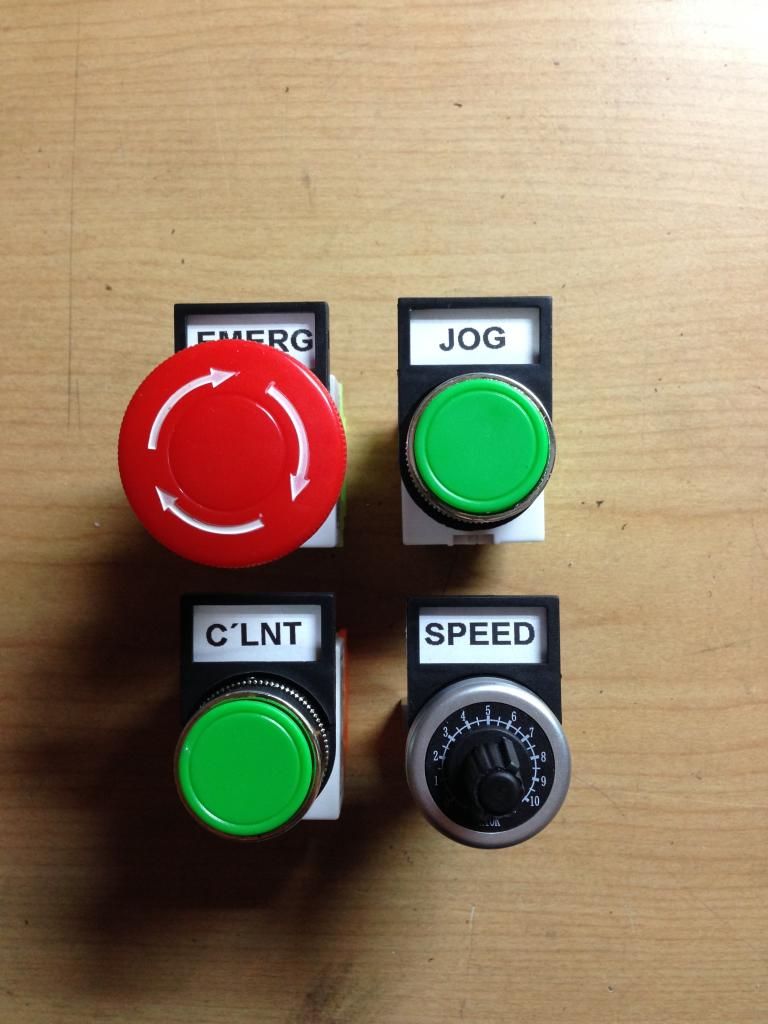 This is the layout I've come out with, I had to hunt around to get some multi core cable to make up a control lead, managed to get an off cut of 18 core (that allows expansion of functions in the future if I wish, like the idea of a spindle RPM readout) at a reasonable price, though it is 2.5mm section so it's a weighty bit of cable. I also wanted to measure up and start to think about the layout for enclosure to house the inverter. I had a box lid which is exactly the same size of the enclosure I was thinking about it. 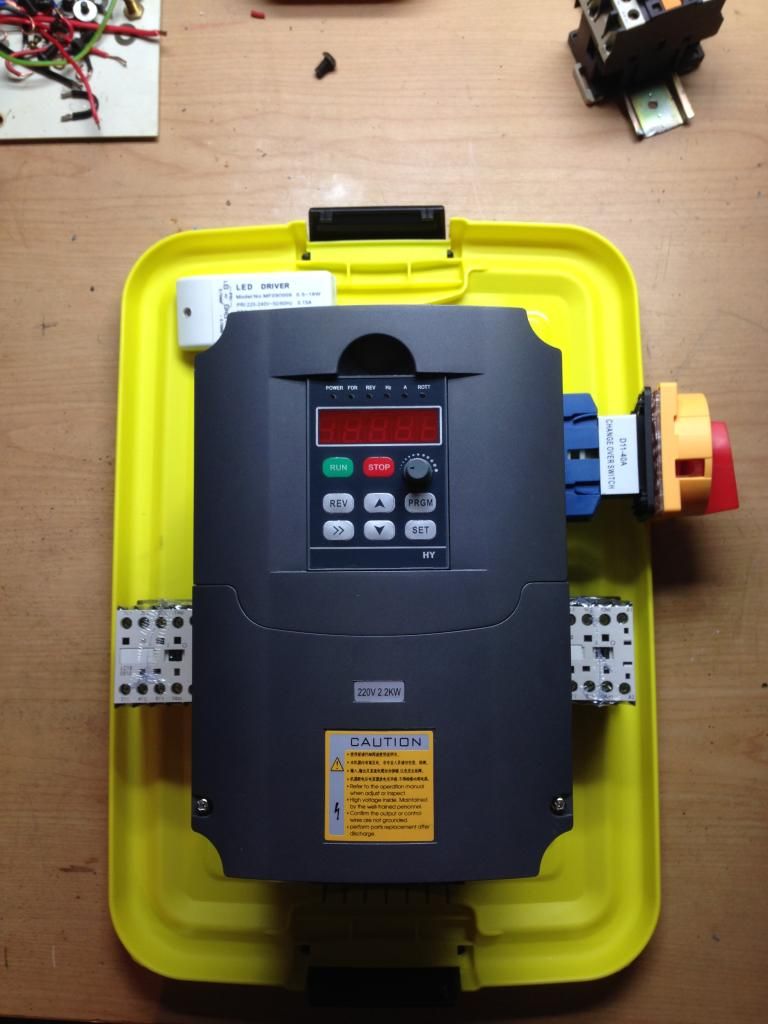 So now I can order the two boxes (last of the required parts) and get it finished up. Cheers Sean |
|
|
|
Post by Roger on Oct 24, 2014 16:55:09 GMT
So is that a push/push type switch for the coolant then?
|
|