|
|
Post by Cro on Oct 8, 2014 18:56:21 GMT
Hey everyone, I recently decided to take on the challenge of building an LNER V2 in 5"....well actually the plan is too do 3 of them but that's another story. About me, I am currently studying for my degree in Electrical and Electronic Engineering at Brunel University and just started my 5th and final year here. I have been involved in model engineering for 15 years now since the age of 8 taking on what my Grandfather started many many years ago and currently just finishing off a Winson 9f that if anyone knows me will confirm that it is far from a winson model anymore with a moderate level of detail. I got hold of a set of the Micheal Breeze drawings for the V2 but decided I wasn't overly keen on the set up of the cylinders being moved from their original position so decided I would firstly set about moving them back into line but this has now developed into me building the original monobloc casting. The best way for this is through the use of CAD and so the plan is to design and build in CAD the full loco to the Nth degree using a combination of works drawings and Breeze drawings and by the time I have finished this I hope to have all of my other projects out the way so I can focus on these. The loco will be based on 'Green Arrow' 4771 at York as it is accessible for me to get info/photos and so on. Basically this is so I can post updates of the CAD modelling as it goes along and for people to share any info or tips they may have or ask any questions. The photos here show the current progress on the Monobloc as it went along and these are done from the works drawings and modeled in full size, this is around 50/55 hours worth of modelling so far and I will then go onto the frames from here. 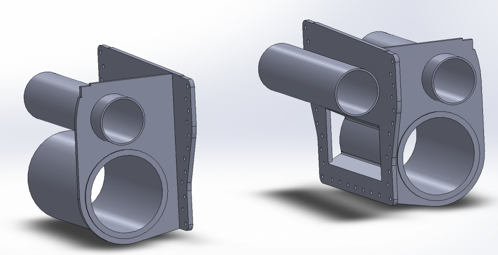 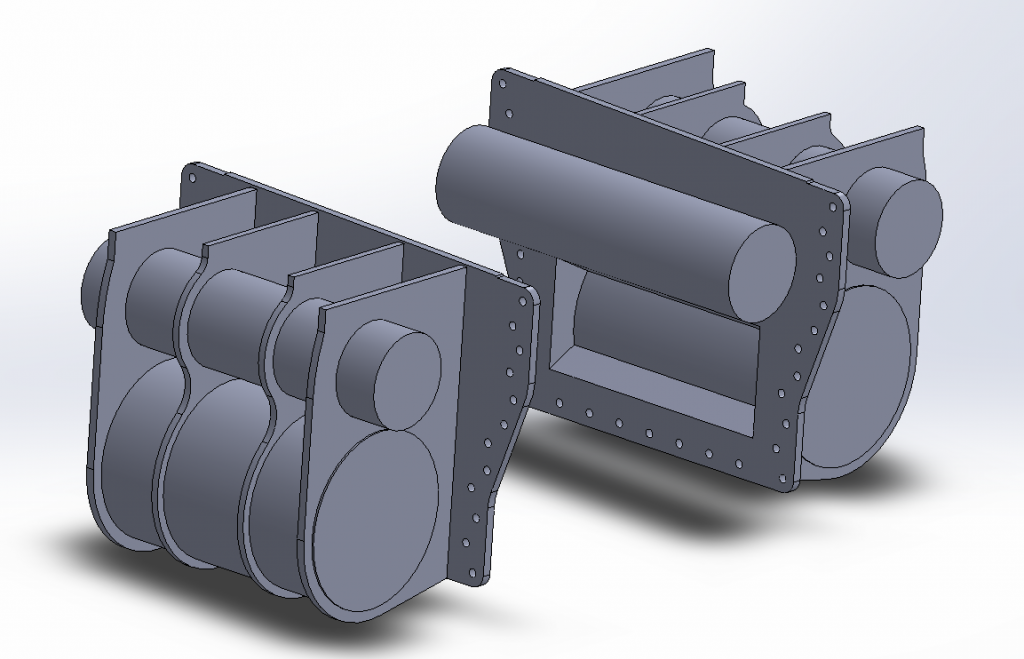 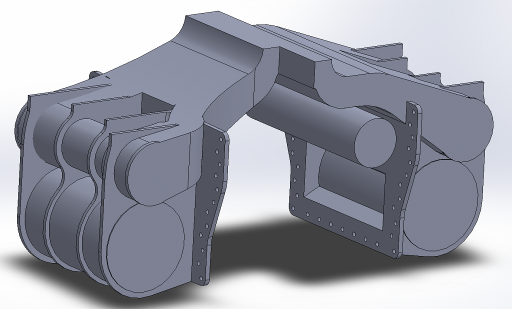 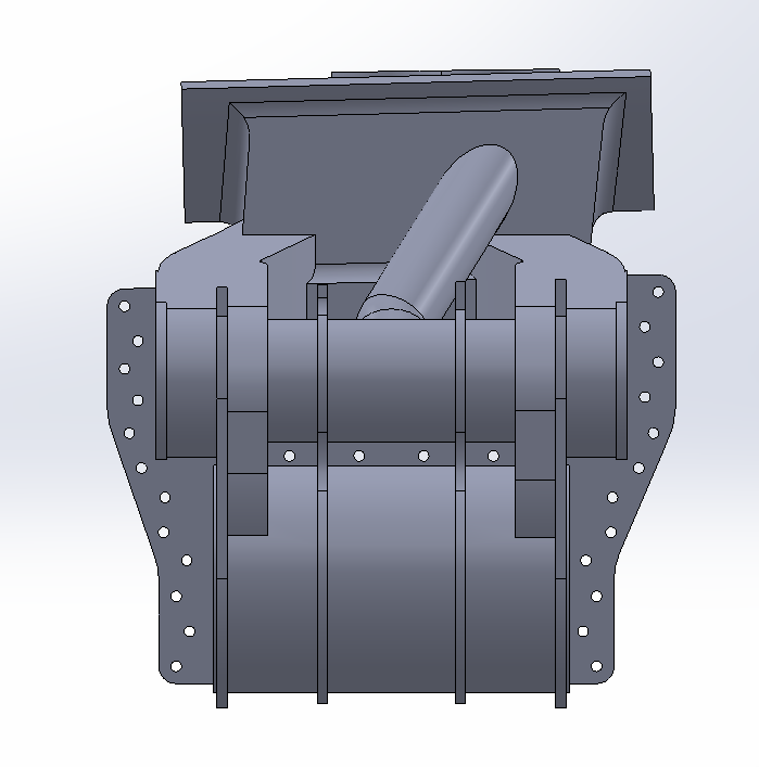 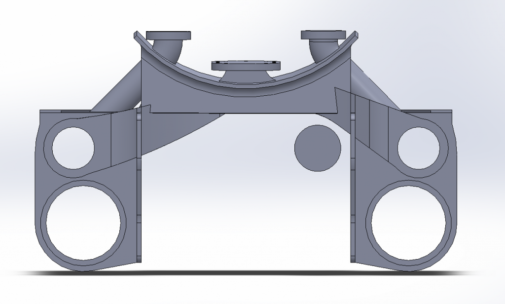 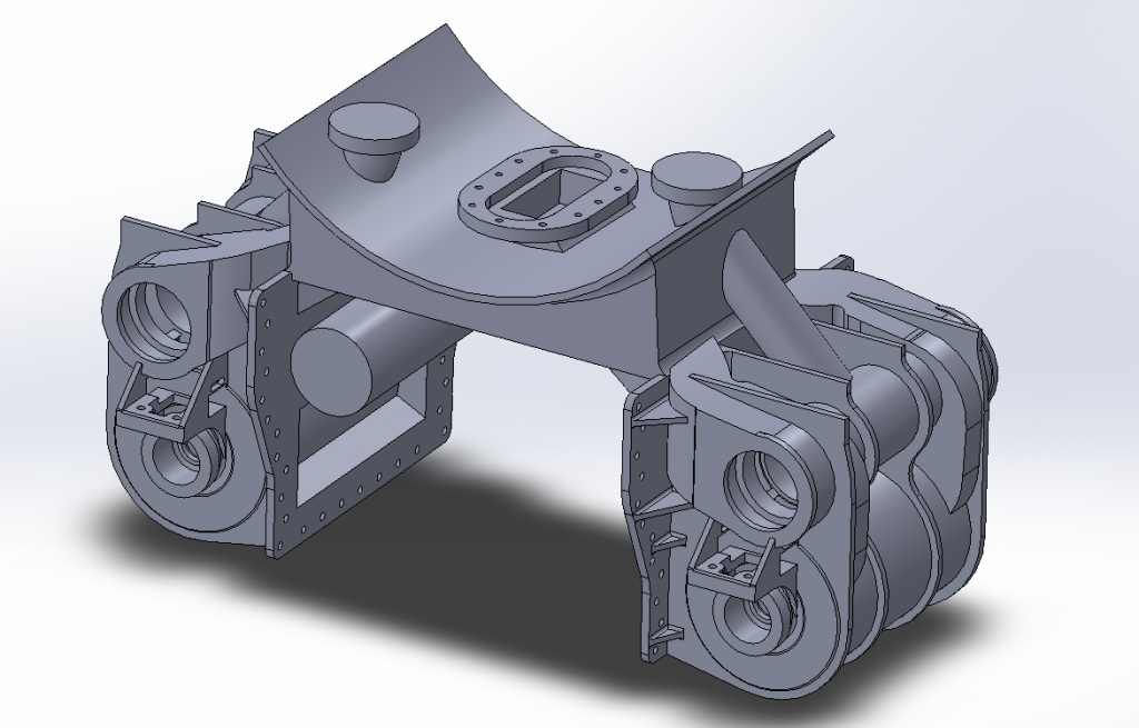
I am also currently doing many other CAD models for scale items such as washout plugs, mud hole covers and the latest is a working LMS Vac/Steam Brake valve so plenty to keep me busy! Please feel free to comment, ask question or give any info. I know many will have seen Ben's great work on his V2 already and its great to see so much support. Cheers, Cro |
|
|
|
Post by Deleted on Oct 8, 2014 20:21:56 GMT
Hey Adam!
Welcome! About time you got on here!
Great to see the progress is still ongoing with the block, would be good to see some of the 9f too.....
Anyway enjoy it here, there is a wealth of knowledge to be tapped!
Cheers
Ben
|
|
|
|
Post by Cro on Oct 8, 2014 21:01:42 GMT
Cheers Ben,
This is another great place to share info and get some great feedback!
Will add some photos of the 9f later on but you need to get back to the workshop and crack on!
Cheers,
Cro
|
|
|
|
Post by silverfox on Oct 9, 2014 16:28:06 GMT
Steady on Lads this COULD be HippyEmma!!!!!
|
|
|
|
Post by Deleted on Oct 9, 2014 17:23:42 GMT
It's not, I know Adam personally
|
|
bhk
Part of the e-furniture

Posts: 458 
|
Post by bhk on Oct 9, 2014 17:31:48 GMT
Hi Adam, really nice work is going to be a superb step up in detail once cast to that presently available. This is what I love about modern techniques, it's going to take models being made to the next level
Cheers
Sean
|
|
|
|
Post by Cro on Oct 9, 2014 18:38:02 GMT
Sean,
Thanks, I hope to use modern technology as much as possible with this project to make it just right, I love doing the work in the workshop myself and saying "I've done that" but I also believe in using the technology that is evolving around us to make amazing bits of kit!
Cheers,
Cro
|
|
|
|
Post by silverfox on Oct 9, 2014 21:09:07 GMT
Ben
It was said in jest!! Esp as there is a mention of being on a course
Nice drawings as well
Ron
|
|
|
|
Post by Cro on Oct 15, 2014 22:03:23 GMT
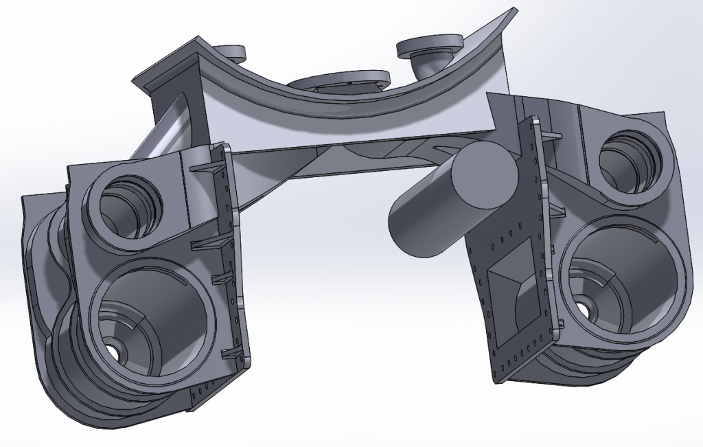
Bit of progress this evening away from the dissertation. Center cylinder in place with inlet chambers in and exhaust passages shaped out. 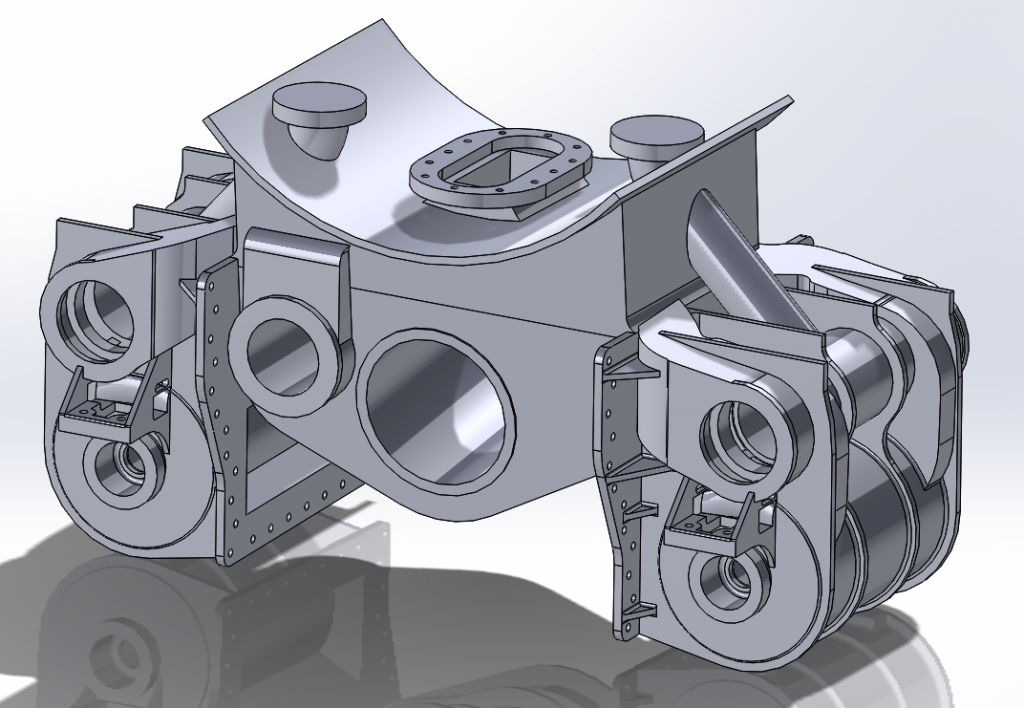 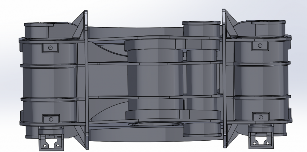 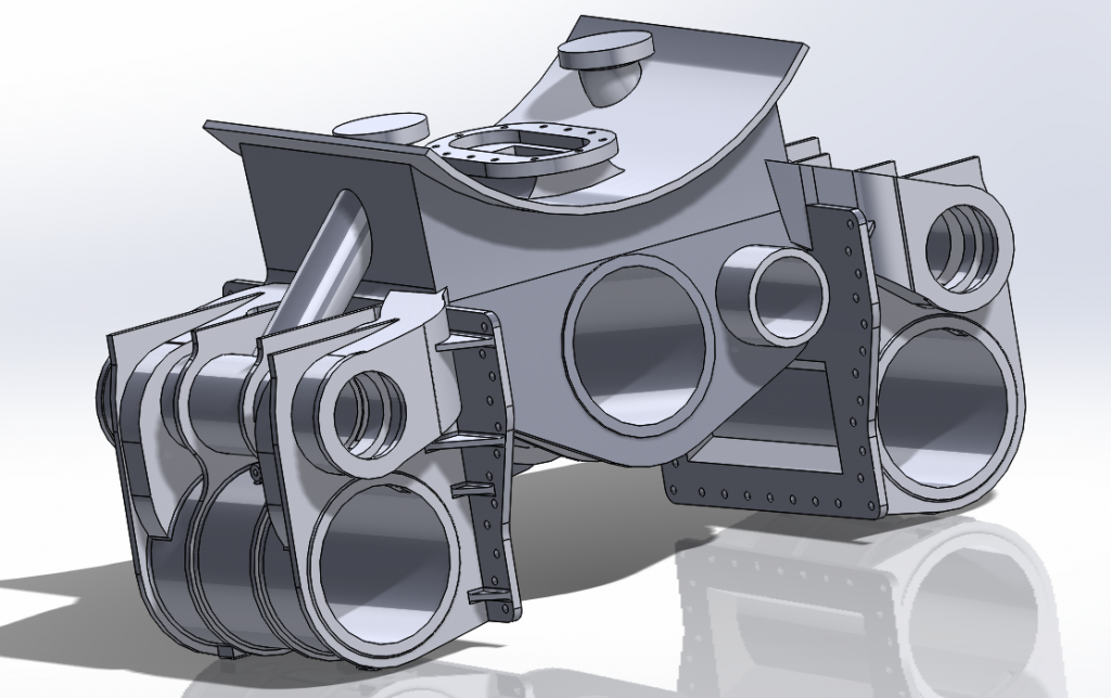 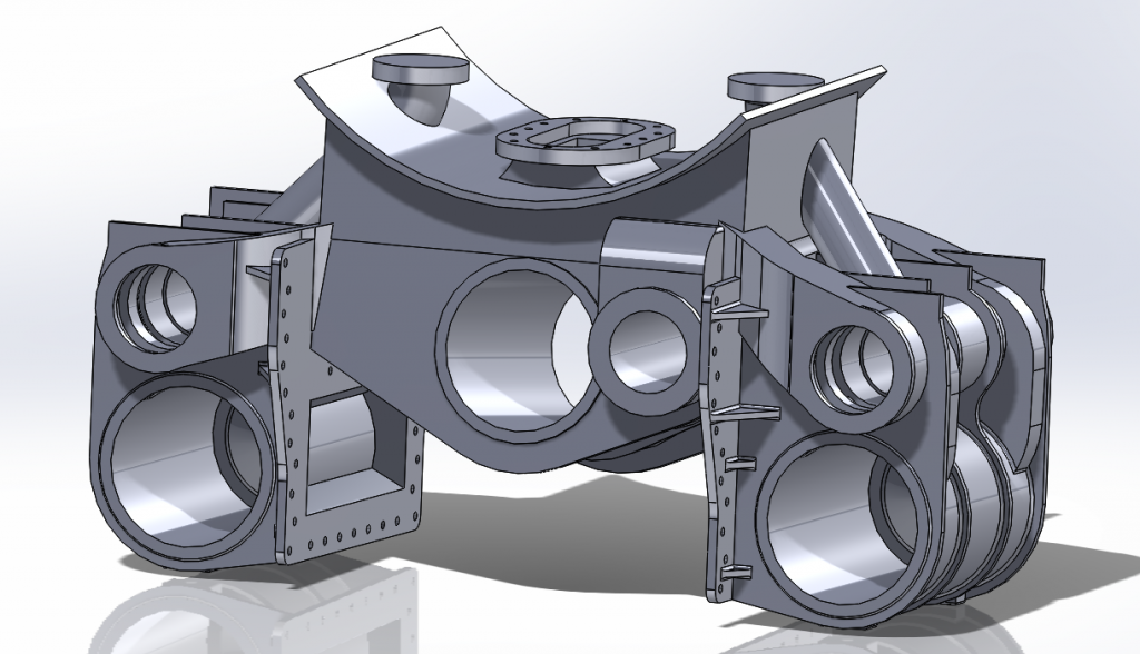 Won't be too long before the model is complete and can be scaled down, then onto the chassis. Hope you like, Cro |
|
44767
Statesman
Posts: 529
|
Post by 44767 on Oct 16, 2014 2:21:33 GMT
Really nice work Adam. A man after my own heart! This really is one area of our hobby which is really taking off. It stands to reason that with the younger modellers, who were brought up using computers, coming through that this is model engineering's future. I find it fascinating while working from the works drawings. It's all the background information one gleans as to why things were done certain ways etc.
A great start and I look forward to following your build.
Mike
|
|
|
|
Post by Cro on Feb 27, 2015 1:32:58 GMT
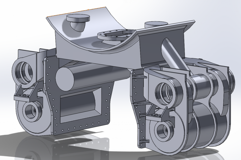
So been quite a while since I did an update on this, its one of those projects that will go long periods with a gap and with everything else I have taken on this one gets done now and then but away from the BR fittings for an evening I had time to go back and make a few changes since learning things in the last 4 months. As most know now I love my CAD modelling and whilst at uni I have no access to the workshop I am making the most of my time for when I can get back in there and get working on these bits. The main 2 changes on this since I basically finished the majority of the model are the exhaust passages and the filleting of the edges. I was never happy with the "lofted cut" I did for the passages, they created thin edges in strange places and never really followed a good profile so I adopted a different method for this keeping it on a fixed sketch plane rather than a 3D sketch plane, which is just a nightmare to work with, and also cutting away the are under the blast pipe in a separate way to reduce the length of the loft as this could be done also on a fixed plane. So here is how they turned out. 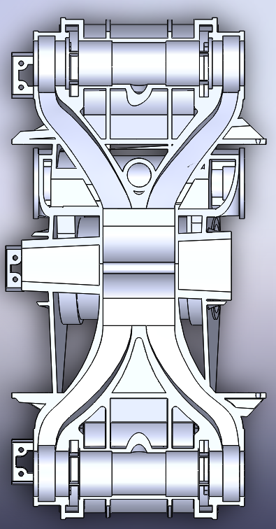 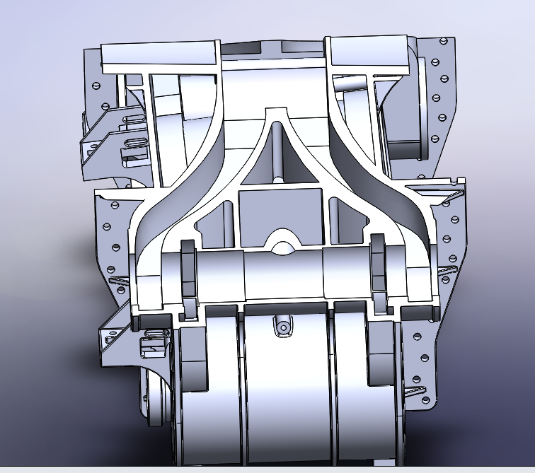 I also spent a little bit of time with the GA and my V2 book modelling the valve guides, not quite 100% right yet as some bits are very hard to take from the GA so will have to wait on the official drawing to get it just right. 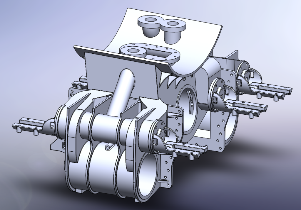 Pete I think these could suit your loco, more likely the rear valve guides but haven't had a look yet. Just waiting on a bunch of drawings now for the frames and so on and then I can start on those, for now back to the filleting and more BR fittings! next few weeks should be exciting there as castings start to arrive! Cheers, Adam |
|
|
|
Post by Deleted on Feb 27, 2015 9:56:36 GMT
Hi Adam...that looks very good...most impressive....I only wish that you had started 10 years ago with Gresley's A1/3...  It goes without saying that any parts you make that are Compatible with the A1/3 and if I haven't already made them for myself would be of great interest to me. Cheers Pete |
|
|
|
Post by Cro on Feb 27, 2015 10:26:33 GMT
Pete,
Not sure at 12 I had the skill set required for this! Hopefully some parts will coinside though if you ever need any!
Adam
|
|
|
|
Post by silverfox on Feb 28, 2015 0:11:58 GMT
Adam, They look really great. I only wish i could even start on getting a 2D prog running, let alonewhat you have done. congratulations.
I am pulling my hair out at the moment trying to get the outer expansion link brackets in pencil before i attempt the programme.
Just cant seem to get the correct location of the centre for the radius at the trunnion end as Malcolm hasnt got any measurements
on it, and i am drawing 2X to make it a bit clearer.
There could well be some common parts on the B17...........
Looking forward to your updates
Ron
|
|
|
|
Post by Cro on Feb 28, 2015 0:26:49 GMT
Cheers Ron,
It's very satisfying doing the modelling like this although the later stages such as the filleting and so on really get your head spinning.
There may well be some common parts so if you see any as it progresses then just shout!
The wonderful thing about drawing these parts and shapes is you can play around with them and adjust dimensions and see how it will look after where as a pen and paper is a little bit limited in that respect.
Adam
|
|
|
|
Post by runner42 on Feb 28, 2015 5:36:20 GMT
Hi Adam,
I am marvelling at your ability to translate I assume a drawing into a 3D CAD model, which I again assume is going to result in a 3D printed casting. Very precise and close to detail but no matter how close the casting is you will have to do some machining of the cylinder bores and piston valve bores and liners, I therefore am curious is to how much allowance you make for machining? Will you also apply the same principle to say the pistons or is there not much mileage in doing them this way? By the way what 3D CAD program do you use?
Like others I wish that I could master the 3D CAD program and produce the output that you are able.
Brian
PS Will the cylinders require machining at the ends so that the cylinder covers are flush and if so will this produce problems in accessing the ends for machining? PPS On reflection I think many faces need to be machined, did you consider a machining plan when developing the model?
|
|
|
|
Post by Cro on Feb 28, 2015 17:53:25 GMT
Brian, As you point out there are a lot of faces that will need machining, the main to consider are the two mounting faces for the frames and the 3 piston bores and both ends of the valve bores. my plan will be to get a test print done to see how it looks once printed so I can get an idea of how it can be machined best and that may produce a plan. Machining allowances will be down to how well it can be cast, so far I have found things to be very accurate so I imagine I can get away with a very small amount for this. I have a feeling I may end up fitting liners to the piston bores anyway but I need to look into this a bit more nearer the time. Here is the drawing of the Cylinder bloc I have been working from so you have an idea of what its been like. 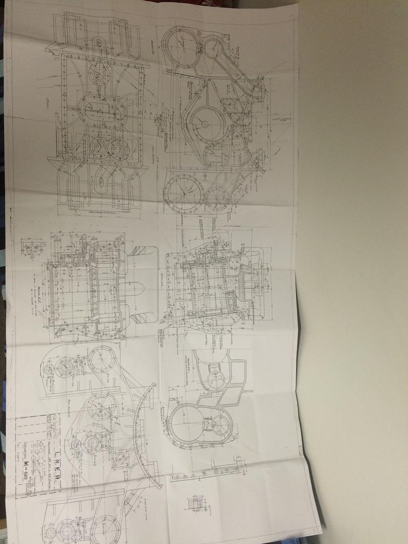 |
|
|
|
Post by Cro on May 5, 2015 8:58:46 GMT
So some inspiration hit me over the weekend and I decided to jump back on this last night. Main thing for me now the cylinders are mostly done is the frames, once these are together its a case of doing the motion work and then scaling down and adjusting to get set up in the best way possible. So on with the frames, final job I had left to do on these was to bend the rear section inwards. 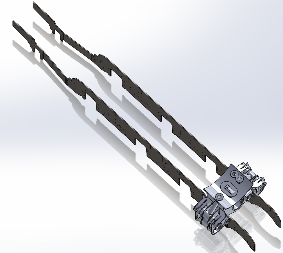 This is created as a sheet metal part in CAD which means that when I "flatten" the part the bend allowances are taken into account. Something to hold the rear of the frames together is the dragbox, so I have started on that, about 80% done here. 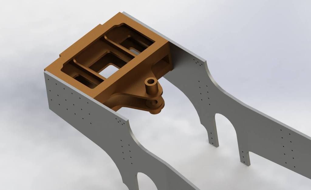 Something a little different and actually quite complicated to model in 3D is the chimney. This is done with a sweep with 6 guide lines and defining sketch. To achieve the sweep around the smokebox shape the sketch lines need to be on a 3D place allowing them to rotate around the shape but also change the plane they are on. Here is this sketch before performing the sweep. 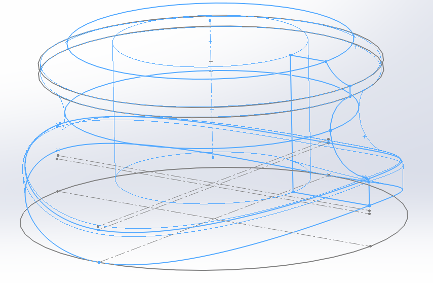 And the final chimney after performing a cut through to "machine" the final radius of the smokebox. 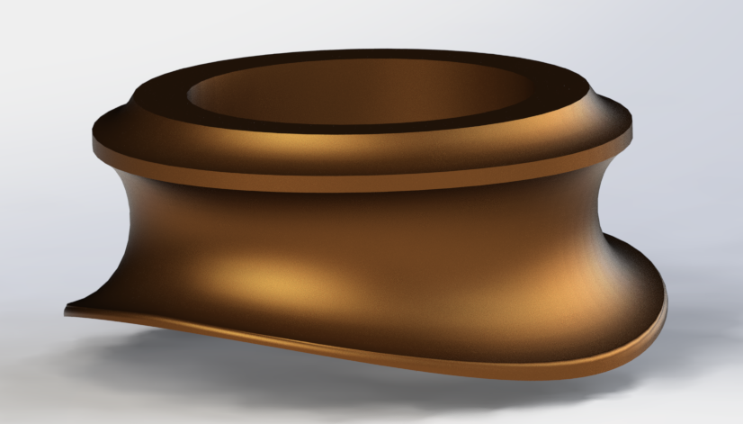 Cheers, Adam |
|
|
|
Post by Donald G on May 5, 2015 14:34:45 GMT
Adam
That is just outstanding work. I cab 2D CAD, but have tried 3D with little or no success. Keep up the brilliant work.
Donald
|
|
|
|
Post by Cro on May 5, 2015 15:38:24 GMT
Adam That is just outstanding work. I cab 2D CAD, but have tried 3D with little or no success. Keep up the brilliant work. Donald Donald, thanks for the support, I find it ok, it can be a struggle at time but things like this dragbox are fairly simple as everything is pretty much square there are no complicated angles or cuts and is a great practice piece for anyone trying to learn it. Adam |
|


 It goes without saying that any parts you make that are Compatible with the A1/3 and if I haven't already made them for myself would be of great interest to me.


