|
|
Post by Roger on Nov 3, 2014 14:26:40 GMT
When I get a minute, I'll check the difference in the bush position, it's not much. There's going to be an easy work round for that. Don't assume that the gear frame is going to be in the same place either, the expansion link clashes with it. I'll send you some drawings of what I think is right if you let me have your email, I can't remember if I've got that.
I think the fixture would fit your axleboxes, I've only Metricated the Imerial dimensions without much rounding on most features. If you needed to ease something then that's no a big issue, I'm not likely to need it again anyway and I expect it would still work for mine even then.
|
|
|
|
Post by Rob on Nov 3, 2014 19:23:50 GMT
You should have my e-mail Roger, if it's not still stored in your mail client it'll be one of the older PMs!
|
|
|
|
Post by Roger on Nov 3, 2014 20:33:13 GMT
No problem, I email to so many different people I lose the thread of then.... old age is creeping in...
|
|
|
|
Post by Rob on Nov 3, 2014 22:17:52 GMT
So this is what I intend to do with the front buffer beam: 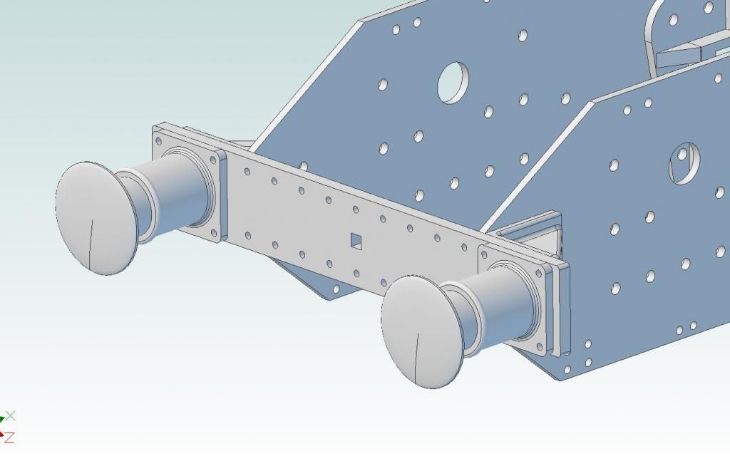 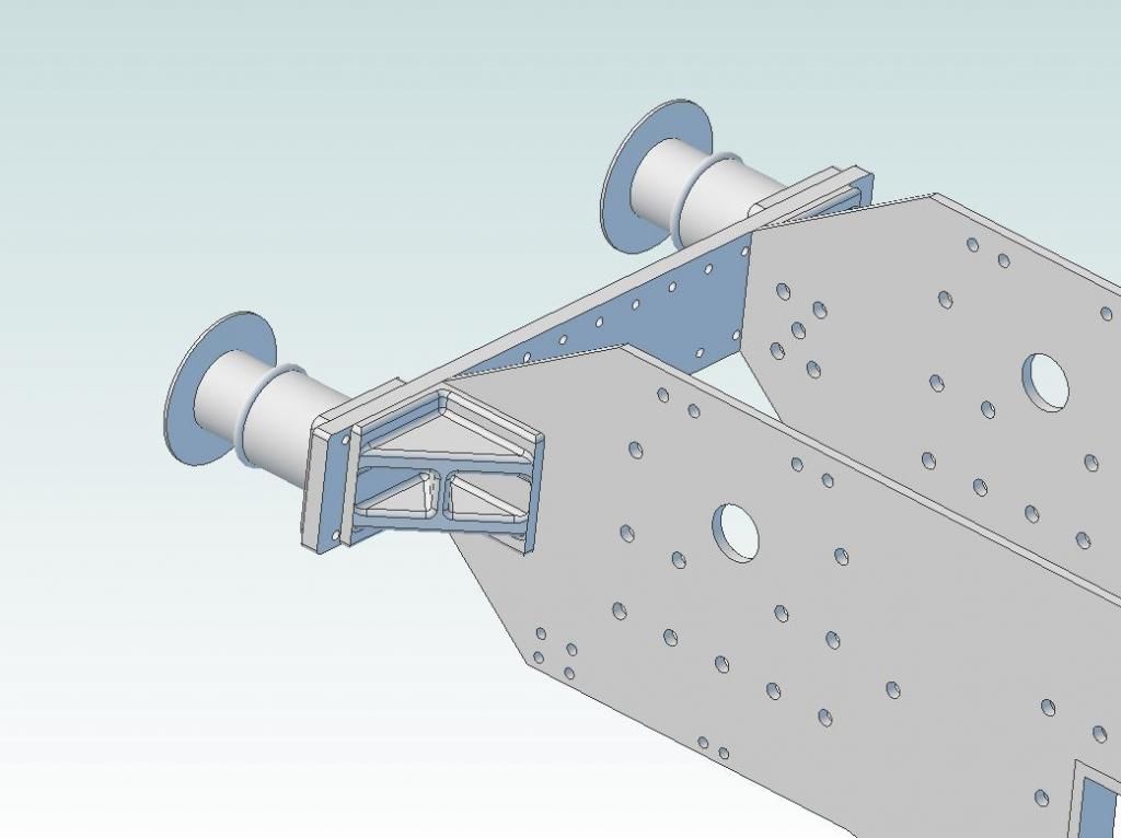 I'll remake the beam out of plate rather than angle. It needs a little tweaking as the mounting holes for the buffer stocks are showing as drawn, I'll measure the castings I have and revise the sizes. I've also left out the internal support brackets and the mounting holes in the buffer beam, I'll probably use countersunk rivets. Thinking of mounting the stocks with countersunk bolts through from the back, hidden by the gusset, Or with hex head through the edges of the gusset, depending on how much meat I've got available. |
|
jma1009
Elder Statesman

Posts: 5,900
|
Post by jma1009 on Nov 3, 2014 22:32:35 GMT
hi rob,
countersunk screws would never have been used in such an application (your buffer stocks) in fullsize. so tap the buffer beams! you will still have to lift the loco via the beams rather than the buffers whatever method you use with self contained buffer stocks, so doesnt matter a jot.
cheers,
julian
|
|
|
|
Post by Rob on Nov 3, 2014 22:51:24 GMT
Evening Julian, are you thinking bolt through from the front into tapped holes in the beam, or studs and nuts?
Looking at Roger's photos, I can see what appears to be a bolt through from the back of the gusset flange, through the beam and through the stock, with a nut and washer at the front, so was thinking of replicating that. Though, thinking about it, it may look neater with a nice hex headed bolt from the front!
|
|
jma1009
Elder Statesman
Posts: 5,900
|
Post by jma1009 on Nov 3, 2014 23:22:31 GMT
hi rob,
if you turn up your own bolts you can rebate the heads to simulate studding, though ive always fitted 8BA small hex head bolts to 5"g GWR loco buffer stocks tapped into the buffer beams.
cheers,
julian
|
|
|
|
Post by Deleted on Nov 4, 2014 9:09:18 GMT
Hi Rob As per Julian, Don's design also uses 8 BA bolts tapped into the beam...for the tender this is all there is, however the loco is far more involved with it's very substantial buffer housings that are secured to both the beam and the frames..iirc 6 x 8 BA to the frames and 3 7 BA to the beam, 4 gussets are fitted to the inside of the frames with 6 x 8 BA screws eachplus the brass right angle mounting frames using 14 x 8 BA screws plus 18 x 1/16 rivets....quite a lot of support but I still wouldn't attempt lifting under any circumstances though......  Pete |
|
|
|
Post by stuartk on Nov 4, 2014 18:47:09 GMT
Evening everyone,
I constructed my buffer beam from 32x32x5 angle - secured to the frames by countersunk screws into tapped brackets. I have fitted buffers (inc step plates) from Polly (Practical Scale - GWR parallel) these match the gussets from Blackgates. I have not secured the gussets to the frames - just fitted dummy rivets - the buffers are bolted on through the gussets as per full size - yes - I have to remember not to put full weight of loco on buffers when lifting. After trial assembly, the buffer beam was finished to length.
It may not be to scale .. but when fitted with steam heat and vacuum pipes etc - in my eyes it looks right, and that is all I aspire to!
For my loco toolbox, I have cut down a laser cut 'Pansy' box - again not sure if it is to scale - but it looks right.
Hope this has been of interest - loco operates at Reading SME
Stuart
|
|
|
|
Post by Rob on Nov 4, 2014 19:00:45 GMT
Evening Stuart,
It certainly has been of interest! That's another vote for the countersunk screws through the frames into angle brackets. I was going to check this evening if there was enough meat on the gussets to allow for bolts to pass through from the beam as I remembered them being very narrow. What size rivets did you go for? I've drawn 3/32, and have ordered some to gauge scale in person. Copper this time, as my iron riveting always seems to look shoddy!
Do you have any pictures you could share?
Cheers,
Rob
|
|
|
|
Post by stuartk on Nov 5, 2014 20:32:19 GMT
Rob,
I made a trip to the SVR and made my own album of photos of 1501, before I started. I then worked from the photos, choosing rivet sizes etc to best match the prototype - and did not consciously select any particular size of rivet - just chose what looked in my eyes the best match from my stock boxes !
There are some good photos of the front buffer beam etc on (Roger's ?) Wiki - 'The real thing Building LBSC's Speedy' Do look before finalising your design.
Do not worry about your riveting - after draw filing the buffer beam 'face' - there should be no marks of the 'bracket' rivets - all the 'rivets' on the face of the buffer beam and the gussets are cosmetic !
Will see if I can find any photos - I think my loco will be on our club stand at Sandown - and would be happy to have a natter.
Regards,
Stuart
|
|
|
|
Post by Deleted on Nov 5, 2014 23:16:52 GMT
Hello stuart-------"Beauty is is in the eye of the beholder"......and ...."If it LOOKS right, it usually is"........I think you have the correct approach to this because at the end of the day our models are "on show" 24/7...100% of the time, but might only visit a track half a dozen times in the running season so appearances are all important....That's not to say it must be absolutely technically "all present and correct, Sir !!" (life's too short for one thing )....but that which you do have on show needs to look proportional and balanced....................PS, How come you guys at Prospect Park make so much money from the tea room each Sunday ?? I was born in Liebenrood Road ( Delwood Hospital)... moved to Telford, now a "Country member" so get the Secretary's reports each time......PS}----Next time you fancy a look over 1501 why don't you and Roger get your heads together and I'll organise another guided visit for the pair of you ??
|
|
dscott
Elder Statesman
Posts: 2,437
|
Post by dscott on Nov 6, 2014 9:48:11 GMT
Beauty being in the eye of the beholder put an attractive (40 plus in our cases) lady doing the teas and the money comes rolling in. Now if they had had a Chinese lady in charge the takings would have been up last Sunday!!!!!
I am still getting to grips with the Paddington drawings and one thing that does stand out is that it is a simple matter of following what is drawn only on a smaller scale and it will look right first time. Plus once the pieces are in the computer they can be scaled to any size you wish, there being so many bits that can be so successfully built up from laser cut plates and made to look so realistic.
David.
|
|
|
|
Post by Rob on Nov 6, 2014 10:39:56 GMT
Hello stuart-------"Beauty is is in the eye of the beholder"......and ...."If it LOOKS right, it usually is"........I think you have the correct approach to this because at the end of the day our models are "on show" 24/7...100% of the time, but might only visit a track half a dozen times in the running season so appearances are all important....That's not to say it must be absolutely technically "all present and correct, Sir !!" (life's too short for one thing )....but that which you do have on show needs to look proportional and balanced....................PS, How come you guys at Prospect Park make so much money from the tea room each Sunday ?? I was born in Liebenrood Road ( Delwood Hospital)... moved to Telford, now a "Country member" so get the Secretary's reports each time......PS}----Next time you fancy a look over 1501 why don't you and Roger get your heads together and I'll organise another guided visit for the pair of you ?? Hi Alan, I've been fancying a look at 1501 for about 5 years now  . I'm always up for a visit, but I believe Roger has too much to do in the next few months and hasn't got too much spare time. Roger, forget everything else, this is clearly most important!  Beauty being in the eye of the beholder put an attractive (40 plus in our cases) lady doing the teas and the money comes rolling in. Now if they had had a Chinese lady in charge the takings would have been up last Sunday!!!!! I am still getting to grips with the Paddington drawings and one thing that does stand out is that it is a simple matter of following what is drawn only on a smaller scale and it will look right first time. Plus once the pieces are in the computer they can be scaled to any size you wish, there being so many bits that can be so successfully built up from laser cut plates and made to look so realistic. David. Hi David, Every time I think I don't need to spend the money on the Paddington drawings you say something else that makes me think I should Cheers, Rob |
|
dscott
Elder Statesman
Posts: 2,437
|
Post by dscott on Nov 6, 2014 20:19:05 GMT
The other way of looking at this is that the more drawings you have or have access to the more hints and tips you gain. Often the choice of material etc or the combination looked at differently. I am resting the quite large drawings on the floor tonight as my arms are aching from painting ceilings ( workshop of course ) and there are nice detailed bits covering clearances for silver solder and a hint about a 10 degree taper on the outside on stay holes instead of the usual countersink?
The tanks are a work of art and feature an as prototype joints in the middle of it and a curve round the boiler, great absence of rivets as the full size were welded.
David.
|
|
|
|
Post by Roger on Nov 6, 2014 20:52:18 GMT
With regard to the tanks and the curve, I'm inclined to shape them in such a way as to allow for a decent amount of insulation so the water might actually be of some use for injectors. I'm convinced that it ought to be possible to insulate them well enough so as to not get too hot.
|
|
|
|
Post by Rob on Nov 6, 2014 23:29:28 GMT
Here's one I'm finding hard to understand, perhaps you chaps can help me: 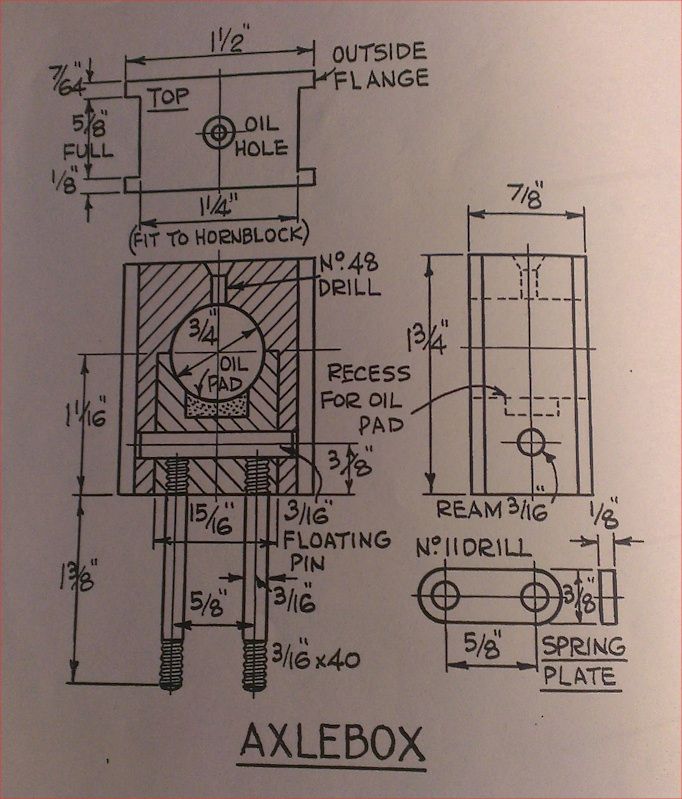 The drawing shows the axlebox as 7/8" deep in the side elevation, yet in the top elevation it's shown as 55/64" deep. What does LBSC mean by "5/8" Full"? One of these sizes is presumably wrong, unless I'm missing something! Cheers, Rob |
|
|
|
Post by Deleted on Nov 7, 2014 0:00:22 GMT
Hi rob----- no, you're not seeing things and YES, he has shown two different sizes for the same dimention...He used that term FULL ( or sometimes he'd say "The thickness of an HB pencil line" when viewing a port opening )...to mean approx 0.010" clearance.....If it helps any you can do away with the rear or inner flange and make that outer flange at 1/8".....Here's my Manor centre axle showing what I mean >>>>>>>>>>>>>  |
|
|
|
Post by Rob on Nov 7, 2014 0:03:55 GMT
That makes sense, thanks Alan |
|
|
|
Post by Deleted on Nov 7, 2014 0:30:33 GMT
Also, with that spring plate he shows (sort of) a No.11 hole as clearance for the 3/16" spring pin ..This gives you only 0.004" ...I would change that to 7/32"diam....This will allow the axlebox to tilt freely..If you're concerned that the coil spring might catch in this larger hole then fit a 3/16" thin washer between the spring and the spring plate...This will allow the spring to slide along the spring plate .......Finally, you don't need to have the "Inner" part of the axlebox as a sooper-dooper fit at it's top part....In fact you could make that 1" with all else the same sizes as shown.....It's not essential to have the bottom half of the axlebox touching the lower half of the axle..In fact full size only have the top half anyway...The lower half being a loose-fitting box containing the spring-loaded worsted trimmings and an oil sump...
|
|


 . I'm always up for a visit, but I believe Roger has too much to do in the next few months and hasn't got too much spare time. Roger, forget everything else, this is clearly most important!