|
|
Post by Roger on Nov 7, 2014 7:42:09 GMT
Yes, he's probably thought that the flanges where the same thickness. It's only the outside one that matters are Alan says you can make the axleboxes any thickness you like.
Take a look at my Wiki again and you'll see that the flange isn't flat either, you'll eventually need to taper it either side of the axle centre line or it will bind up.
I also followed Julian's good advice and added two of those floating pins to stop the bottom from rocking and it has the other advantage of missing the tapped holes for the spring hangers.
The top of the axlebox allows for a larger storage volume of oil if you want to do something about that.
|
|
|
|
Post by Rob on Nov 7, 2014 12:18:07 GMT
Hi Roger, Yeah, the tapering of the flanges is on the list, as is a plan for an oil reservoir in the top of the box, though I'm probably not going to go as far with my oil ways as you have  . Did you add 1/32" to the outside flange thickness of the boxes to accommodate the 4 11/16" GL5 standard, or relieve the back face of the tyre? I'm assuming that an additional 1/32" on either side isn't going to affect the rods/gear a great deal. I'm also assuming 1/16" end float is too much, so something needs to change. |
|
|
|
Post by Roger on Nov 7, 2014 16:16:14 GMT
You can open the drawings and models for those in my dropbox. I made them a little oversize and ground them down to give me exactly the end float I wanted on each axle. The Wiki gives the figures for the end floats. You don't want any significant float on the driving axle.
I used the dimension of the outside of the frames as my reference point because my frames are nominally 4mm but not actually close to that. I'd just check your actual distance over the frames, take that from the inside of the GL5 back to back measurement then divide it by 2 and add a bit for adjustment to get the flange thickness. It's easy to take a bit off, not so easy to go the other way. That's why the jig is designed to go on the grinder to trim the thickness of the axlebox when it's finished.
|
|
|
|
Post by Rob on Nov 7, 2014 16:56:31 GMT
As my frames are nominally 117 thou I adjusted the dimensions of the stretchers etc. to be 4.141 to give me 4.375 at the outside of the frames, I thought it was better doing it that way rather than the other way around.
Keep forgetting about that drop box! I did try downloading your LH frame assembly the other night, though whilst the individual parts appear to open no problem, there are file version problems with the assemblies themselves.
|
|
|
|
Post by Roger on Nov 7, 2014 18:06:47 GMT
I can't say I'm surprised that you can't open them all, I didn't expect you to be able to open any of them to be honest.
In that case you can copy the whole lot if you fancy it and see how you get on making the whole thing work!
|
|
|
|
Post by Rob on Nov 16, 2014 0:50:06 GMT
Not much of an update, but a question for Roger instead!
When you were modelling the pistons and crossheads, did you have any issues with the length of the piston rod as specified? LBSC seems to suggest that the piston rod can be moved back and forth in the crosshead boss to get the correct clearance for the piston at front dead centre, but I have my piston rod against the back face of my crosshead boss, and the piston protrudes out of the front of the cylinder, and doesn't travel all the way to the back.
I've double checked the sizes of my piston/piston rod, the crosshead, and the connecting rod, and all seem to be correct!
|
|
jma1009
Elder Statesman

Posts: 5,900
|
Post by jma1009 on Nov 16, 2014 1:01:54 GMT
hi rob,
dont expect much of any of the designers re piston rod length. roger has his cylinders further forward in any event on the frames. i make the rods overly long anyway due to the risk of score marks on the rod in the chuck if the damn thing slips, then cut to length and cut again and file to precise length to fit the crosshead as a press fit till end clearance for the piston is equal each end of the cylinder. i have a few worn secondhand reamers that provide the perfect press fit! i always drill then ream (with said worn reamers) the whole way through the crosshead for the piston rod. (i have a selection of 4 sets of various reamers, 1 for non ferrous stuff, 1 for steel, 1 for cast iron, and the above! and another 5th set of taper reamers from 1/64" going up to 1/2" dia).
cheers,
julian
|
|
|
|
Post by Rob on Nov 16, 2014 1:12:09 GMT
Thanks Julian, I had been worried that perhaps I'd drawn something fundamental incorrectly somewhere, which is a bit of a worry as I intend to use my drawings to drill the rest of the holes left off LBSCs frame drawings very shortly.
It may be that I've skipped over it but I could not find any reference to making the piston or the piston rod in LBSCs writeup, only the final assembly, so there were no clues about shortening there either.
|
|
|
|
Post by Roger on Nov 16, 2014 9:58:05 GMT
Hi Rob,
Actually, I haven't drawn those parts yet so I haven't checked. I'll be doing my own thing in that department anyway so it's not something I'll even bother checking. I'd model it and make the rod to suit the model then it can't be wrong.
|
|
|
|
Post by Rob on Nov 23, 2014 23:41:55 GMT
It's been a little while since the last update, and to be fair I've not done a great deal, but I am making some progress with the axleboxes. The cast iron, roaming free in its natural habitat: 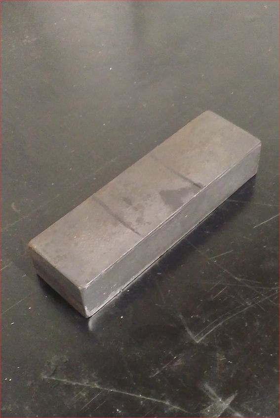 (I like how they felt the need to illustrate what to do with this with the marker lines... I don't think I could have worked it out myself!) Captured, skinned to near size, and cut using the very helpful instructions: 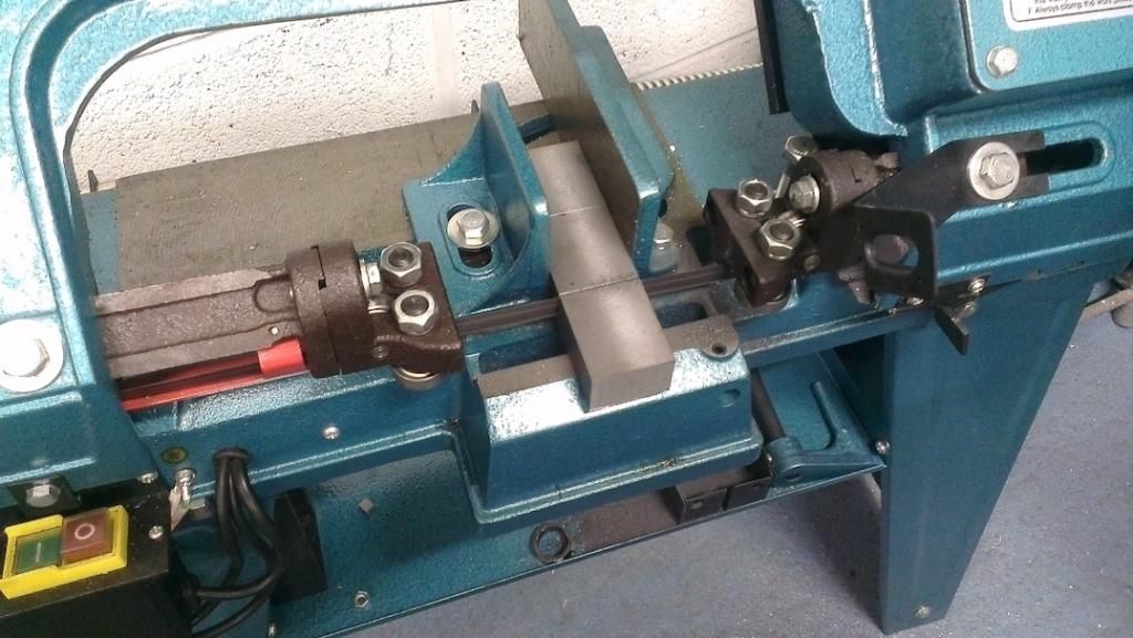 That saw is brilliant, I'd been meaning to get one for such a long time. In the end I got so sick of hacksawing through 2 inch steel bar, I went out and bought one the same day. The finished blanks: 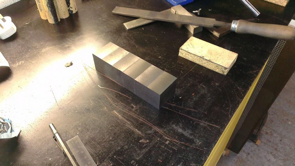 Next job is the slot for the keep, I did these two at a time as a matched pair in an attempt to keep the dimensions the same for each axle: 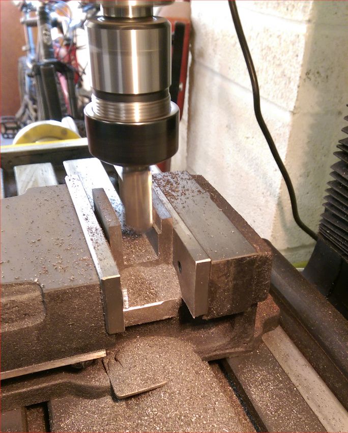 Getting there! : 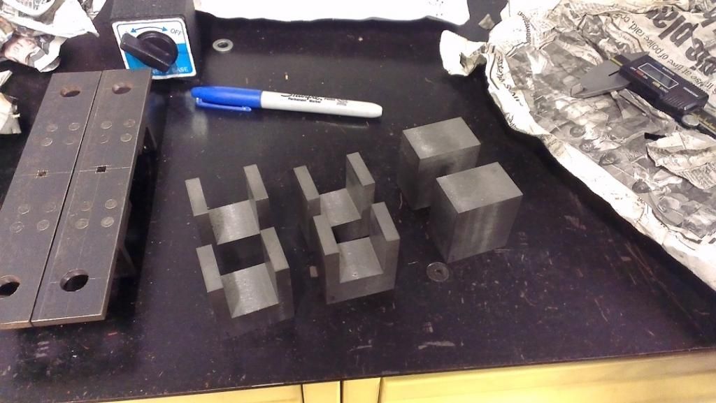 Note the old buffer beams in the photo above, I'll be replacing these with something more prototypical. Next job was to turn this: 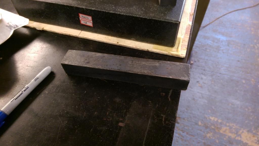 Into this : 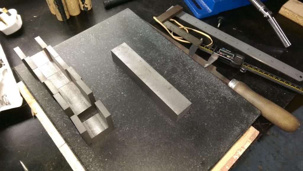 And finally, into these : 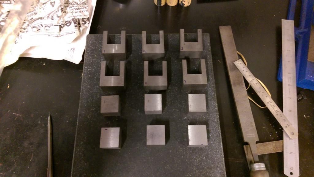 I have left both the boxes and the keeps oversize, I'll finish them to size together once they're pinned and I can work out exactly what size each one needs to be to take out the inevitable error in back spacing I'll encounter once they're in the frames. Who knows, could I have a rolling chassis by Christmas? I can only hope! Cheers, Rob |
|
dscott
Elder Statesman
Posts: 2,437
|
Post by dscott on Nov 24, 2014 16:56:57 GMT
I thought of a new competition this afternoon while insulating our new french doors outside in the sunshine.
We need a project to put all the bits we either make to original drawings and get fed up with or reject
from the now becoming perfect Speedy or Super 1500. I passed the bufferbeams again just now and they have to go!!!
We could all put them on e-bay and see how much we get for them allongside Winston catalogues!!!
Or does anyone have other sugestions?
|
|
|
|
Post by Rob on Nov 25, 2014 20:58:00 GMT
Alas, the buffer beams aren't the prettiest of items so I don't think we'd get much for them on Ebay, nor as a sort of sculpture! On a somewhat related topic, is there an issue with galvanic corrosion if you use copper rivets in steel? I had decided to use copper rivets in the buffer beams because I thought I'd have an easier time of getting a nice finish on such a highly visual part than if I use iron, but as usual, now I'm no longer sure. I also can't decide if paint may be an issue with the differenct metals. Opinions please chaps |
|
jma1009
Elder Statesman
Posts: 5,900
|
Post by jma1009 on Nov 25, 2014 21:53:05 GMT
hi rob,
copper rivets should not IMHO be used in such important structural locations as buffer beams. you need to use proper soft iron rivets.
ive plenty of 1/8" dia soft iron rivets if you want some.
cheers,
julian
|
|
|
|
Post by Rob on Nov 25, 2014 22:20:20 GMT
Hi Julian,
Appreciate the offer, but I think I was a little unclear with my post - the copper rivets would be decorative only. I have 1/8" iron rivets for the 'real' mounting.
Cheers,
Rob
|
|
jma1009
Elder Statesman
Posts: 5,900
|
Post by jma1009 on Nov 25, 2014 22:23:43 GMT
hi rob,
for 'fake' scale rivets no problem using copper at all, just dont use ali! ive always used 5/64" iron rivets for such things myself.
cheers,
julian
|
|
|
|
Post by Rob on Nov 25, 2014 22:34:02 GMT
Ah good, I'm glad you said that Julian as I've just ordered 5/64" in the last few days as my 3/32" just looked a little on the large scale. I'm thinking 1/16" for the platework, so have ordered some of those for size comparison.
|
|
|
|
Post by Roger on Nov 27, 2014 10:59:56 GMT
That's looking very nice Rob, they're coming out really well. You're right to leave a little extra on the outside to set the axle end float in my opinion. The most important part of this whole procedure is looming now... ie getting those axle holes the same distance from the chosen reference horn face. Don't assume that you can get them all spot on in the middle. Assume that the hole will be slightly out and make sure that you know which way round each axlebox is to the front of the locomotive. I'd mark them all up so you can match axlebox to horn in the same orientation.
|
|
|
|
Post by Rob on Nov 27, 2014 11:25:50 GMT
Morning Roger, Yeah, I'm not looking forward to that bit at all. I still haven't decided how best to proceed, whether to use your fixture or another method. I'd like to do them in pairs, but that has the potential to double any error. Can't decide whether it's better to bore them in the mill (with the benefit of the DRO), or attempt to do them in the lathe. I could spot the hole in the mill and clock this up in the lathe, but then each box would definitely be individual! Don't worry, I assume that all of my work is out so tend to work one piece at a time I'm tempted to bore the holes before cutting the slots for the hornblocks, that way I could adjust the slots to keep the axle in the right position with it in place between the two axle boxes. I realise this probably seems simple to you chaps with more experience, but for me it's a worry! |
|
|
|
Post by Roger on Nov 27, 2014 11:44:53 GMT
It's a worry for anyone because it's important and tricky to get very accurate. Personally, I don't think you'll get them more accurate than by using a fixture in the lathe that stays put for all the axleboxes and uses the same reference edges. You just have to remember that three go in one way and three the other. You can also clock the face of a fixture so you know it's running dead true.
Anyway, you know where it is if you want to use it.
|
|
|
|
Post by Rob on Nov 27, 2014 12:46:24 GMT
Cheers Roger, and I think you're right - but that relies on me cutting the slots in the axle boxes accurately too, as that's the face your fixture uses as the datum, unless I'm mistaken.
To a certain extent, provided the axle holes are in the right position and the right diameter, I can massage the slots to get them to line up across the frames. Though, I am talking in terms of thous here, not 16ths, I hope I can get them that close!
Ultimately, I don't know what to do for the best, as I can see merit in all of the different options.
|
|


 .
.
