|
|
Post by Roger on Jan 28, 2015 20:56:34 GMT
It's annoying that they're so mean with the machining allowance, it just makes life unnecessarily hard.
I hazard to suggest anything really, because there are as many ways to go about this as days in the month, but here's one way. To me, the challenge is to hold it firmly without it distorting. Some directions are going to be a lot more capable of taking clamping forces than others. The most obvious one I'd avoid is the tempting one across the two big flanges. I really wouldn't do that, but others are sure to disagree.
Before you decide to machine them together, I'd be inclined to double check that those outer faces that are standing upright are true to each other. You may find that in machining them as a pair, the flanges look wrong because they end up tapered. If that's the case, I'd separate them first.
If it all looks pretty true, I think I'd try to make that big flat surface (that's sitting downwards on the plan) sit down on a flat surface using a file. Then I'd clamp that down to the bed and take a flash off the tops of those flanges we can see.
Then I'd put it in the machine vice across the edges of the flanges that are currently standing up vertically, again filing the edges until I could feel that it was being held on many points while being tapped down to sit on those edges you machined earlier. You can get a reasonable grip across in that direction, more so than if you try to hold it across the big flat flanges. Do check that the big flanges with a square to make sure they are at 90 degrees to the fixed jaw.
I'd set one of those big flat faces just clear of the jaws so that can be cleaned up after you've machined the back.
Now you have two reference faces and the rest of the operations can be done keeping those clamped to the fixed jaw or against the base of the vice. These are your key reference points.
Do tram the head on the mill if you intend to use the geometry of the machine to create any of the right angles.
|
|
|
|
Post by Deleted on Jan 28, 2015 22:20:08 GMT
Hi Tom
I'm assuming you have similar machine tools to myself...ie a basic lathe and mill..if so I would machine these as a pair. Looking at the dimensions they look like they will fit into a standard 4" machine vice which is probably what most of us have in the workshop. Like most things there would be a number of orders in which to tackle this which only you can really decide on as you have the casting to hand and thus can see what looks best to start with. However I will say in which order I would tackle this with what i have here....
I'd take a look at the largest flat surface to see how flat it actually is, if ok I'd use a file just to get any lumps and bumps out of the way. Check with a vernier to see that the flanges are the same thickness, I wouldn't worry if it's a few thou out as this would be invisible to the human eye, the important thing is to get the thing flat and corresponding surfaces square to it. Next check the heights of the two ends, these need to be the same. Put a suitable piece of steel flat bar in the machine vice to support the casting keeping it level while held upside down in the vice. If required use packing to support the casting in the middle, the two outside legs should be held in the vice if i've read the size right on the plan. Don't worry about the casting being square along the longitudinal axis, it's not critical at this point, machine the flat surface taking light cuts until you are at the correct flange thickness shown on the plans. Next I would turn the casting over still using the flat steel bar as support and machine the two ends to their correct height. Before machining the end faces square I would stand the casting on it's edge ( you may need to file one edge flat/square first) and machine to size, turn over again and machine the other side. Next job will be to machine the two ends, you will need to do these one at a time in regards to holding the casting, having each end in turn just sticking out of the ends of the vice jaws to machine, you may need a long series cutter here and a sharp one at that. Finally you can cut the casting along the centre line with a hacksaw and place the two castings in the machine vice with the hacksawed edge upwards using packing to keep upright for final machining, lastly do the various holes...
Of course there will be other ways of doing this, I'm just saying how I would tackle it with what I have here having no DRO and dodgy digital scales I would avoid machining these separately...
good luck
Pete
|
|
|
|
Post by Deleted on Jan 28, 2015 22:56:14 GMT
Thank You Pete and Roger.
Pete, yes, I have fully manual machines of dubious parenthood. No dro ... blind in one eye and can't see out of the other. I do, however, have soothing ale ... lots of soothing ale!
There are two surfaces that are almost flat, and a quick rub on 250grit paper on a glass surface got rid of the bumps. A quick check with the machinists square shows it to be not bad at all ... just a tad short on material.
Roger, because of the need for both of these to be identical, especially the angled part, I will do them together. Your way and Pete's way are similar so I will do bits of both and see what happens. If all else fails, Blackgates have more.
Cheers
Tom
|
|
|
|
Post by Jim on Jan 29, 2015 0:08:06 GMT
Hi Tom, To add to Roger and Pete's input I'd just add that for me the key issue was to ensure the the face that mated with the frames was square to the face that mated with the top slide bar. If they are square and from what you say they are then a very light cut to give flat surfaces would do as it is odds on as you start to assemble the brackets and their slide bars you'll discover you need shim packing to get everything true and lined up with the cylinder bore. I probably spent 2 days shimming and adjusting those brackets to ensure they lined up properly and that the cross heads on both sides moved freely through the full cycle. I took this photo when I'd got everything working freely. You can just make out a gap between the slide bar bracket and the frame because allowance had not been made in the drawings for the cylinder block mounting plate. I also had to cut away the leading web on both sides to accommodate the slide bars for the valve rods seen beside the bogie. I think this is the 'fitting' part of 'fitting and turning'. 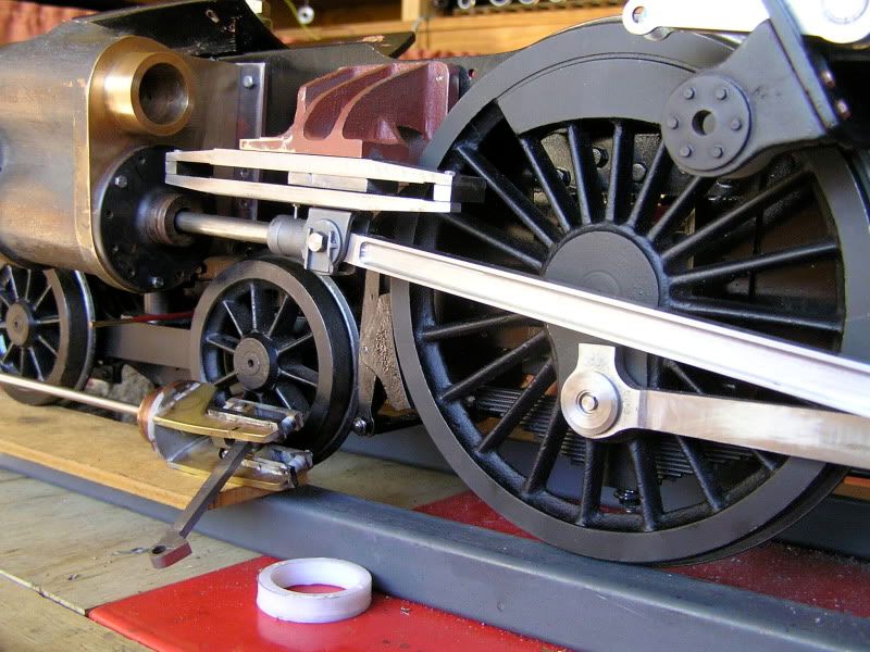 You'll get it all sorted with the help of a soothing ale or two.  Jim |
|
|
|
Post by Deleted on Jan 29, 2015 11:14:08 GMT
Thanks Jim. Is your engine a 3 1/2" or 5" gauge?
I am going to have a go later today when I get back from a short road trip for some supplies.
Cheers
Tom
|
|
|
|
Post by Jim on Jan 29, 2015 19:25:56 GMT
Tom Boadicea is a 5" gauge Britannia based on the John Perrier drawings and Wilwau castings. While there have been more recent and updated drawings done my impression from talking to other Britannia builders is that Perrier - Wilwau is still the basis for a lot of the work.
Jim
|
|
|
|
Post by Deleted on Jan 31, 2015 11:32:23 GMT
Thanks Jim. Well, a start was made at machining the guide brackets. My first effort had a very poor set up and only lasted a few seconds before there was a nasty noise, and the part was no longer in the vice. Annoyed at myself, I could see visions of having to ring Blackgates for another casting, but once I had looked everything over, remounted the casting and took a skim to see what I was left with. I have quite a bit of Corian cutoffs and you can see that is what I used to mount the casting. This way, I could hold everything very solid, and not have to worry about hitting the vise jaws with the cutter.  In the bottom left hand corner you can see the ding that the cutter put in. If machining to dimension doesn't get rid, then I can fill this with JB Weld. At this point I had to go and shovel 8 or 10 inches of wet snow, which hurt my hands, so there will be a day or so delay before I finish this part. Cheers Tom |
|
|
|
Post by Deleted on Jan 31, 2015 14:08:46 GMT
I got the end flanges finished and surprised myself with everything being square at this point. I started on the clearance channels and the first thing I did was get a bit of a flat bottom to use as a datum point.  Once that was done, I took the right side flange to thickness, and then took the bottom down to where it was supposed to be. Then, I worked my way to the left until the channel was the size it should be.  One side done except for some clean up. I will tackle the other one when I get back from chauffeuring duty. Cheers Tom |
|
|
|
Post by Roger on Jan 31, 2015 14:11:51 GMT
Annoying though it is, that's how we all learn. And let's not pretend that we don't all end up doing things like that once in a while! The main thing is that you've not damaged anything of significance and you have a better understanding of the cutting forces. So far, so good.
|
|
|
|
Post by Deleted on Jan 31, 2015 15:50:50 GMT
Roger, I wasn't aware how "sticky" this stuff was to machine. I had to be very careful with my "economy" cutters. That operation is done ... both channels to spec and some larger unwanted chunks removed.  Now I need to study the plan and figure out how to get the required angle on the bottom bit that the guide bar is attached to. Then, some cleanup with the Foredom and cut the two apart, and then ... a soothing ale. Cheers Tom |
|
|
|
Post by Deleted on Jan 31, 2015 15:57:26 GMT
Great work Tom.....I have to admit to not being aware of the channels hence why I made no reference to them before.....I think I should try some of this 'soothing ale'...seems to do wonders for you and Jim....  Pete |
|
|
|
Post by Roger on Jan 31, 2015 16:15:26 GMT
This looks very promising Tom. I'm not quite sure I would use the term 'sticky', it chips nicely with a razor sharp carbide cutter. Maybe I'm just spoiled! If you're using a cutter that isn't that sharp and you're cutting the whole edge with the side of an cutter then it could grab. I would only take the finishing cut at the full depth in that situation, the rest being removed in several cuts getting deeper with each cut.
Isn't it great when you see something like that with those lovely fine machining marks, I never get tired of seeing nicely machined parts.
|
|
|
|
Post by Jim on Jan 31, 2015 16:45:08 GMT
Well done Tom, you are making great progress there.
Jim
|
|
|
|
Post by Deleted on Jan 31, 2015 17:02:31 GMT
Thanks Everyone. The encouragement is working wonders.
Roger, I got a much better finish than I thought I would. I don't have any carbide cutters and I don't think my mill or lathe are rigid enough to use them.
I have a plan for the angled bit I need to do.
I am going to set up the angle vise to what I think is the proper angle. Then I am going to scribe a reference line in a piece of corian. If I mill to the line at one end, there needs to be 3/32" difference at the other end. I can adjust until it is correct. Then I just swap out the test piece with the real thing and away I go.
Cheers
Tom
|
|
|
|
Post by Roger on Jan 31, 2015 18:26:50 GMT
I think the finish looks really good, I'd be very pleased with that. I think it's a common misconception that carbide tools require significantly more rigid machines. In most cases I bet you wouldn't notice the difference. When it comes to milling cutters, I'd wager that they take less force because they maintain their sharpness long after HSS tools have given up. Why not try some cheap ones from eBay and see how you get on with them? I never use HSS these days for milling, there's no saving since they go blunt so quickly.
That sounds like a good plan for getting the angle, that's certainly going to work.
|
|
|
|
Post by vulcanbomber on Jan 31, 2015 20:09:36 GMT
I generally find people run HHS way to fast... think of a speed for a cutter, quarter it, then you'll be about right. It will then last all day.
|
|
|
|
Post by Deleted on Jan 31, 2015 20:30:44 GMT
Roger, I will check out some carbide mills. Our dollar has just done a huge nosedive against most other currencies, so it will be awhile before I order much. Vulcanbomber, I don't have the speed problem ... if my friends see me milling something, they usually tell me I am going too slow. My machine tells me when I am at the right speed by the noises it makes. You are correct though .. one of my friends goes through a set of mills every couple of months and he says that is normal. I am still working on the original set that are nearly two years old. For this last operation, I chose my small flycutter as I wanted a nice flat surface. My original plan worked fine ... once I adjusted the math. For the proper angle I needed to take 1/32 away from 3/32 which leaves 2/32. My first idea had a 3/32 difference which was going to give the wrong angle. I adjusted things and got it done ...  Now I just need to cut it apart and get out the Foredom, but I will do that tomorrow. Note ... no Soothing Ales were consumed during any of these operations. They will be now though. Cheers Tom ![]() |
|
|
|
Post by Roger on Jan 31, 2015 21:15:35 GMT
That's a job really well done, you must be really pleased with what you've achieved.
|
|
|
|
Post by Deleted on Feb 1, 2015 12:05:03 GMT
Roger, I am quite chuffed really, and mad at myself at the same time. I have had this casting for over two months and have put off machining them 'cause I didn't think I could do it.
In the end I just decided that the worst that could happen is I would have to get a new one. So, old dogs can learn new tricks.
Cheers
Tom
|
|
|
|
Post by Roger on Feb 1, 2015 13:13:33 GMT
Well, you've got no excuses now, you've proved you can do it and that's such a confidence booster. The great thing about Engineering is that you can cash in on this success and re-use what you've learned. There's no magic to any of it, you just have to get a feel for it and you're obviously getting the hang of it. Your previous comment about hearing what the machine is telling you is the key to it. I never use feeds and speeds from tables, I always use intuition and my ears. I think you're making a fine job of that casting.
|
|


