|
|
Post by builder01 on Jul 8, 2017 13:00:54 GMT
Need photos! Yes, it is a slight pain to do so. There are more detailed instructions on how to post photos on the first page of "General Chat". Flickr is a pretty good site to host your photos.
David
|
|
|
|
Post by builder01 on Jul 5, 2017 15:01:47 GMT
Hi Andyhigham,
Yes, I feel your frustration! What I have discovered with these old drawings, is that they are a suggested guide. You have to look at the parts that go together, and then decide for yourself what sort of a fit these parts need. This was a bit tough for a beginning locomotive builder like me, but, I figured everything out eventually.
A good example is the crank pins on a Super Simplex. The end of the crank pins that fit into the wheels is drawn as .3135" and the hole in the wheel they fit into is drawn as 5/16". Decimals and fractions are obviously mixed here. The pin will be turned to .3135" and the hole in the wheel is supposed to be reamed. Looking at these two dimensions, you can see that there is supposed to be .001" press fit of the pin into the hole.
One thing to consider here is that imperial sized reamers are usually described in terms of fractions of an inch, thus the mixture of fractions and decimals.
Rarely does a reamer make an exact diameter hole. The important part to take away from the drawing is that the pin is a press fit with an interference of .001". So, ream the hole, measure it, and then turn the pin so it is a press fit into the hole no matter what size the reamer decided to make the hole. At this point, because the reamed hole is probably a bit over size and the pin will be made accordingly, both parts are not made to the drawings, but the point of the interference fit is maintained.
If for some chance your 5/16" (fractional) reamer makes and exact hole diameter of .3125" (decimal), then the pin can be turned to .3135".
I can absolutely see how jumping between decimals and fractions can be frustrating not to mention throwing in a metric dimension now and then plus no tolerance given on the drawing. This is all part of the territory of using old drawings. I instantly saw this when I got my first drawings, but, decided it was not really a problem. I have been a machinist for about 30 years and I jump between the different measurement systems pretty quickly at this point.
I have nice big wall charts that help when I can't remember what the decimal equivalent of some fraction is. These charts should not be in some book, make them large and hang them on the wall!
David
|
|
|
|
Post by builder01 on Jun 17, 2017 22:54:15 GMT
I don't know what the new valve will have. Typically, the blower valve screws into the backhead with the same number of threads per inch as the blower tube, just a different diameter. The blower valve has both internal and external threads. The external threads screw into the backhead and the internal threads are for the blower tube to screw into. The fitting at the smoke box is probably made in a similar manner. For instance, my blower valve has an external thread of 3/8"-40 that screws into the backhead. The internal thread on the valve that the blower tube screws into is 1/4"-40. Your blower tube may be broken at this thread. If you can unscrew the blower valve, you may find the broken end of the blower tube in the valve. By the way, this assembly is a little tricky to get all threaded together. I used model pipe threads for the 1/4"-40 threads as they are tapered and tend to seal better as they screw together tight. A bit of trial and error is required to get the blower tube exactly the right length so it tightens up properly. David  21-778 Blower Valve 21-778 Blower Valve by Builder16, on Flickr |
|
|
|
Post by builder01 on Jun 15, 2017 20:38:25 GMT
Hi James,
Probably both the blower valve and the fitting at the smoke box end may have to be removed for inspection. The copper tube may be threaded on each end. One end threads into the fitting at the smoke box and the other screws into the valve on the back head. But, you say tube was soldered? Hmm.. it certainly is possible.
David
|
|
|
|
Post by builder01 on Jun 15, 2017 10:02:32 GMT
The full size ones only have 4 holes for rivets each side I tried both just one is quicker!! Then I got married again?  It is a Hobby! David. Geting married again? That is a hobby? |
|
|
|
Post by builder01 on Jun 7, 2017 20:04:26 GMT
Hi James,
What you have done so far sounds good. I must admit that I do not have first hand experience with a Stroudley type regulator. But, I do understand how they work in general. The main operating rod, probably is removed by coming out through the back head along with the handle and whatever sort of packing gland assembly there is. How the operating rod is attached to the part at the steam dome, I could not say. It may be something as simple as a square on the end of the operating rod that fits into a square hole in the bottom part of the assembly. It may just slip out.
Yes, there are connecting rods on the right and left of the valve. These go down to the operating rod. These need to be able to move up and down to rotate the steam valve, which is probably the part you can see when the dome is removed.
Hopefully others will chime in here.
David
|
|
|
|
Post by builder01 on Jun 7, 2017 16:21:00 GMT
Is this an older boiler that has not been steamed in a long while? If so, yes, regulator parts can certainly become stuck through lack of use and the passage of time. Probably the entire regulator assembly should be removed so it can be inspected, cleaned up, and to make sure all of the moving parts are working.
As for a hydro test, blocking off things is the best. In fact, blanking plates should be made for things that fit into or over large holes like some types of regulators and steam manifolds. Other things should be removed and threaded plugs made to fill other smaller holes. If you have too many things on the boiler, it may be difficult to tell where problems are, as you are in effect, testing everything at the same time. Isolate the boiler first, and prove it's integrity. Then you can start adding things on to it and prove each added component is working and is able to function properly at least to the working pressure.
David
|
|
|
|
Post by builder01 on Jun 7, 2017 1:17:27 GMT
Be careful about "several more re-heats to get it completely right". You may cause more trouble than you have right now.
David
|
|
|
|
Post by builder01 on Jun 6, 2017 18:02:36 GMT
Sometimes, it is possible to peen the stay and stop the leak. I don't mean beat on it. Annealed copper is very soft, you must be gentle. A few light bumps, even with a small piece of steel will cause the stay to spread and stop the leak. Do not strike the boiler, only the stay. I would try this before comsol.
David
|
|
|
|
Post by builder01 on Jun 2, 2017 13:46:58 GMT
Do not attempt a live steam test until it has successfully passed a hydro. Steam testing is potentially dangerous without a good hydro test first. Also, the hydro test will probably reveal the leaking areas.
David
|
|
|
|
Post by builder01 on May 31, 2017 0:13:46 GMT
Yes! That is the one! What a beautiful piece of locomotive jewelry!
David
|
|
|
|
Post by builder01 on May 30, 2017 20:13:39 GMT
If you decide on a screw type reverser, instead of a lever and quadrant, it works well. But, a double lead thread is the way to go. If you want the nut to travel forward for the forward direction of the gear, it needs to be a left hand thread. I used a double lead 1-1/4" 20 thread, which is actually two 1/4"-10 threads. One centered between the threads of the other. The thread dial on the lead screw can show you where to place the two starts on the shaft. Since the thread form is the same a a single lead 1/4" - 20 thread, the pitch diameter is also the same for a double lead. You can use thread measuring wires to know when the male thread is exactly to size without using a nut. The nut can then be cut to fit the shaft. I did not cut the nut with a tap, it was single point cut with a miniature boring bar ground off hand from a square piece of HSS.  DSCN0914 DSCN0914 by Builder16, on Flickr  DSCN0911 DSCN0911 by Builder16, on Flickr I think someone on this forum has actually done a screw type reverser with a miniature Acme thread! This would be more to scale, but, the 60 degree form works just fine. David |
|
|
|
Post by builder01 on May 25, 2017 23:18:23 GMT
Thanks so much Julian!
Yes, there are very few UK style locos built in the USA and even fewer locos with copper boilers. I had long list of requirements for a first time loco and this one seemed to be what I needed. There was not anyone at my club that had any experience making a copper boiler. Most of the locos on the 1"scale track are diesel/electric. I really had to teach myself and used your boiler thread as a guide.
As you say, I did make a few adjustments including squeezing the gauge to 4-3/4" and reducing the cylinder bore to 1-3/8". It seems to have plenty of power and can easily spin the wheels. Hopefully this has reduced the steam needed for these hungry cylinders.
I actually finished the boiler and hydro tested it at the end of December last year. I did not want to announce anything until I actually had a certificate. I did not know if I had a boiler, or, a boiler shaped object until just a few days ago! The last 5 months has been out-fitting the boiler getting it ready for steam.
23 months from laying out the frames to going for a ride behind the locomotive! It's far from finished, but, in the meanwhile I will have a lot of fun with it!
David
|
|
|
|
Post by builder01 on May 25, 2017 22:59:01 GMT
Brilliant work! You will have to talk to Gromit about not catching the spelling error in the first photo. "Driving wheel 32mm Coat fired loco"?
David
|
|
|
|
Post by builder01 on May 25, 2017 16:26:05 GMT
James,
Your "restoration thread" should probably be a new thread started on the "general chat" page. Perhaps the moderator can move it for you.
At any rate, you say the boiler does not leak. Is this after a hydro test? Or, just filling it with water and looking for leaks? I would never start a fire in a boiler that had not been hydro tested, this is very dangerous even at a low pressure. If it hydro tests successfully, then you can start to test with compressed air rather than starting a fire.
David
|
|
|
|
Post by builder01 on May 25, 2017 16:13:42 GMT
Hi Pete,
Actually, I was asking the original poster. I did not realize your name is Peter also! Sorry about that! Now it is me that has not read carefully! In any case, the question for the original poster still remains, smoke box, or, fire box?
David
|
|
|
|
Post by builder01 on May 25, 2017 13:34:21 GMT
Hi Peter,
You have labeled your thread "heat shield on smoke box door", but, your text says "fire box door". Both are good questions, but which one are you meaning?
David
|
|
|
|
Post by builder01 on May 23, 2017 0:51:06 GMT
Finally was able to get to my club track to get my boiler inspected, tested and certified this past weekend. Everything went quite well. No name plates or hand rails, (yet), just pure miniature steam locomotive! Plate work will no doubt be next. By the end of the day I was able to take my locomotive all the way around the track, without stopping!! Not bad for 23 months of work. A special thanks goes to the guys that help me at the Finger Lakes Live Steamers club in Clyde, New York. Also, thanks goes to folks on this forum and especially to Julian Atkins for his boiler build thread and other words of wisdom. Thank you for taking the time Julian! With his explanation of the use of propane and simple techniques, I was able to build this boiler completely by myself. Keeping a good fire going in a small locomotive is a real art!! I can't wait to get some more practice!! 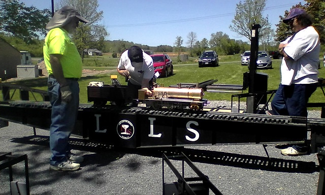 IMG_20170520_135701 IMG_20170520_135701 by Builder16, on Flickr 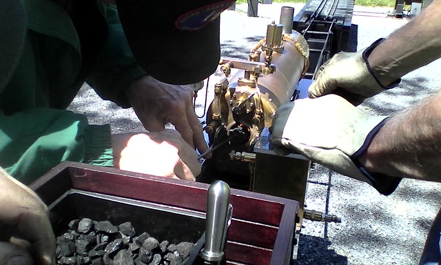 IMG_20170520_134300 IMG_20170520_134300 by Builder16, on Flickr |
|
|
|
Post by builder01 on Apr 15, 2017 3:51:51 GMT
Instead of the seat, why not the ball? PTFE ball are available from McMaster-Carr in all the right sizes. Not too expensive either. David Hi David, I'd be interested to hear the results of any tests with PTFE balls. My gut feeling is that they're too malleable and would take up a permanent set in one position which might prevent them from seating in another. I'm not sure how round they are to begin with, but that might not be important. Yes, it is quite possible that PTFE might be too soft, although, it is mentioned in the catalog description that they are used in ball valves. I'm not sure if this is the same purpose as a check, or, clack valve like we need. Viton is another possible of a "drop in" solution. Currently all my clacks have stainless steel balls. So far, so good! Time will tell if this is the way to go or not. When the time comes, a ball of different material will be easy enough to try. I have noticed that it is much easier to get a ball to seal well on brass rather than any type of bronze. This may be because the brass is softer and can conform more easily than bronze to a ball being "tapped" to form a seat. Just a guess. David |
|
|
|
Post by builder01 on Apr 14, 2017 12:41:27 GMT
O rings and the check valves as shown from Baggo are probably fine solutions. But, will probably require a slight modification of the clack body. Changing the material of the ball offers a "drop in" solution with no modification of the clack body that has already been machined for a ball.
David
|
|


