Lisa
Statesman

Posts: 806 
|
Post by Lisa on Jan 23, 2019 16:17:04 GMT
An alternative option could be to make a set of patterns, then see if you can broker a deal with EJ Winter to sell them your patterns in return for cheaper castings.
|
|
Lisa
Statesman
Posts: 806
|
Post by Lisa on Jan 20, 2019 19:18:55 GMT
Other than tapping the pump hole (which I don't have the M12F tap for yet), the pump stretcher is now done. It could still do with a bit more cleaning up though; I might leave it in vinegar overnight or something.  This then meant I could bolt bits together for a look for the first time.  Yes, the back of my bench is a mess. |
|
Lisa
Statesman
Posts: 806
|
Post by Lisa on Jan 20, 2019 12:44:45 GMT
Well done Tim! That's got to be about the most complex slip eccentric arrangement I've seen, interesting to watch though; didn't even notice the wobbly rim till I read the rest of your post.
|
|
Lisa
Statesman
Posts: 806
|
Post by Lisa on Jan 20, 2019 8:31:42 GMT
This page would be more impressive, really, if only the methods of LBSC or Martin Evans were used. Roger should prove for once, that he can make such part purely using traditional, manual methods. Johannes We'll all just read your loco building thread for that Johannes... uh, where is it? Roger certainly has nothing to prove, he does things his way, as do we all. |
|
Lisa
Statesman
Posts: 806
|
Post by Lisa on Jan 19, 2019 21:23:45 GMT
I like the way you have used the nails to keep everything in place for soldering, I'll remember that for the future. Paul Thanks, the fire bricks I have are quite soft, it makes poking nails and screws in to keep everything aligned nice and easy. |
|
Lisa
Statesman
Posts: 806
|
Post by Lisa on Jan 19, 2019 21:21:25 GMT
Hi Lisa, The black was possibly worse at the edge because you had to concentrate the heat at the joint so it was hotter there for longer. Getting cracking with the job helps so that the flux doesn't get used up before the job is done. Another thing that helps is to form the Silver Solder into a shape that fits the joint. If you put lots of flux over it, the flux melts and thermally connects the Silver Solder wire with the metal so it doesn't melt into little balls, it's sitting in a pool of clear flux. This means you don't have to get the parent metal anywhere near as hot before the Silver Solder melts. You can join something like this with the metal barely glowing noticeably red hot. If you're adding the wire to the pre-heated joint, the joint needs to be significantly above the melting point of the Silver Solder before it conducts enough heat to melt it. You also have to keep the joint hot for longer while you mess about adding more Silver Solder and it's easy to end up with more than you need and it not being evenly applied. The result is likely to have much more black oxide because of this. That's pretty much how I did it; cut some straight lengths of solder, placed them tight into the corner of the joint with plenty of flux, then heated the lot in one go with a fairly large flame, rather than adding solder to a hot job. The steel was barely red, if at all, as you mention. I think, if anything the issue was that the flux was a bit too watery, as it dried out long before the job was up to heat. I do find it much easier with the solder already on the joint, once it's all hot it essentially just flashes in and it's done; rather than poking about trying to get it all even. |
|
Lisa
Statesman
Posts: 806
|
Post by Lisa on Jan 19, 2019 20:21:43 GMT
Nice and solid, a very good joint by the look of it. You can save a lot of time cleaning up that dreaded Black oxide if you paint everything with flux, not just the joint. I cover absolutely everything (both sides too) with it when joining Steel, it doesn't have to be a thick mix, it still works. There are usually a few spots that go black, but most of it needs no cleaning other than warm water and a brush. Thanks Roger, I'll give that a go next time. I noticed that the worst of the black was right on the edge of where the flux was, so not having an edge would help! |
|
Lisa
Statesman
Posts: 806
|
Post by Lisa on Jan 19, 2019 19:06:37 GMT
|
|
Lisa
Statesman
Posts: 806
|
Post by Lisa on Jan 19, 2019 10:42:36 GMT
The first workshop of dad's that I used had a floor of compacted ant hills; everything since then's been an improvement.
My current workshop is just a 1½ car garage with unpainted concrete floor, and rubber mats in front of tools and benches, which has so far worked well. The biggest issue is the front door that doesn't quite seal, resulting in leaves blowing in from outside.
|
|
Lisa
Statesman
Posts: 806
|
Post by Lisa on Jan 18, 2019 22:32:40 GMT
Speaking of changes to the pump stretcher, I was reminded of the setup of Oily Rag 's 'axle bush holders' on his 32mm gauge loco, and it occurred to me that something similar could work for dropping the pump in/out and would also alleviate my concerns about weakening the stretcher. 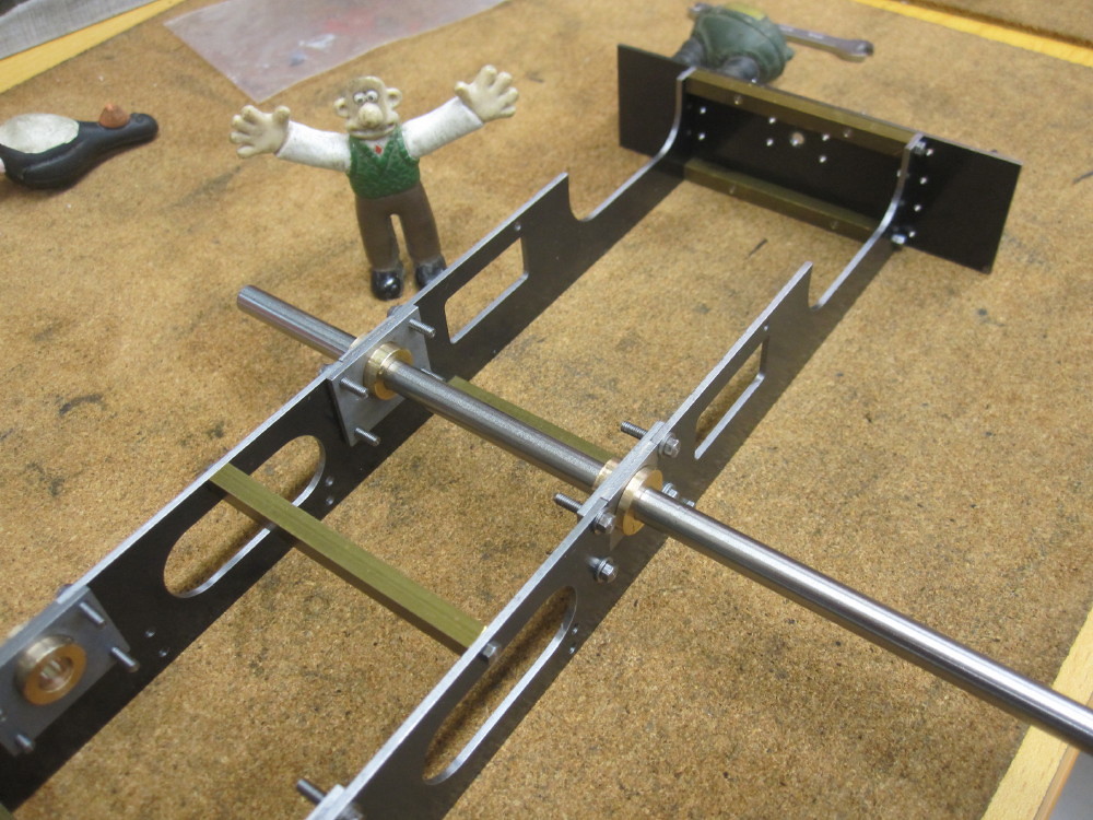 Image pinched from Daz's thread. Ultimately though, I'll probably just stick with 'as designed' and go with a tapped hole for the pump; as I could always just unscrew the whole stretcher and drop it out if needed. |
|
|
|
Lisa
Statesman
Posts: 806
|
Post by Lisa on Jan 17, 2019 19:06:45 GMT
Looks like all the clips are sped up; I've seen the originals for several of those. In reality they're going dead slow, less than walking pace in some cases.
|
|
Lisa
Statesman
Posts: 806
|
Post by Lisa on Jan 17, 2019 19:02:18 GMT
Milling the tabs on the pump stretcher is taking a while, but I think (hope!) it will be worth it when it comes to assembly.  I'm making them all from one strip that's been milled to the right height, then cutting in each piece and the tabs, leaving about 0.2mm to hold it all solid while machining. I'm aiming to make it about 1mm over length, so I can then mill it square and to length, then hole drilling will come last. |
|
Lisa
Statesman
Posts: 806
|
Post by Lisa on Jan 16, 2019 16:08:40 GMT
The hole that you have shown for the lubricator drive is an elegant solution to the 'as designed' bent drive-shaft passing below the pump-stay and leading axle. However, the hole that you have designed in looks to be on the same line as ("level with") the axle; if you follow LBSCs oil-pump location then you will have to joggle the drive anyway (slightly?) upwards to avoid (and to go over rather than under?) the axle. There is about 20mm between the pump stay and the axle(?). Of course you may have this covered and/or I may have misunderstood your excellent rendition of the plans. Depending on your exact layout and location of the oil-pump the drive-shaft hole may need moving up slightly or, if a significant joggle is still required consideration given to whether it is a worthwhile modification given your concerns about stay strength. Yeah, this occurred to me when I assembled it all in CAD, I've since moved the hole up a few millimetres so that the drive shaft clears the front axle. As regards the water pump itself maybe worth considering using a 1/4" or 6mm diameter pump piston which would be more than adequate for the job rather than the as designed 5/16" 8mm item. This would potentially allow you to thread the fixing hole in the pump stay M10 rather than M12 (1/2") as designed. I vaguely recall that LBSC's own Tich had a 3/16" (5mm) pump piston. Of course the size of the pump depends on where and how you drive, how you prefer matters to proceed (quick fill vs slow fill)..... and your attitude toward 'cruelty to small locos' regarding loads to be hauled! LBSCs own personal track was a level oval, so the demands on his locos may have been relatively reduced and he always applied "monkey gland treatment" to enhance the efficiency of his own locos, though I believe that he enjoyed a bit of speeding around! There is a thread on here somewhere about calculating pump requirements I think. If you later decide that you prefer a larger pump then opening out the M10 hole to M12 and making a new pump would be relatively easy, and given the topic heading......cheap! LBSC's pump ram/piston is an odd shape with multiple sizes, I think a plain ram of 6.5-7mm would probably be equivalent to his design, in terms of volume pumped. So 6mm would work nicely... on the other hand, I have some leftover 8mm stainless steel from Blowfly's piston rods, so we shall see. Plus, if you are carrying out a bit of a redesign around the water pump maybe worth considering a front axle drive? I think that you know already that the original loco that LBSC used as the basis of Tich had this feature. Whilst requiring an indirect drive to the pump itself this would resolve some of the issues around the very limited depth of ashpan and hot, dirty, and tricky to get to location of the LBSC rear axle drive on this particular design. I like the simplicity of the rear axle drive, though the front axle drive has its advantages as you say. Probably the simplest option would be to just turn the pump around, and use an oval-shaped follower on an eccentric on the front axle; something akin to how a lot of mechanical lubricators are made. This would also simplify the lubricator drive, as it wouldn't need to pass through a stretcher. Worth a ponder I think. Just a few off the top thoughts - hopefully not too intrusive to your current considerations. It's all food for thought.  Are you missing any currently crucial dimensions and/or drawings? You mentioned that you did not have the full set of drawings. I've got scans of most of the original articles, which gives me everything to make a working loco, but I'm missing most of the brakes, and only have the GA to go by for the cab and tanks. |
|
Lisa
Statesman
Posts: 806
|
Post by Lisa on Jan 16, 2019 8:14:05 GMT
LBSC's pump design looks rather complex and prone to failure tbh, it wouldn't suprise me if it did need regular removal for maintenance; I'm going to modify it to something I know works well.
|
|
Lisa
Statesman
Posts: 806
|
Post by Lisa on Jan 15, 2019 16:03:39 GMT
... just like people used to call Japanese products 'Jap crap'. Who's laughing now, they have the tightest quality control of just about any manufacturers when it comes to car production, and often top the charts in the JD Power consumer satisfaction survey. I vaguely recall reading about some business guru who tried to sell the concept that 'high quality costs no more to manufacture than poor quality' to the US car industry; they essentially just laughed at him, so he took the idea to Japan. The result of that is rather obvious. Horses for courses is what it comes down to I suppose ?? It often amuses me when Roger mentions taking fine finishing cuts that are the same or larger than my usual cuts on the mill; all down to the variances of machine sizes and capability no doubt. Horse for courses indeed. |
|
Lisa
Statesman
Posts: 806
|
Post by Lisa on Jan 15, 2019 8:56:51 GMT
I'd worry about that weakening the stretcher, particularly as it's the only stretcher. But it's worth a thought. It would also mean some changes to the pump though, as LBSC intended the stretcher to be threaded, with the pump screwed into place and secured with a locknut. Here's what I have drawn of the chassis so far:  It's incredibly useful to be able to assemble it all virtually, and know that parts do actually fit where they should. |
|
Lisa
Statesman
Posts: 806
|
Post by Lisa on Jan 14, 2019 20:12:28 GMT
Could this not just be a piece of 6mm thick plate with the holes tapped in the ends? It could, it could also be milled from 10mm plate. I figure this is a nice compromise between appearance, ease of manufacture, and functionality. |
|
Lisa
Statesman
Posts: 806
|
Post by Lisa on Jan 14, 2019 17:12:27 GMT
I've just been drawing the pump stretcher, this takes a little longer than it perhaps otherwise should as I'm still getting used to OnShape; but learning OnShape is part of the purpose behind this project, so a little time is fine. LBSC suggested bending from a single piece, or using a casting, while another option could be to use plate and angle. I've decided against all three of these methods though, and am aiming for a silver soldered fabrication from three parts, with tabs to aid assembly. I've also drawn in an extra hole for the lubricator drive rod; something I've seen others suddenly notice the absence of when further along in construction.  |
|
Lisa
Statesman
Posts: 806
|
Post by Lisa on Jan 13, 2019 20:58:21 GMT
Hi Phil,
I've only got an incomplete set of plans for Tich, so most of the breakgear is missing. But I'm aware of that issue and have made adjustments while redrawing, so it should all work out. Ta.
|
|


