johnthepump
Part of the e-furniture
 Building 7 1/4"G Edward Thomas
Posts: 494 
|
Post by johnthepump on Dec 10, 2016 10:23:58 GMT
Hi Steve,
Great work as always, like all the fixtures and the thoughtfulness towards Swiss files.
John.
|
|
|
|
Post by springcrocus on Dec 11, 2016 22:37:23 GMT
The lifting link connects the lifting link bellcrank to the radius rod and is very similar to the combination lever but with one less hole. No prizes for guessing how I made these and I'm only including these with a couple of pictures for completeness.  Following the roughing-out in the last picture, the only variation to my usual way of making these was to form the raised pivot bosses by bolting the workpiece to a mandrel in the lathe. Based on the drawings, this is the only one of these parts that can be made this way.  And here are the finished items, ready to be stored with the other motion parts.  I was about to make a start on the eccentric rods but noted the "check on job" instruction alongside the between-centres dimension and assume this is something to do with the setting of the return crank. I will leave these until I know a little more about the reason for the note. Getting near to hibernation time now. Thanks for looking in, Steve |
|
Lisa
Statesman
 
Posts: 806 
|
Post by Lisa on Dec 12, 2016 4:41:13 GMT
Steve,
A method I've used in the past for getting the eccentric rod length: set the expansion link vertical, such that the valve does not move when the radius rod is lifted and lowered, set the return crank to about the right position. Now by alternating the driving crankpin between back dead centre, and front dead centre, you can measure the distance between the eccentric rod holes on the return crank and expansion link. Adjust the return crank's angle till the measurement is the same for back dead centre and front dead centre; you now have a correctly set return crank, and the between-centres dimension of the eccentric rod. Repeat for both sides, and don't be too surprised if they end up different lengths, it happens.
Alternately, a temporary adjustable eccentric rod can be used instead of measuring, this can then be used as a jig for drilling the actual eccentric rod.
Nice work, as ever. All this valve gear malarkey is making me feel lazy with slip eccentrics; though I'm plotting to retrofit Stevenson's to the Blowfly at some point. Also, you wouldn't have a dimensioned drawing of that lubricator you could take a pic' of would you? Looks to be exactly what I'm after.
|
|
|
|
Post by springcrocus on Dec 18, 2016 19:37:24 GMT
A couple of weeks ago, I stripped Britannia back to its component parts so that I could put the extra holes in the frames for the cylinders and saddle. Since than, I have rebuilt her back to the previous state but doing all those small jobs that were left unfinished or needed a little further work. The rods have now had their oiling points put in, the slidebar bracket has has a couple of tiny modifications, the valve guide has had some clearance added etc. I've also built up the linkages as far as I can but still need a few parts to complete. That's me finished for this season, I'm away to my OO gauge loft layout until Easter so, although I will look in and post where I feel I can add something of value, there will not be any further diary updates until about April. Here are a couple of overview pictures of how far the loco has progressed..   .. and also one from the same time last year.  Just as an aside, over on Geoffs Clan-build thread, he mentioned his somewhat untidy workbench. Rex then stated he couldn't see his bench and Jim couldn't even find his! Sorry, chaps, it seems I'm letting the side down rather badly.   Happy Christmas to one and all, and thanks for looking in, Steve |
|
|
|
Post by Deleted on Dec 18, 2016 20:28:06 GMT
It's great to see her together Steve, she looks great....
Pete
|
|
|
|
Post by Cro on Dec 18, 2016 21:15:38 GMT
It's just one (pair) of rods to make for her air test though! Don't know how you do it having so long off, looking great though Steve.
Adam
|
|
|
|
Post by Jim on Dec 18, 2016 21:44:09 GMT
There's just one word to use Steve, 'Disgusting'! A superb build under way and all being accomplished in a workshop that is so tidy you can not only see the bench top you can see the floor!!!! I simply can't understand how you can do it. Enjoy your time with the OO layout, which reminds me I have an O gauge layout somewhere.  Merry Christmas and a very productive New Year on the Britannia. Jim |
|
|
|
Post by Deleted on Dec 18, 2016 22:04:01 GMT
which reminds me I have an O gauge layout somewhere.  Jim At least you two have started yours... I don't even have a location yet let alone a track plan?... I may, just may have an 'O' gauge present heading my way from one of my children this year....if I can get one to do it perhaps others will follow in coming years...well that's my battle plan for the foreseeable future ..  Pete |
|
|
|
Post by Jim on Dec 18, 2016 23:07:41 GMT
Now that's a cunning plan you have there Pete with every chance of success too. I guess you future layout would be based on the LNER?
Have a great Christmas nad New Year,
Jim.
|
|
|
|
Post by Deleted on Dec 18, 2016 23:19:03 GMT
Now that's a cunning plan you have there Pete with every chance of success too. I guess you future layout would be based on the LNER? Have a great Christmas nad New Year, Jim. Same to you Jim and yes it would be LNER...needs to be ECML location that's not too big but interesting....an area that expresses pass through without stopping....might need to be part garden railway.....probably not in my current home though...we want to move so no point starting a layout here...even if i have the entire loft free from when it was converted to a room for when my son returned home after some years living in spain....he's moved out now....in fact all 5 children have left home now.... Pete |
|
|
|
Post by springcrocus on Dec 19, 2016 6:53:38 GMT
It's just one (pair) of rods to make for her air test though! Don't know how you do it having so long off, looking great though Steve. Adam This made me chuckle. I always knew I was a pair of rods short of a loco... Steve   |
|
|
|
Post by springcrocus on Dec 19, 2016 6:58:00 GMT
Peterborough? Not sure if it's still there or been realigned but I think there used to be a reverse curve on the southern approach that slowed things down somewhat. Steve |
|
|
|
Post by Deleted on Dec 19, 2016 14:40:34 GMT
Peterborough? Not sure if it's still there or been realigned but I think there used to be a reverse curve on the southern approach that slowed things down somewhat. Steve thanks for the suggestion Steve, I have seen a layout modelled on Peterborough (OO perhaps?), I think that may be a little on the large size for what I can realistically build for myself, especially when we are talking 'O' gauge. There's no rush, though, before I can start the track building I need to get my head fully around templot first, that's a lifetime of study right there. Regards Pete |
|
|
|
Post by springcrocus on Dec 20, 2016 7:47:08 GMT
Steve, A method I've used in the past for getting the eccentric rod length: set the expansion link vertical, such that the valve does not move when the radius rod is lifted and lowered, set the return crank to about the right position. Now by alternating the driving crankpin between back dead centre, and front dead centre, you can measure the distance between the eccentric rod holes on the return crank and expansion link. Adjust the return crank's angle till the measurement is the same for back dead centre and front dead centre; you now have a correctly set return crank, and the between-centres dimension of the eccentric rod. Repeat for both sides, and don't be too surprised if they end up different lengths, it happens. Alternately, a temporary adjustable eccentric rod can be used instead of measuring, this can then be used as a jig for drilling the actual eccentric rod. Sorry, Lisa, getting wrapped up in the lubricator drawing, I forgot to thank you for this. It's not like me to be dismissive of others offers of help, so please accept my apologies. Regards, Steve |
|
Lisa
Statesman
 
Posts: 806 
|
Post by Lisa on Dec 20, 2016 8:02:36 GMT
No worries Steve, figured you'd mention it when it was needed at least.  |
|
|
|
Post by springcrocus on Mar 26, 2017 0:24:09 GMT
When I started the diary, I stated that some of the components had been made previously and that I would play "catch-up" by describing how I had made those parts for the purpose of completeness. My thoughts on this were about providing continuity for anyone wishing to follow a start-to-finish process. At that time, all the material was original and I later created a website to document the build using what I had written here as the feedstock.
At the moment, I am constructing the tender tank and had never really planned to record that part of the build on here, especially since there are at least five BR Standard tenders currently under construction. However, a friend who follows my progress suggested that, because we all construct these things in a different manner, my work would be complementary to the others, with each having its pros and cons. Because of this, I have decided to record this part of the build next but with the following caveat. Up till now, I have always recorded my work on here first, and than added it to the website a week or so later. This time, however, I have already recorded my progress on the website and would need to play "catch-up" again or jump in with an incomplete record. I have decided to start from the beginning and, therefore, some of you may have seen this material before. If members decide to call "foul" then I will back away with good grace and omit this section of the build from the diary. Otherwise, in a few weeks the forum will once again be ahead of the website. I think enough of you know by now that I'm pretty thick-skinned and don't do "toys out of the pram" and will continue the diary with the main part of the build, regardless of the feedback I may get regarding the tender.
Part one tomorrow, for anyone who may be interested, or an apology if that is what I feel is required.
Regards, Steve
|
|
|
|
Post by Deleted on Mar 26, 2017 8:23:36 GMT
Hi Steve
Good to see you back on the Brit...I agree with your friend, you should cover the build of your tender. We all do things differently for various reasons, experience, tools available and skills aquired in ones lifetim. The more approaches written down for a particular job the better it may help a complete novice chose a method that may suit them best.
I wouldn't worry about duplicating anything written elsewhete, I copy what I write here for my Facebook page mostly word for word, I've had no complaints and to be honest would ignore any that I did.
It's your model mate, you do what suits you best, I look forward to seeing your next instalment of a great build..
Cheers
Pete
|
|
|
|
Post by springcrocus on Mar 26, 2017 15:55:37 GMT
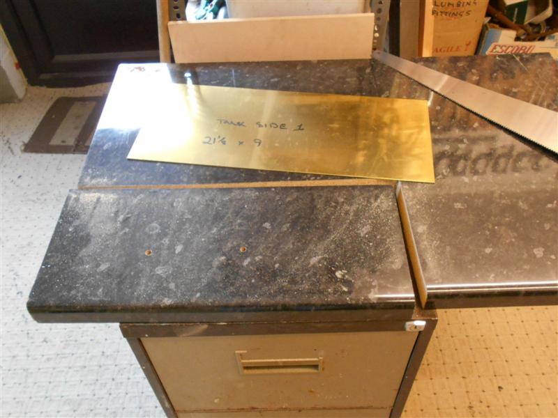
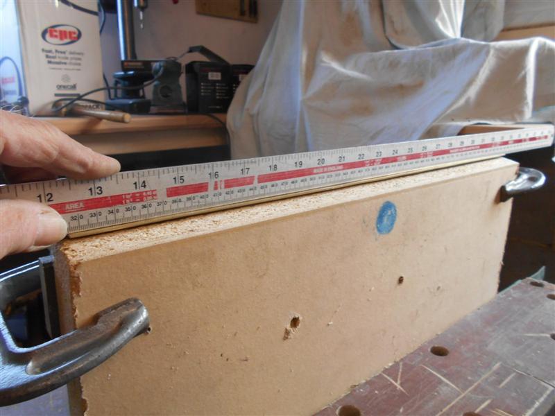
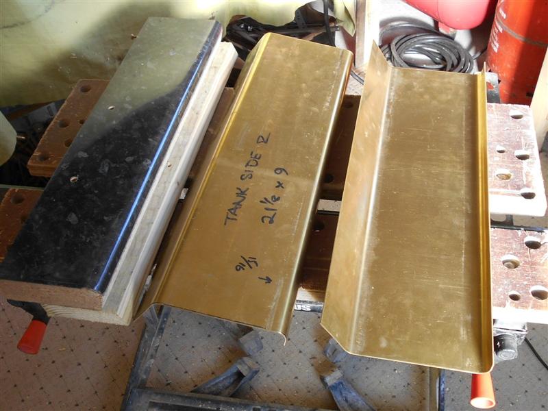
OK, as per my last post, apologies to those of you who may have seen this before. I actually made the tender sides in March 2016 and wrote them up about the same time. This year, I have done some more work on them on the warmer days when I fancied a break from the loft layout. Rather than flood the diary with a single very large update, I will feed the articles in about five days apart and we should be back in sync in about three weeks. The tender tank is constructed almost entirely from 16swg brass sheet and I had the main pieces guillotined from a 4ft x 2ft sheet by a local fabricators. The two tank sides need to have bends put in them and this would normally be done on a large folding machine or pressed to shape in a hydraulic press. I have neither and didn't want to have to make a large piece of equipment just to form four bends so decided to make a wooden former and bend them around that. The material chosen was a short length of kitchen worktop with a half-inch radius to the front top edge. Since this is specific to the one item, I cut the worktop a 1/4" longer and 1" wider than the tank sides.  Then, using an offcut of the same material, I clamped it up and put a bend in to find out just where to set the tank side on the former and to see how close to a right-angle I could get. I reckoned that I needed to set the panel 7/8" from the back edge and about another ten degrees undercut to the front edge. To achieve this I planed an angle on the edge.  Then I put my offcut back on the former and clouted it a bit more with my nice new rubber mallet.  I was happy with this so now I loaded one of the tank sides to the former with a decent-sized piece of support material clamped on the top, put the whole lot in the workmate and gently tapped the edge over, working back and forth along the panel to keep the bend reasonably even throughout.  Eventually, I reached the point where it wouldn't take any further set (springing off the former) and just kept gently tapping until I had a decent straight line at the bottom.   This was then repeated with the other tank side. The upper bend in the panels is at twenty five degrees from the horizontal and to form this I first had to reduce the size of the former and chose to saw it down to five inches wide. Then the offcut from earlier was clamped to the former with a half-inch spacer at the back and the metal tapped down until the twenty-five degrees was achieved. This was then offered up to the drawing to check the angle and to see what distance to set the rear spacing at.  As you can see, it's about 7/16" short so the spacing needs to be 15/16". I put a couple of wood screws in the back of the former and set them to this depth, in such a position that they would not foul the bend on the material. I also set another piece of timber, which I planed to twenty five degrees, at the back of the fomer to act as a stop.  This time, I also clamped a support bar to the part of the tank side that I would be hammering over because this should help keep the sides straight. However, I found that this was too restrictive and I couldn't get the material to bend so I went back to the freehand method and slowly worked the material down till it hit the stop.  And I now have two tank side sheets ready for the next operations which are to remove the surplus material from the top bent section and then drill all the holes - a heck of a lot of them.  Thanks for looking in. Steve |
|
barlowworks
Statesman
  Now finished my other projects, Britannia here I come
Posts: 878 
|
Post by barlowworks on Mar 26, 2017 16:56:53 GMT
Excellent Steve. The tender is the part that I shall tackle first on my brit when I start and watching how you and Jim go about it will be a great help. As a complete novice I believe every bit of information is a bonus.
Mike
|
|
|
|
Post by 92220 on Mar 26, 2017 17:37:47 GMT
A very handy thread Steve. I am working on my tender at the moment, and will soon be looking at the platework, so yours and Jim's threads make very handy workshop manuals!!
Bob
|
|