|
|
Post by springcrocus on Apr 25, 2017 7:01:19 GMT
It was mentioned by one member that the water gauge access panel was not often modelled on BR standard tenders, although I have found photos of a few examples, and I have decided to incorporate this feature on my own. There is no mention of this panel on my drawings but reference to a photo of the real Britannia and her tender gave me enough to get started. This is only on the left-hand side of the tender.  One of the problems with making this as a cutaway and fixing a panel behind the tank skin is the position of the fixings. Looking at the photo, it shows the screws, bolts, whatever they are, on the inner section of the panel, which requires something further below to fix to. The other problem is one of scale. My tank sides are from 16swg material which would represent the tender being originally constructed from 1/2" plate!. I decided to mill away a recess and incorporate dummy rivets which should look reasonably authentic after a coat or two of paint. I started by mounting the side panel on one of my general-purpose milling fixtures and supported the outer end with packing to dampen any vibration. 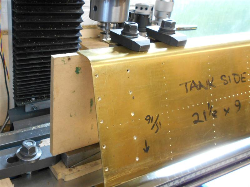 Using a 1/8" slot drill, I milled away the area to a depth of 15 thou with multiple back-and-forth passes and a final series of cuts around the periphery. The section was then given a quick rub-over with a fibreglass pencil to smooth out the tram lines. This was followed by drilling the fixing holes, which I worked out by scaling from the photo. It's not particulary accurate but close enough for this purpose.  To finish, twenty 3/64" copper rivets have been soldered in the holes, and the two eyes were appropriated from the dolls house accessories, part of our hook-and-eye door closers, also soldered in from below.  I completed these last Saturday morning and, looking at the drawings that Bob posted in Jims thread, it seems my dimensions aren't too far out, so I'm pleased with the overall appearance. Thanks for looking in, Steve |
|
|
|
Post by Cro on Apr 25, 2017 7:04:20 GMT
Steve,
So simple yet so effective! Love it.
Adam
|
|
|
|
Post by springcrocus on Apr 25, 2017 7:56:11 GMT
Steve, So simple yet so effective! Love it. Adam Thanks for that, Adam, and your words sum up my basic philosophy towards my approach to, and the writing up of, my work. Model engineering is not alchemy or rocket science and I hope my ramblings enourage those who are reluctant to start to give it a try. By showing how (relatively) easy some of the processes are, I would like to think that others would consider starting to make their own models, or construction projects of some sort. It seems an effective way to share knowledge, anyhow. Regards, Steve |
|
|
|
Post by Cro on Apr 25, 2017 8:11:39 GMT
Steve,
Completely agree and even techniques and processes that seem tricky can be made simpler by good, clear explanations like yours. I like to try and keep my work simple so that anyone can have a go and add that extra bit of detail without think its beyond them. If I can do it then others can!
Adam
|
|
|
|
Post by Jim on Apr 25, 2017 8:50:01 GMT
Doll's house suppliers are a handy source of detail parts too especially for carriages where the door handles, locks, coat hooks etc can be very easily included to create a nicely detailed scene.
Jim.
|
|
barlowworks
Statesman
  Now finished my other projects, Britannia here I come
Posts: 878 
|
Post by barlowworks on Apr 25, 2017 11:56:31 GMT
The idea of machining a 15 thou recess to represent the panel is genius. The way my mind works I would have cut the panel out and made another panel to fit 😏. It looks spot on to me ( filed away for future reference). Not to tell you how to do your build but a simple detail for not a lot of work is the lamp iron on the tender bulkhead. I think it would carry a red lamp for running light engine back to the shed, an excuse to use one of the exquisite 5inch gauge lamps that Mr Greenglade managed to get working for us.
Brilliant stuff
Mike
|
|
|
|
Post by springcrocus on Apr 28, 2017 21:47:27 GMT
A couple of people have asked me how I was holding the workpiece on the mill table because it wasn't clear in the first photo. Here is a view from behind the setup showing a piece of 4" x 2" box section that I milled up a while ago as a general purpose clamping fixture. It's effectively a glorified 1-2-3 block, square all round but not dimensionally accurate to any particular size. Clamps can go down the inside in this situation. Here, I'm getting the thing square to the table.  Hope that helps, and thanks for looking in, Steve |
|
|
|
Post by springcrocus on Apr 30, 2017 15:54:51 GMT
It's getting near the time to solder the bunker panels together so I have been adding any extra features while I can still lay the panels flat. The first of these are some guide rails behind the removable section to help hold this in place. 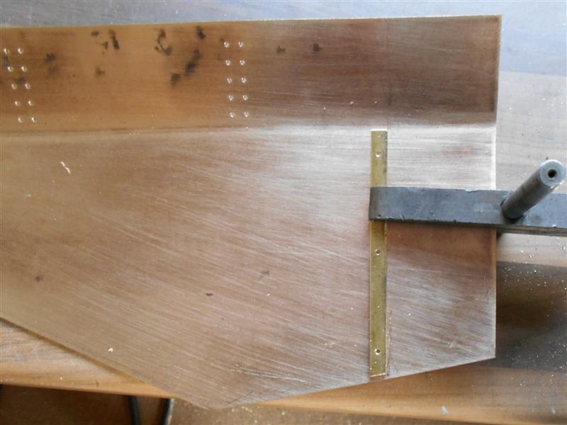 To help with keeping the bunker rigid and in shape while soldering, I have also made a range of brackets to enable me to screw the panels together. The brackets were all made from offcuts of the 16swg, with one hole drilled and tapped 8BA and then the bracket bent to the correct angle. The floor panel was drilled for 8BA clearance and countersunk to allow the screws to be recessed slightly. 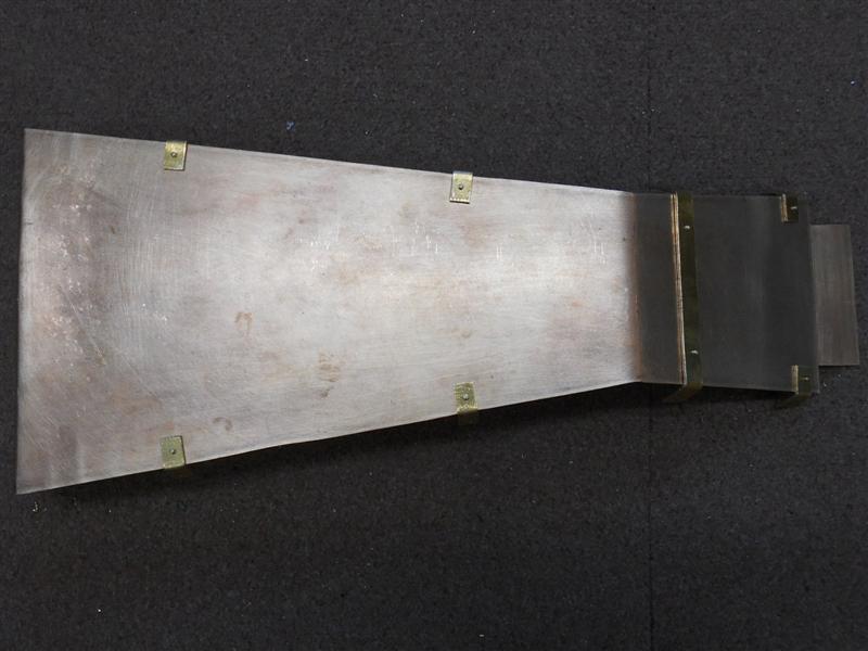 The bunker was reassembled inside the tank and the mid position of each bracket marked onto the side panels. The panels were then removed, an 8BA clearance hole drilled 1/4" in from the edge and the panel replaced in the tank. The other leg of each bracket was spotted through the respective panel holes and then removed, one at a time, and drilled and tapped 8BA.  Because I will be making a dummy coal tray for the top , I also made internal corner brackets for the rear of the bunker. These serve a dual purpose - holding the bunker sides in the correct position, and acting as resting points for the underside of the coal tray. They have been made with greater accuracy than the other brackets and are precisely 1/2" below the top. Other resting points have been added at the opposite corners and half-way along, making use of the rows of rivets visible on the outside. All the rivets in the end and sides have been fixed, as well.  Here is how it looks set back into the tank. I have also added the rainstrip to the rear of the locker section. The drawing calls for this to be 3/8" above the roof but Bob's drawing shows 3" full-size so I have reduced mine to 1/4".  I will wait a few days before soldering the assembly together, just in case I have overlooked something and need to do further work on any of the panels. Thanks for looking in, Steve |
|
|
|
Post by springcrocus on May 8, 2017 21:40:05 GMT
It seems that the smaller the part, the longer it takes to produce it. The lamp irons are my own interpretation of what is correct for the BR1 tender and have been made from some 20swg brass sheet. Four are required for the rear of the tender and I started by cutting two strips about 1.3/4" long and milled the width to 5/16" on the Cowells.  Over on the big mill, I made a small fixture to drop these into so that I could accurately drill the holes for the 3/64" rivets that I shall use to fix them with. This is a piece of 1" x 1" x 1/8" aluminium angle from the scrap box and will be re-usable when I make the lamp irons for the front of the loco, although the shape is a little different.  After drilling, they were marked out at 3/16" and 5/16" for the bend positions and then returned to the Cowells and the waist section thinned to 3/16". Unfortunately, I forgot to take a picture at this point but just some simple milling to reduce the width and working by sight to the scribed lines. Each one was then halved with a junior hacksaw, bent at the scribed lines and the sides and end dressed to a slight taper with rounded ends.  Also in the picture are the lifting eyes, made from 16 swg offcuts, and the lower tank-fixing brackets from 1/2" brass angle. It doesn't seem much for the weeks output but, at this time of year, the Head Gardener requires a larger share of my time than normal. All these parts will be fixed in place just prior to soldering which I hope to start next weekend. Thanks for looking in, Steve |
|
|
|
Post by Cro on May 8, 2017 22:30:36 GMT
Looking good Steve, nice little touches, will have the filter box plates in the post first thing Monday after collection this weekend!
Have you done the tender chassis yet or is this still to come?
Adam
|
|
|
|
Post by springcrocus on May 11, 2017 22:01:51 GMT
As I am trying to finish the rear panel of the tender, I decided to make the three curved hand rails next. Although I have bending springs, they are really only any use for the steam and water pipes that proliferate around the locomotive where accuracy of the bend is less important. The first job was to make a simple bending tool and this was made in a similar manner to a plumbers pipe bender, albeit a lot smaller. The two wheels are made from 5/8" diameter mild steel with a 1/4" diameter hole through the middle. A 1/8" wide form tool with 1/16" radius was used to form the groove, finishing the fixed wheel a touch below 1/2" diameter and the moving one a little larger.  Others have shown how to make these and I won't go into detail here, they are fairly simple tools to make. The wheels are mounted between two handles, spaced to suit the 1/8" dia material, set on a large flat plate and with a 1/8" hole to drop in a stop pin to trap the material.  After a couple of trial runs to determine lengths, I made the first pair from 1/8" dia brass tube, the idea being to tap the bore M2.5 and, after drilling a pair of clearance holes, pull them to the rear panel from inside prior to soldering. 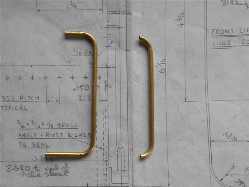 However, I found that my rather crude bending tool was damaging the outside of the tube as it pulled through so decided to make them from solid instead. This resulted in a reasonable shape with no visible damage but left the problem of fixing them to the rear panel. Turning a spigot on the ends was the answer, but not easy to hold in the lathe. So I milled them instead. My boring head takes 12mm tooling and, conveniently, I have loads of 12mm HSS end mills so one of these was loaded to the boring head. The carbide tools that I have for my boring head are totally unsuitable for the task in hand.  The thing to remember is that the cutter in not rotating as in CNC milling but actually acting similar to a turning tool in a lathe. Therefore, the "centre height" has to be set by adjusting the cutter in the boring head. Also, it is facing the wrong way and the mill has to be run in reverse to mimic the action of a lathe.  This next picture shows the cutter as it is rotating about the workpiece, hence the ghostly image, but shows the cutting in action. 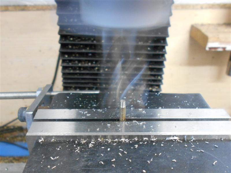 And here is the first of the handrails machined. I have reduced the diameter of the material to 2.5mm and will drill holes to suit in the rear panel, followed by soldering into place from the inside. The surplus material of the spigot can be trimmed afterwards, or left as is, there is only water space on the other side. 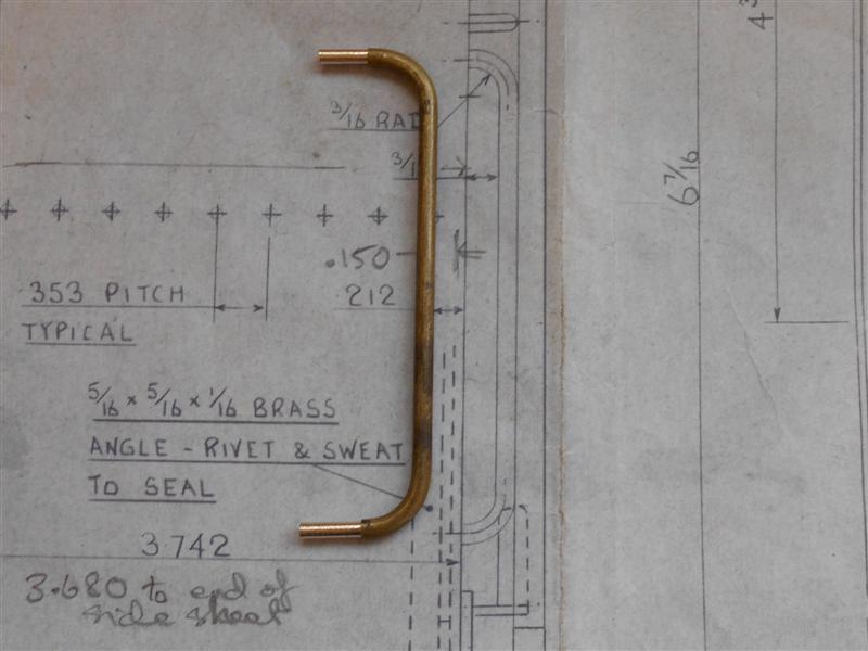 Thanks for looking in, Steve |
|
|
|
Post by arch1947 on May 12, 2017 1:22:28 GMT
Very nice work.
|
|
|
|
Post by Roger on May 12, 2017 13:55:38 GMT
That's a very clever use of a boring head, some proper lateral thinking going on there! Brilliant!
|
|
|
|
Post by jon38r80 on May 12, 2017 15:13:31 GMT
+1 to Rogers comment, I wouildnt have thought of it or dared if I had. Are you going to thread the stubs ant fix with a nut and a washer from behind , the reversew of your original idea. the washer would give a little local stiffness on the thin brass sheet.
|
|
|
|
Post by springcrocus on May 13, 2017 21:56:35 GMT
+1 to Rogers comment, I wouldn't have thought of it or dared if I had. Are you going to thread the stubs and fix with a nut and a washer from behind, the reverse of your original idea? The washer would give a little local stiffness on the thin brass sheet. It's not neccessary really, if you think about it, the tube needed supporting prior to soldering over the fixing (thinking, "watertightness" here) but the spigot on the solid bar is self-supporting so can just be soldered. The brass sheet is 16 swg, so fairly rigid, whereas Jim, for instance, is (I think) using 22 swg galvanised steel sheet which is quite a bit thinner although the inherent strength is similar. Heck of a lot cheaper, though.  I bought the brass sheet in more affluent times just to do this job. If starting again, I would think carefully about the cost. Regards, Steve |
|
|
|
Post by Jim on May 14, 2017 1:17:41 GMT
<abbr>...............</abbr>The brass sheet is 16 swg, so fairly rigid, whereas Jim, for instance, is (I think) using 22 swg galvanised steel sheet which is quite a bit thinner although the inherent strength is similar. Heck of a lot cheaper, though.  I bought the brass sheet in more affluent times just to do this job. If starting again, I would think carefully about the cost. Regards, Steve Steve is right, I'm using non galvanised 22swg BMS sheet for the tender sides and rear bulkhead on my tender though I did use gal steel or the bunker and front of the tender. As Steve says it was a heck of a lot cheaper  but I should add it was all that was available locally. Whichever material you use is up to you but as always proper care and attention are essential for the longevity of your model and its overall appearance. Jim |
|
mbrown
Elder Statesman
  
Posts: 1,793
|
Post by mbrown on May 14, 2017 11:12:42 GMT
I would be very wary of galvanised sheet. My Bagnall 0-4-2T had the platework made from 20g galvanised steel (I was very poor in those days!). It took paint beautifully - but after a few years the paint started lifting off in great bubbles. I had some correspondence with Bob (92220) on this site a few weeks ago about priming galvanised plate - it can be tricky.
Malcolm
|
|
|
|
Post by Jim on May 14, 2017 12:05:40 GMT
I would be very wary of galvanised sheet. My Bagnall 0-4-2T had the platework made from 20g galvanised steel (I was very poor in those days!). It took paint beautifully - but after a few years the paint started lifting off in great bubbles. I had some correspondence with Bob (92220) on this site a few weeks ago about priming galvanised plate - it can be tricky. Malcolm Galvanised iron as it's often referred to out here will certainly cause the paint to blister if not thoroughly cleaned first and in some cases even left in the open to weather for a while to ensure the soluble salts and any oils are removed. As in all painting, surface prep is vital for good long lasting paint adherence. Jim. |
|
|
|
Post by springcrocus on May 15, 2017 19:45:37 GMT
I have made the ladder rails for the rear of the tender from offcuts of the 16 swg brass sheet, and the rungs from 3/32" diameter brass rod. By now, you will all be familiar with my aversion to any hand-work and how I strive to find a fully-machined result. To get started I marked out the shape of the rails, which are 3/16" wide, using the vernier height gauge to scribe the lines on a single piece of material. I also marked the centre of the curving section with a dot punch and used a compass to scribe the curves. Although I will use the DRO to set cutter positions the markings, which are not very clear on the photo but easily seen on the machine, will only be used to confirm my postions are correct and any final hand-work.  The returning section of each rail, the part that sits on the top of the tender, was extended by 3/8" to allow for the bending of the mounting feet. This and another piece of material were stacked on top of a piece of MDF and the three items clamped square to the bed using the tee-slot packers for a quick alignment.  The long outer edge of the rails were set as the "Y" datum and the centre of the curved section was picked up with a point and zeroed...  ... followed by plunge-milling with a range of cutters to arrive at the final size of 5/8".  A series of 3/64" holes were drilled to take the rungs and a larger hole drilled in the extended section for fixing to the tender top plate after bending. When drilling into MDF, the hole is always tighter than the drill size because the MDF deforms away from the drill and springs back afterwards. Because of this I was able to press 3/64" rivets into each hole as they were drilled and the rivet was held firm in the MDF. 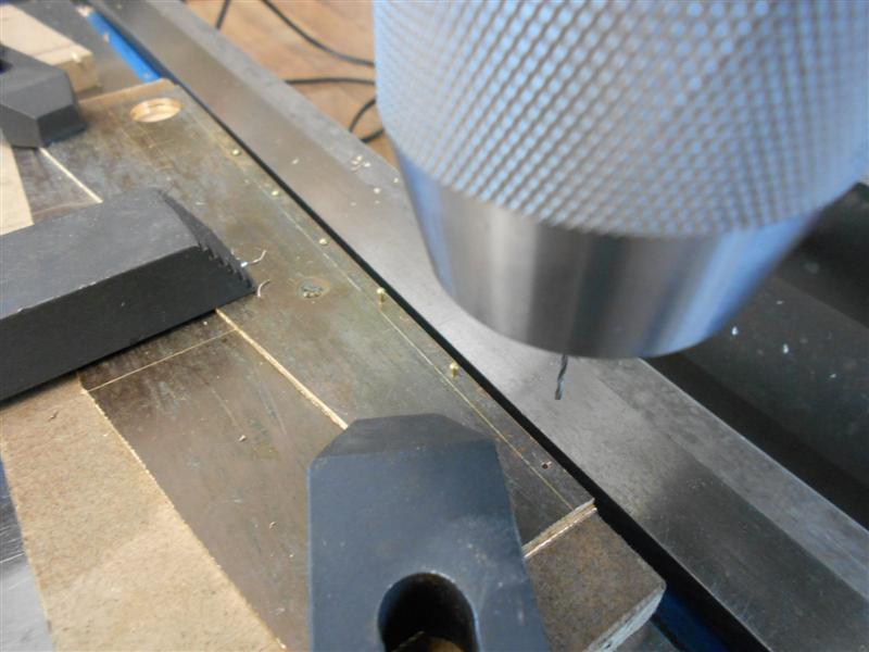 Changing over to a 1/8" slot drill, I then milled along the inside edge of the ladder rails until I reached the 5/8" dia hole. The cutter was set about fifteen thou into the MDF and the rivets held the material firm enough that no further clamping was required.  On reaching the X0 datum, I wound across to the other side and continued cutting the edges of the rails. The next picture shows the tool path that I took to free the rails from the raw stock.  After releasing the parts from the mill table, I am left with a small amount of hand-work to form the outside radius. 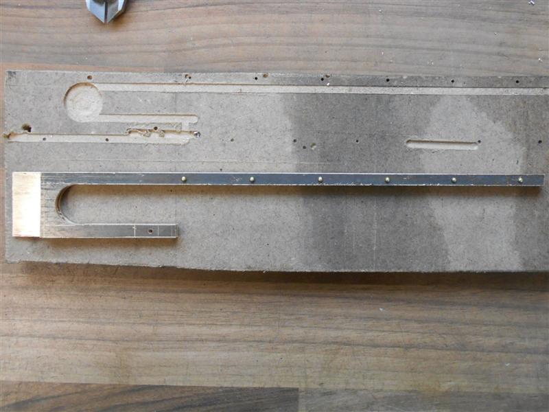 I shall clean these up and put the bends in the rail ends, then make the rungs and rivet them into the rails. Thanks for looking in, Steve |
|
|
|
Post by springcrocus on May 17, 2017 18:35:09 GMT
I have now cleaned up the ladder rails and put the top bends in. I have also drilled another hole in the bottom of each rail to mount an angle bracket for fixing to the soleplate. This feature is not clear on the drawing and missing in all but the plan view, nor is it dimensioned. I have made a pair of mounting feet from some 1/4" brass angle. At this point, I realised I had made an error and decided to instigate "Plan B". I had forgotten to allow for the thickness of the material when marking out and drilling the top mounting feet. So I cut them off level with the top of the tank and turned the offcuts into angles instead.  Also seen in the picture above are the rungs which are made from 3/32" dia brass with spigots turned to 3/64" dia at each end. The mounting feet were riveted on first. Then the rungs were assembled between the rails, held in place by elastic bands, and the spigots were gently peened into the countersinks on the outer sides of the rails. To complete, rivets were soldered into both the top and bottom mounting feet. These protrude about 3/16" below the feet and have been rounded off with a file.  Because I want my top plate to be removable, the ladder will drop into locating holes in the sole plate and tender top when on display but be easily lifted out for safe storage when in use. Thanks for looking in, Steve |
|


 but I should add it was all that was available locally.


