|
|
Post by Roger on Apr 11, 2018 7:02:18 GMT
Plus one on the raising of machine stands. My lathe is about 100mm higher than supplied and it's just about right for me.
The 'vice on a stick' solves the same problem with the bench vice when getting up close and personal with fiddly things that need to be close to the end in my nose when filing.
|
|
jem
Elder Statesman
  
Posts: 1,075
|
Post by jem on Apr 11, 2018 16:24:16 GMT
I build my own stands for lathes etc, but I put a piece of channel under my Myford back in the 70's , 200mm wide and about 60mm high, this not only made the lathe higher, but more importantly much more ridged, as I could shim under the lathe feet to get it turning perfectly true.
best wishes
Jem
|
|
|
|
Post by Oily Rag on Apr 15, 2018 22:17:34 GMT
Made a new chamfer tool to use in the little Cowell’s lathe, after parting off in the Myford I take the bolt/pin to the little Cowells and face off to the correct thickness and then chamfer the hex. Once I have all dials set production went smoothly. Then I milled the foot plate square, then cleaned the machines down and mopped the work shop floor and felt good about that. I detest working in swarf and dirt in the hobby room. The foot plate will be chopped and drilled as the design and parts are produced, including a big hole for the firebox. I am going to mount a block and temporary reach rod on the foot plate for setting up the motion. I am not sure yet how I am mounting the servos.
I joined the Ffestiniog society. (50 Quid) The plan is that in 2020 I will visit and volunteer at the Boston Lodge there for 2- 3weeks. It costs 5 quid a night to stay at the railway hostel. I have got to do it once in my life, at this most famous Welsh railway.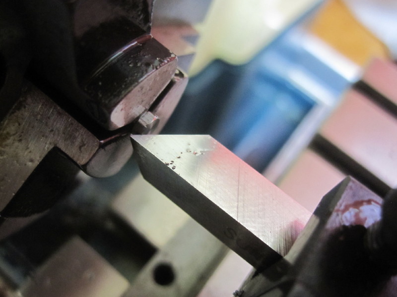 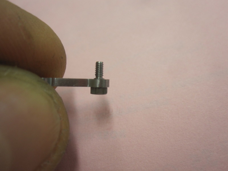 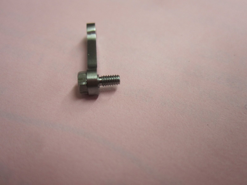 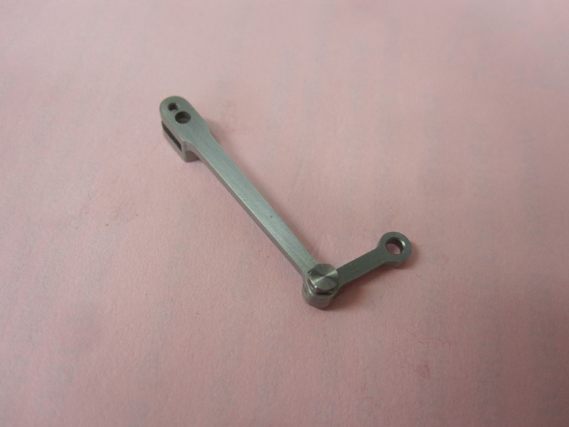 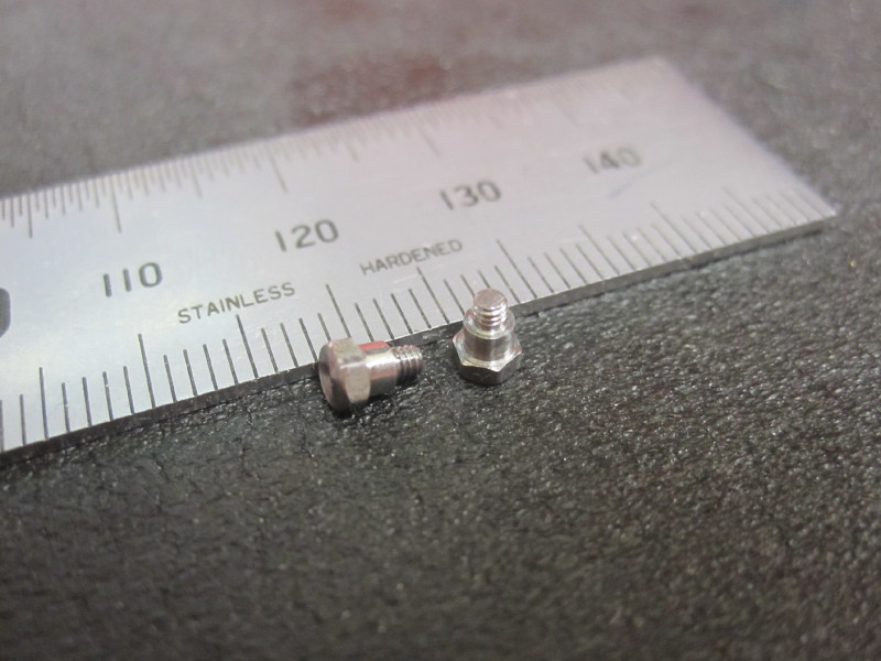 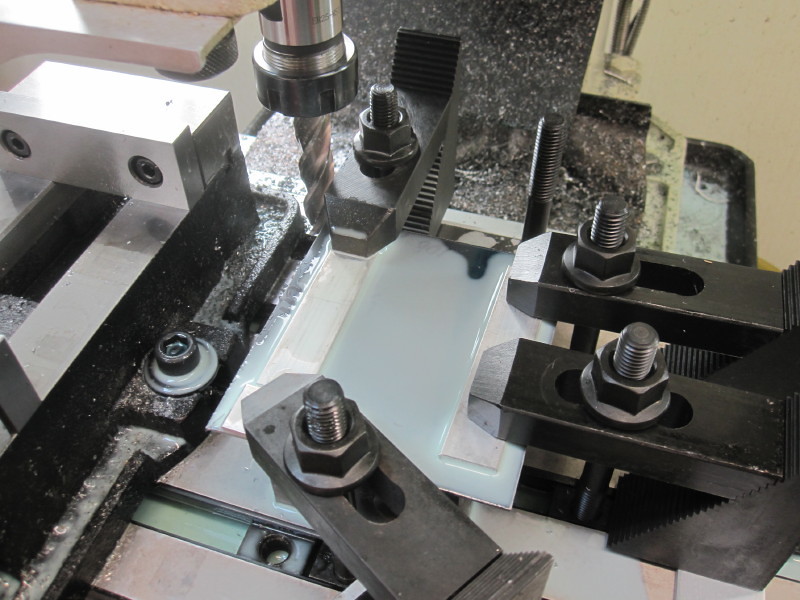 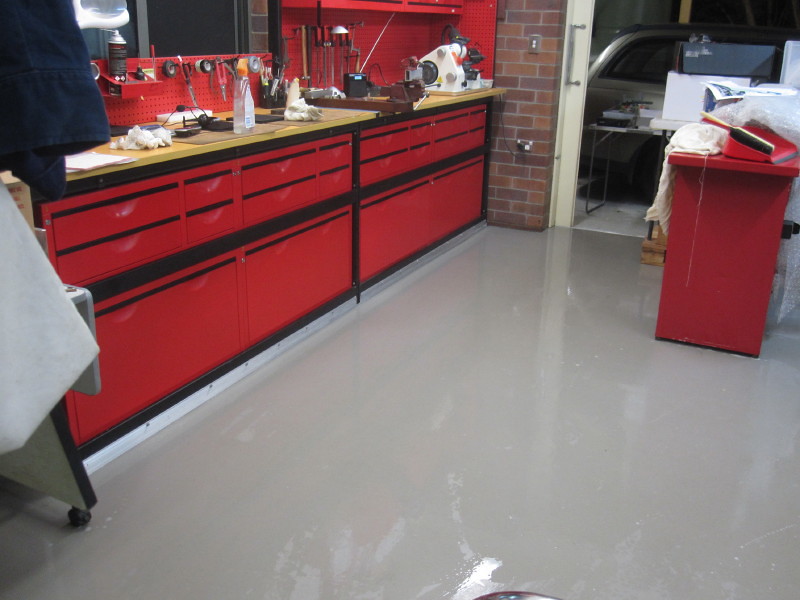 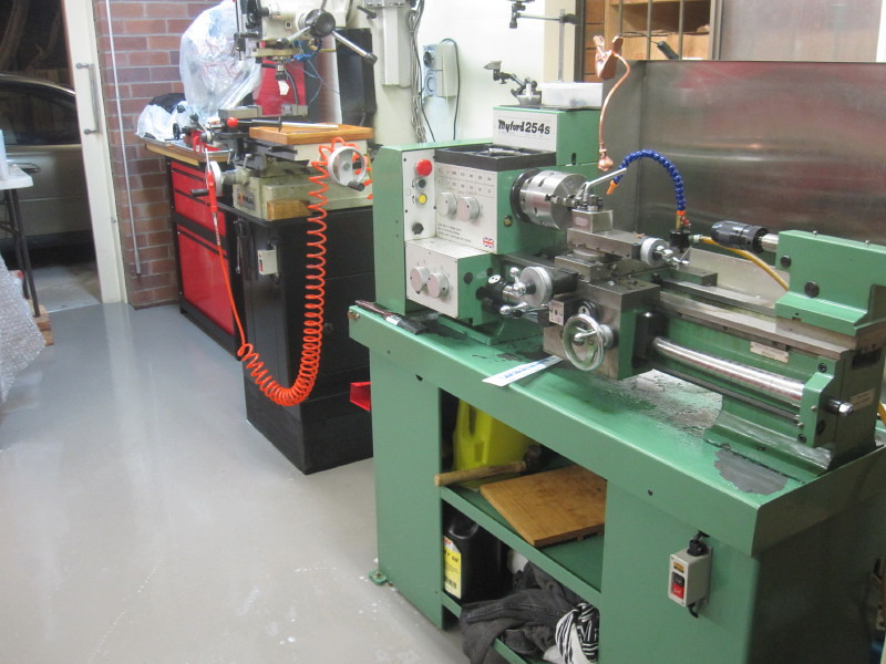 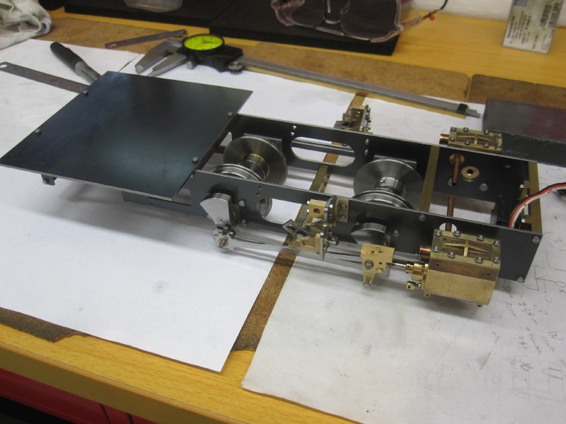 |
|
|
|
Post by Oily Rag on Apr 18, 2018 20:44:07 GMT
Finally at the stage of assembling more valve motion parts onto # 1.
Still to sort the eccentric rod , however we will be away for a few weeks for the "Handmade Bicycle Show Australia" so progress will be on hold. 
|
|
|
|
Post by Oily Rag on Apr 19, 2018 21:28:26 GMT
A few more parts fitted up. So far all is OK, I think I need to ease the fit of the valve cross head pin and there is a slight rub with the cosmetic bolt head on the cross head and combination lever. It was always tight here. I will be quiet for a few weeks as MAM and I are off for a few weeks and attending the Aussie hand made bike show.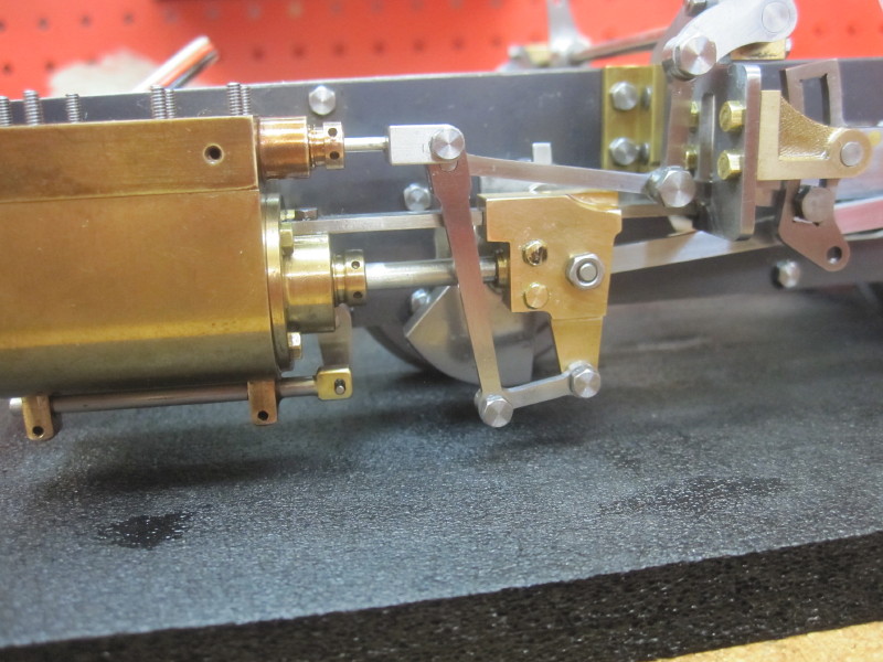 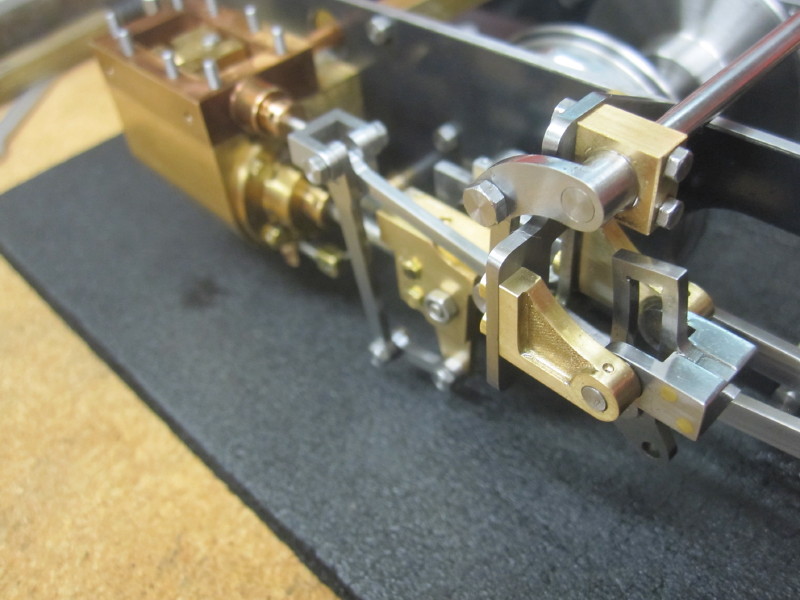
|
|
|
|
Post by Oily Rag on May 21, 2018 21:36:10 GMT
Working duplex gauges have been mentioned else where, Ohhhh, oh my, that will be sweet. QR's 3' 6" gauge is 1/8 in 5" gauge so a 7 1/4 Duplex should be feasible 
For our down under QR stock it would be for Westinghouse rather than vacuum. Only last weekend I was given the job of cleaning up two Duplex and a steam gauges for #967's rebuild.
so this subject of working gauges is of interest to me. 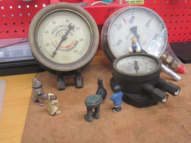 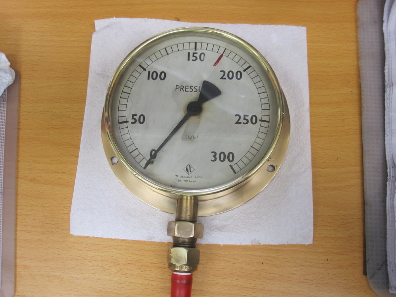
|
|
Lisa
Statesman
 
Posts: 806 
|
Post by Lisa on May 22, 2018 0:22:24 GMT
... QR's 3' 6" gauge is 1/8 in 5" gauge... Also the scale that works drawings were drawn to (the one's I have at least), which is rather convenient. |
|
|
|
Post by Oily Rag on Jun 3, 2018 1:17:54 GMT
Made a temporary reverser stand and completed the reach rod and pins. I am using this to confirm the eccentric rod lengths. Working on the eccentric rod drawings now.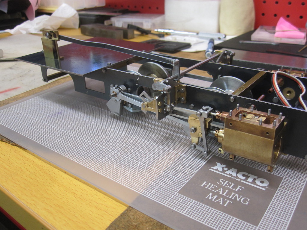
|
|
|
|
Post by Oily Rag on Jun 5, 2018 22:19:00 GMT
When one reads texts describing valve gear setting by many published "designers" I cannot help but think their descriptions are vague and brief. An easy to follow detailed described method that is in a logical sequence seems to be lacking ATMCO. (according to my current opinion)
One text says, "clamp the expansion link" No mention how you clamp it, considering it's size and shape and allowing the radius rod to move and be able to check measure the eccentric rod centres.
Any how I gave it some thought and then made an adjustable clamp last night for the expansion link so I can check the eccentric rod length that should be 46.08mm as per the drawing if the stars and planets align.
I will see if this clamp works as intended tonight.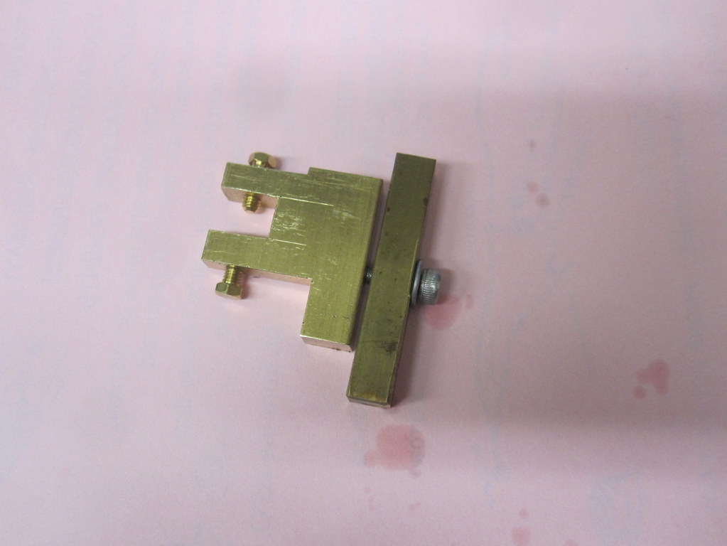
|
|
|
|
Post by Oily Rag on Jun 7, 2018 20:58:53 GMT
The clamp worked a treat. I intend to make an adjustable Eccentric rod to get the between centres dimension with more accuracy then fumbling with verniers with attached points and or dividers. Using dividers is fraught with peril ATMCO.
I did some chicken scratching drawings for this device but as much as I want to get stuck into making this tomorrow, I am off tomorrow to do some diesel driver training at the Mary Valley Rattler. 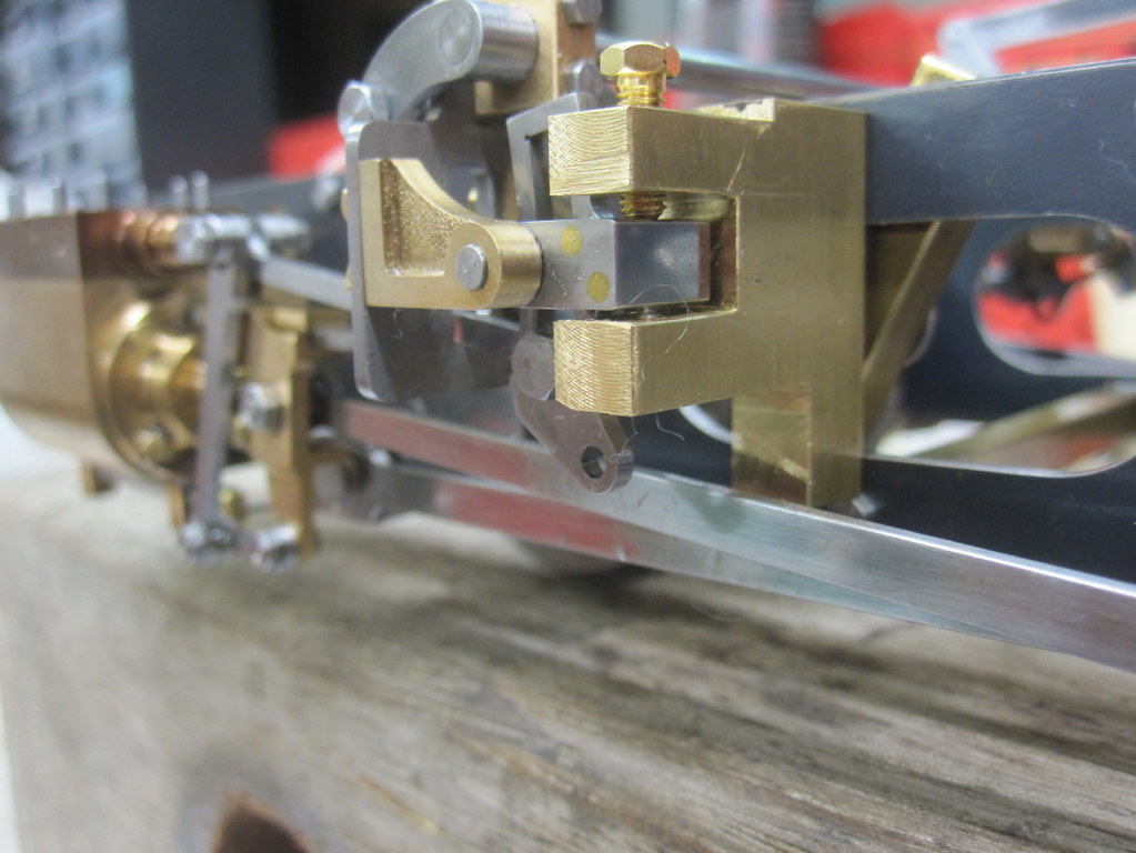 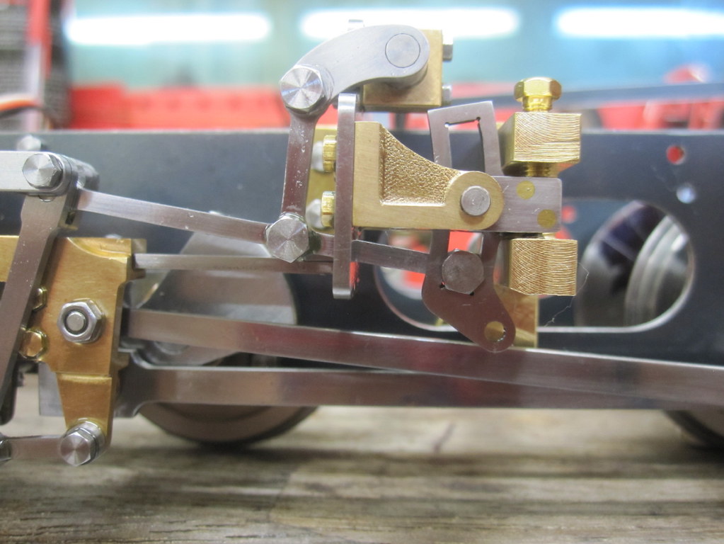 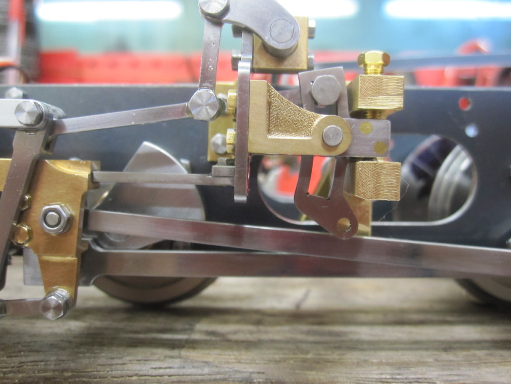
|
|
|
|
Post by Oily Rag on Jun 10, 2018 20:30:10 GMT
Sorting back and front dead centres 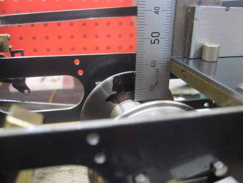 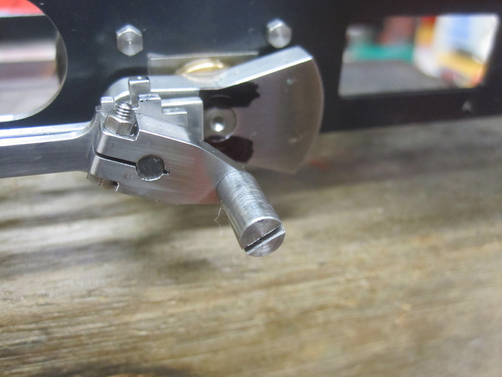 Adjustable eccentric rod in action. It seemed to work OK. 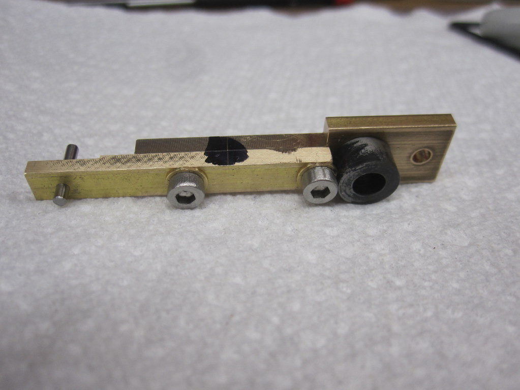 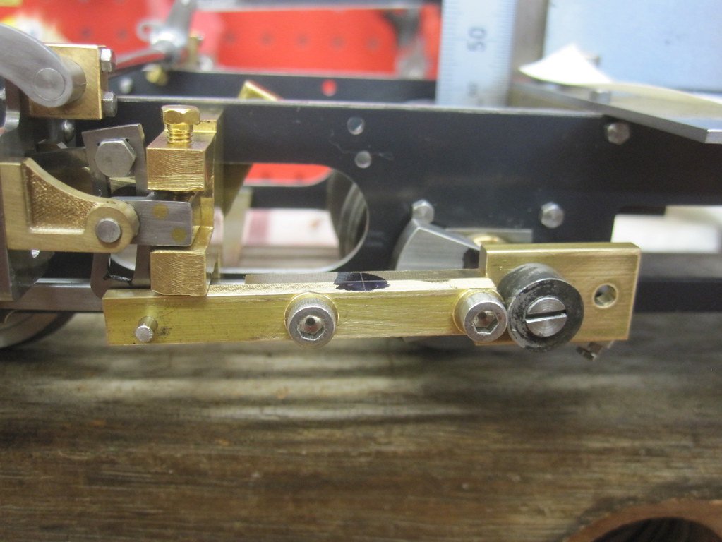 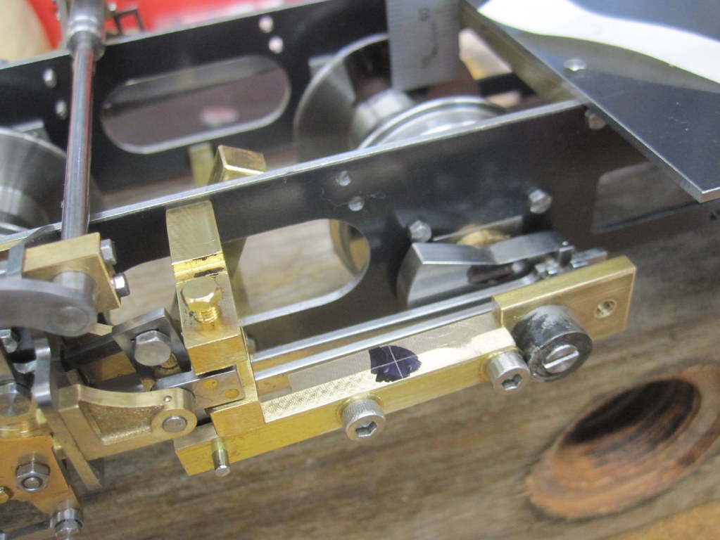 Measured then taken to the mill and DRO. My eccentric crank (return) seemed to be running on a bigger radius than the drawings, was to be 7.57mm but I have 7.90mm and the eccentric rod length is + .10mm than the drawing. I had allowed for the eccentric rod inclination in the crank setting. I will go with this and see how it all goes. The left hand side eccentric rod is underway. Getting closer to a test run on air. 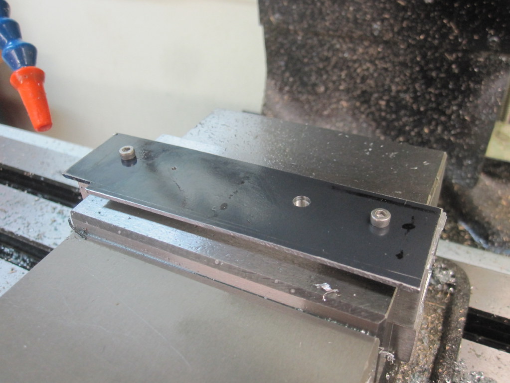 |
|
|
|
Post by Oily Rag on Jun 11, 2018 21:39:46 GMT
The left hand eccentric rod is underway.
Making yet another set of filing buttons.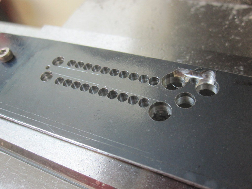 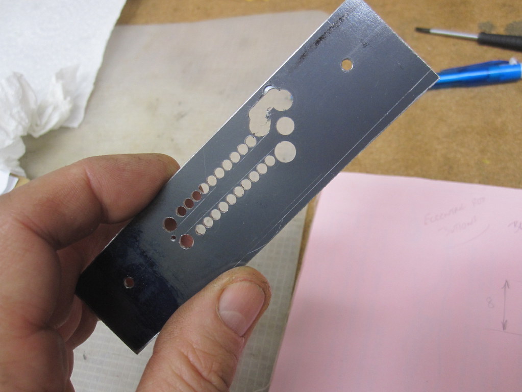
|
|
|
|
Post by Oily Rag on Jun 18, 2018 22:01:56 GMT
Sanded off the left hand E-rod and made its bush. That is all I got done last night.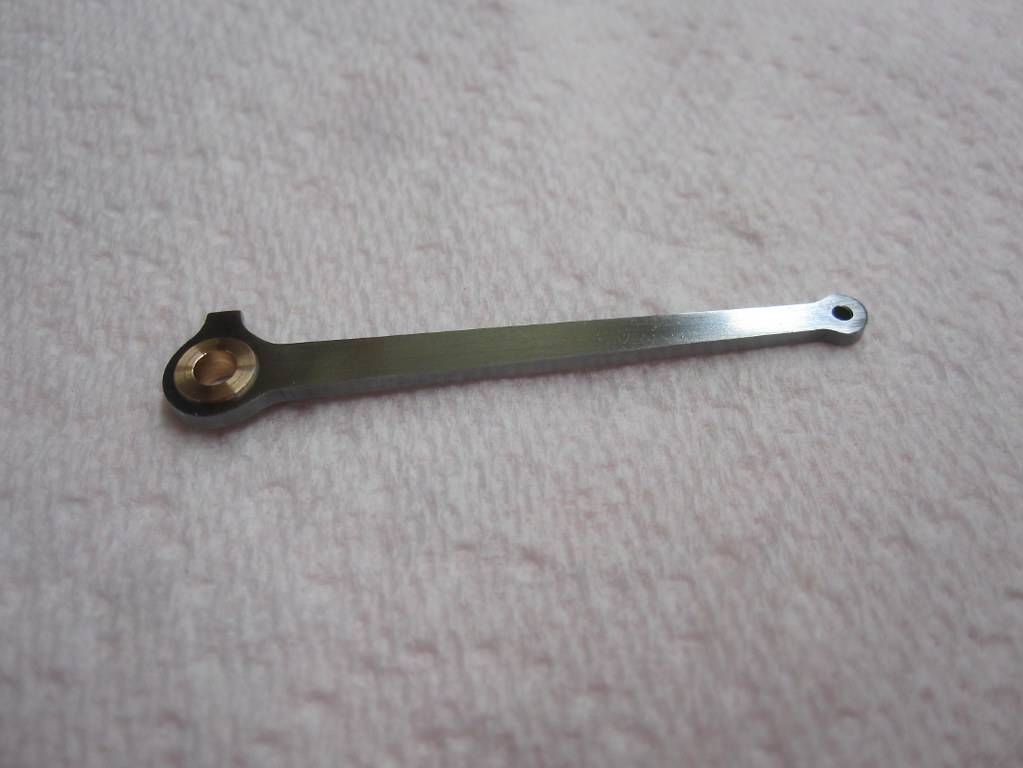
|
|
|
|
Post by Oily Rag on Jun 19, 2018 22:17:08 GMT
Nothing to report , just made another bush last night and started on some pins however these visited our driveway yesterday arvo. 900kg of rods for the rebuild of #967. They might be coming back for me to give them a clean up after they been through the setting up process. 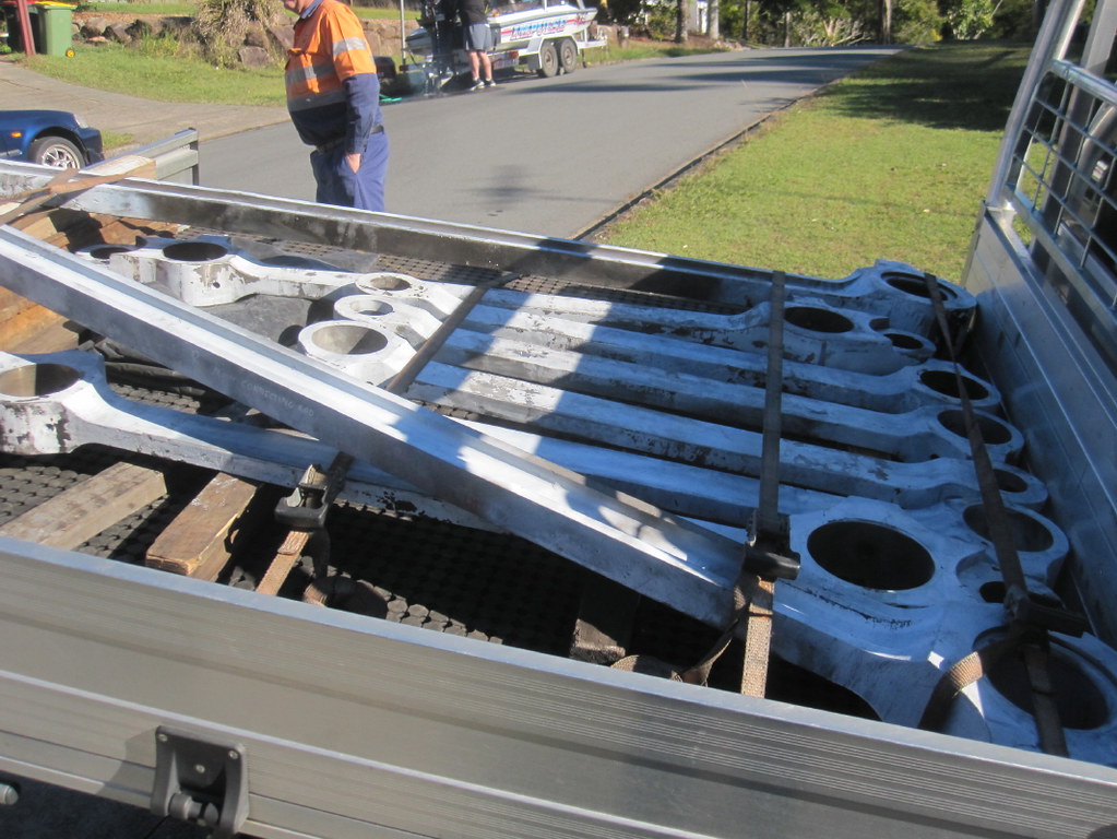 |
|
|
|
Post by Oily Rag on Jun 21, 2018 21:25:04 GMT
From Myford to Cowells, making more pins for the little choo choo
I seem to making incremental steps to getting to the air stage. 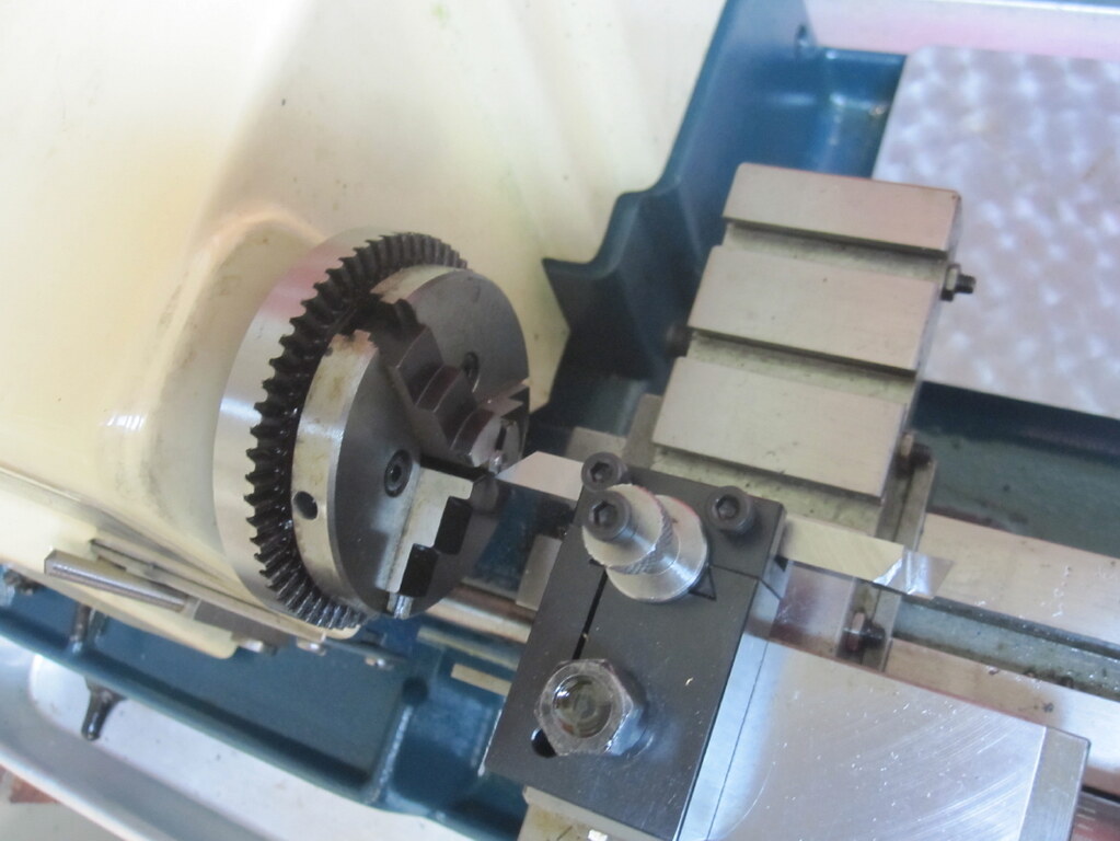 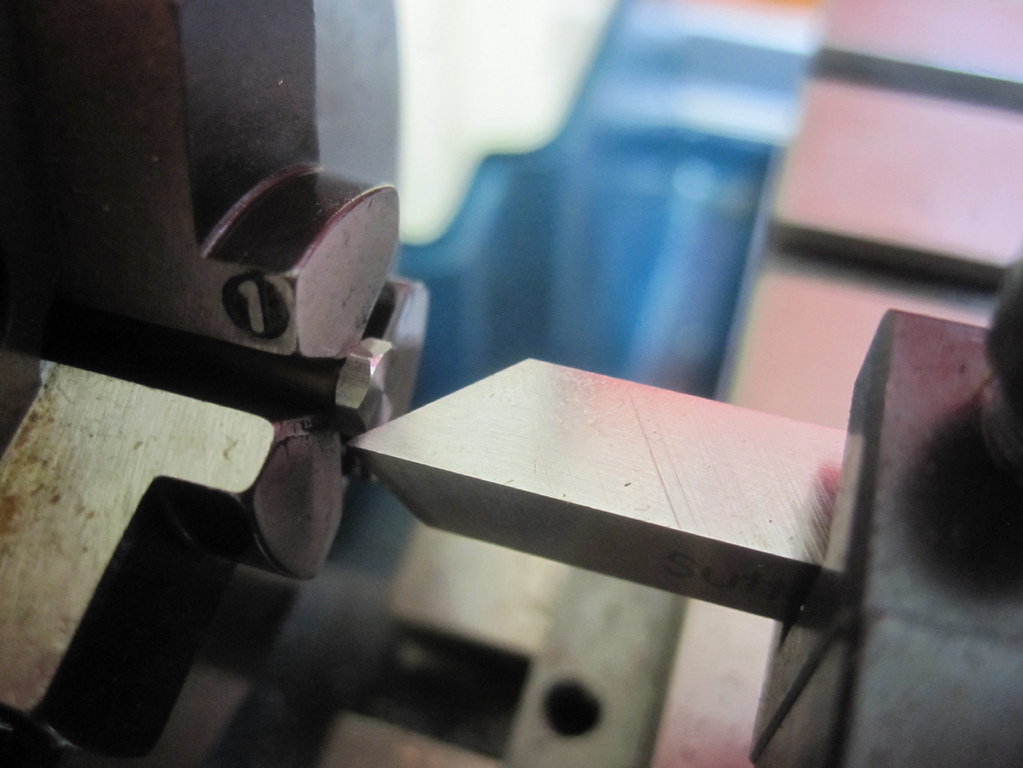
"Get the Cherry Red out and case harden these little fellas, off you go lads"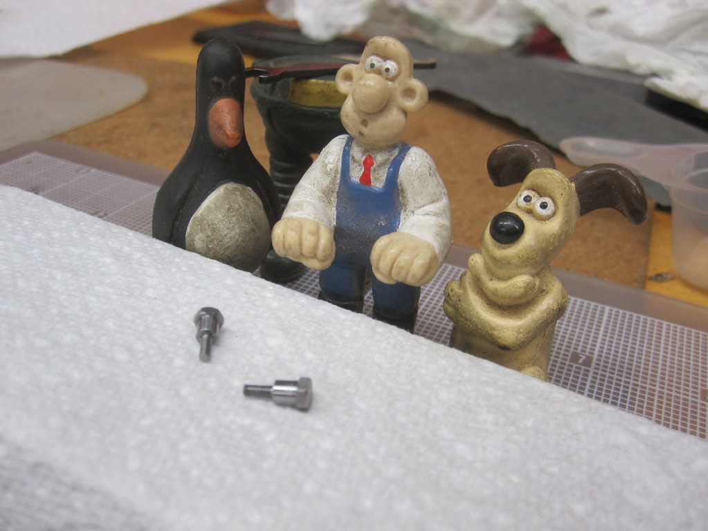 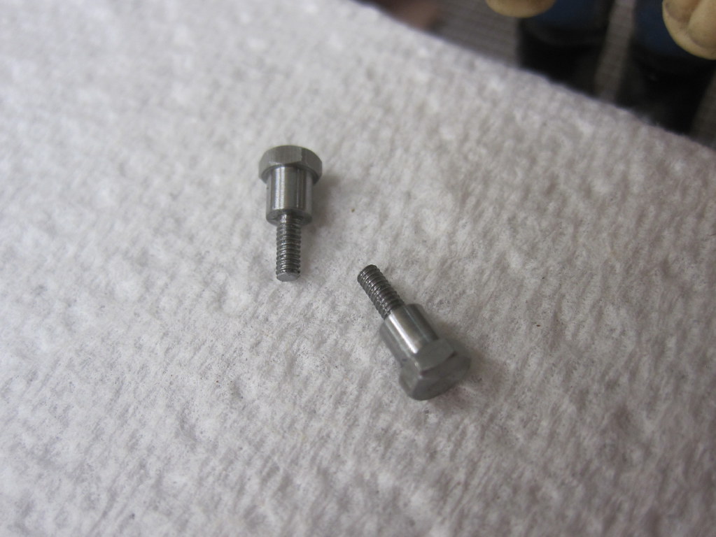
|
|
|
|
Post by 92220 on Jun 22, 2018 7:57:01 GMT
That's all some very nice work Darrell!
Bob.
|
|
|
|
Post by Oily Rag on Jun 23, 2018 23:10:54 GMT
That's all some very nice work Darrell! Bob.  |
|
|
|
Post by Oily Rag on Jun 26, 2018 2:49:28 GMT
The last pair of motion pins done last night. YAY!
Oh oh, I feel a sneeze coming on. Fear, fear of losing the evenings work on the Myford and Cowells. A pair of eccentric rod to links pins. Just the R/H e rod to do and then I see if this all will work as hoped.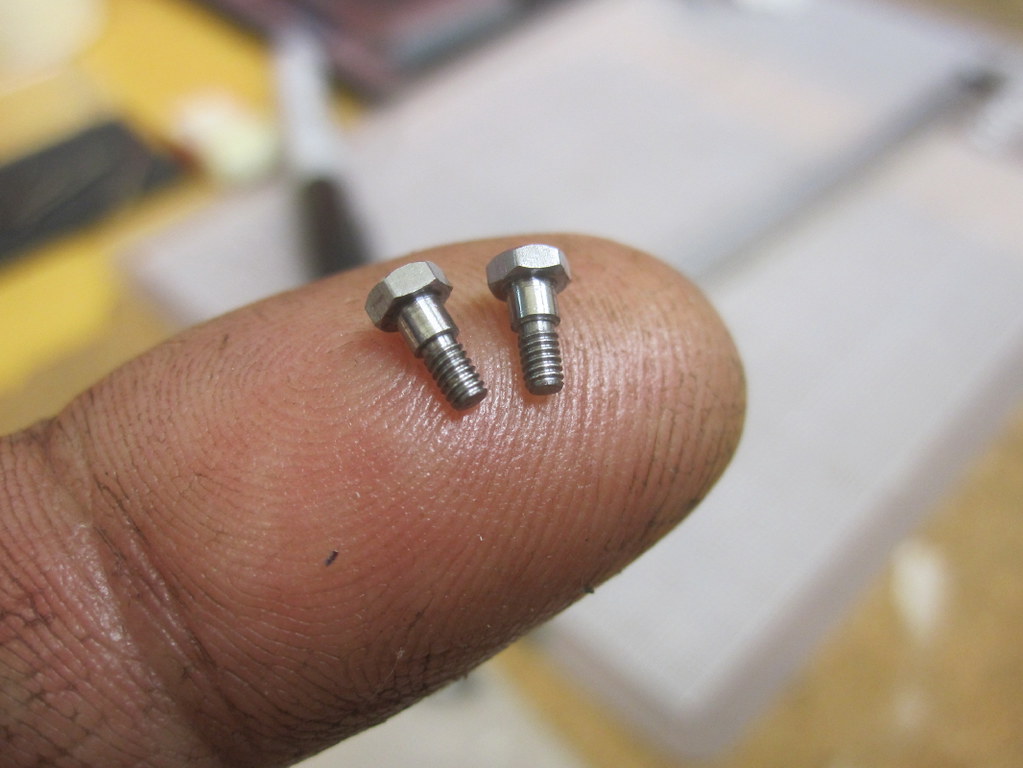
|
|
|
|
Post by Oily Rag on Jul 1, 2018 21:32:34 GMT
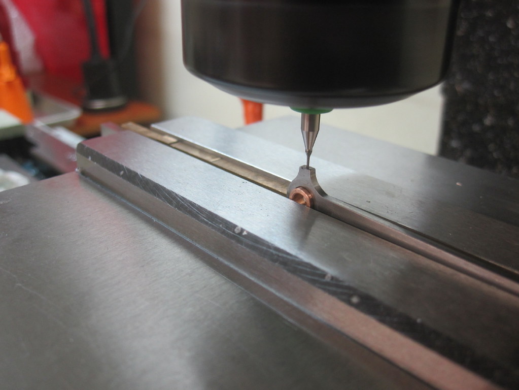
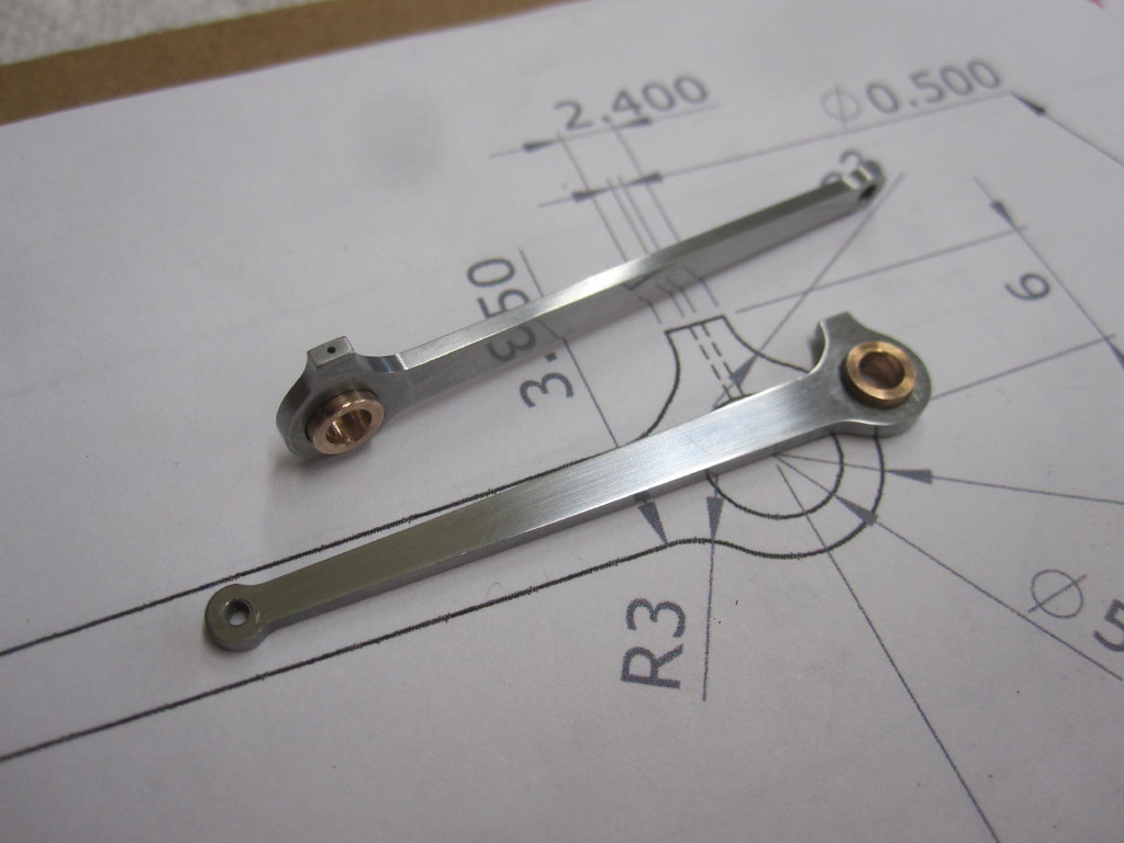
The other eccentric rod was completed this week.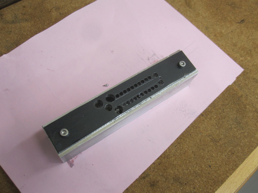 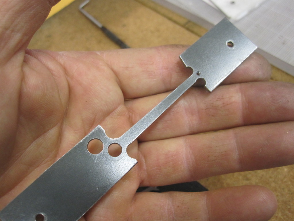 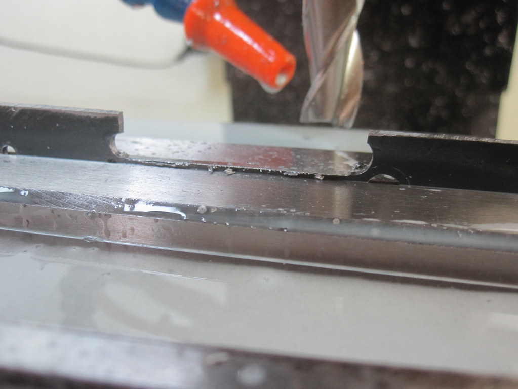 .50mm Oil holes are next. They are just for kicks and giggles but they make the rod bosses look the business. .50mm Oil holes are next. They are just for kicks and giggles but they make the rod bosses look the business.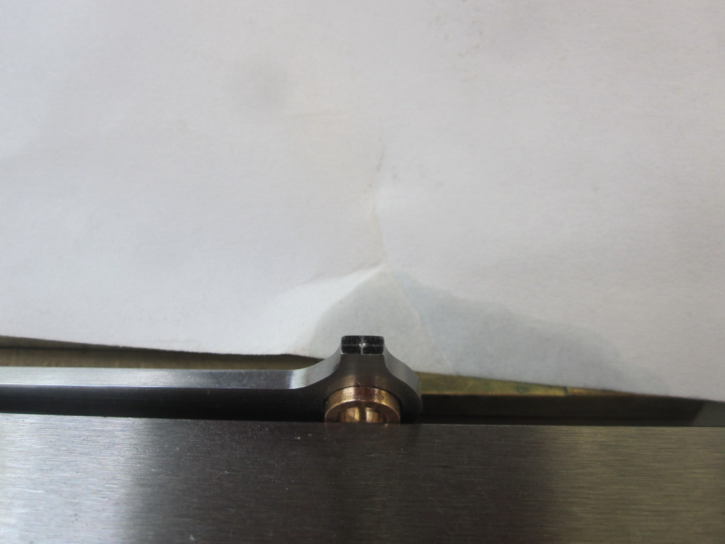 Carbide PCB drill trick Carbide PCB drill trick
|
|
|
|
Post by Oily Rag on Jul 1, 2018 21:49:37 GMT
I got DAG Brown's injector book out. Looked at his method of making olives etc. I decided to try this in a reduced size rather than the compression fittings that Brian Wilson mentions. There are also mistakes with the steam T in the book and much vagueness with the 1/8 steam supply tube, I drew up some olive fittings to try out and then to the Red Room I go. When these are completed I can finish setting up the motion and give the test run on air. It is all a bit stiff. It might be Kero lubrication till all runs as it should. Fingers crossed. I have never been here before.
These are the first olive steam connections I have ever made.
Ground a piece of HSS for the parting of the olive and a silver steel 60 degree D bit for the cone. 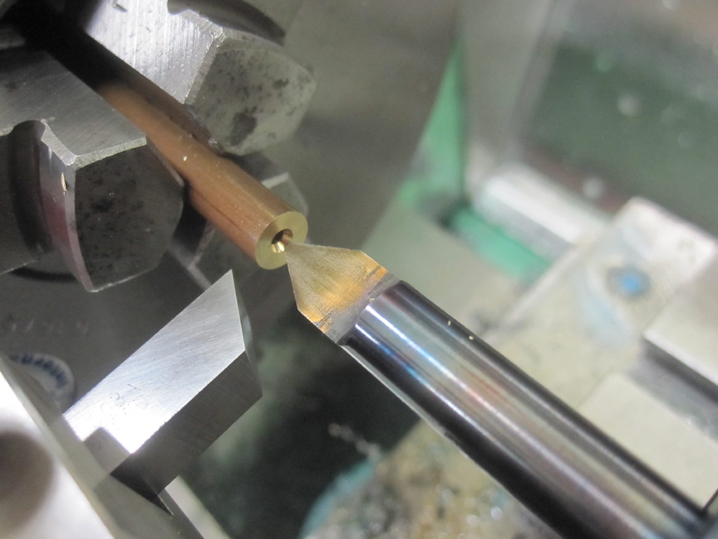 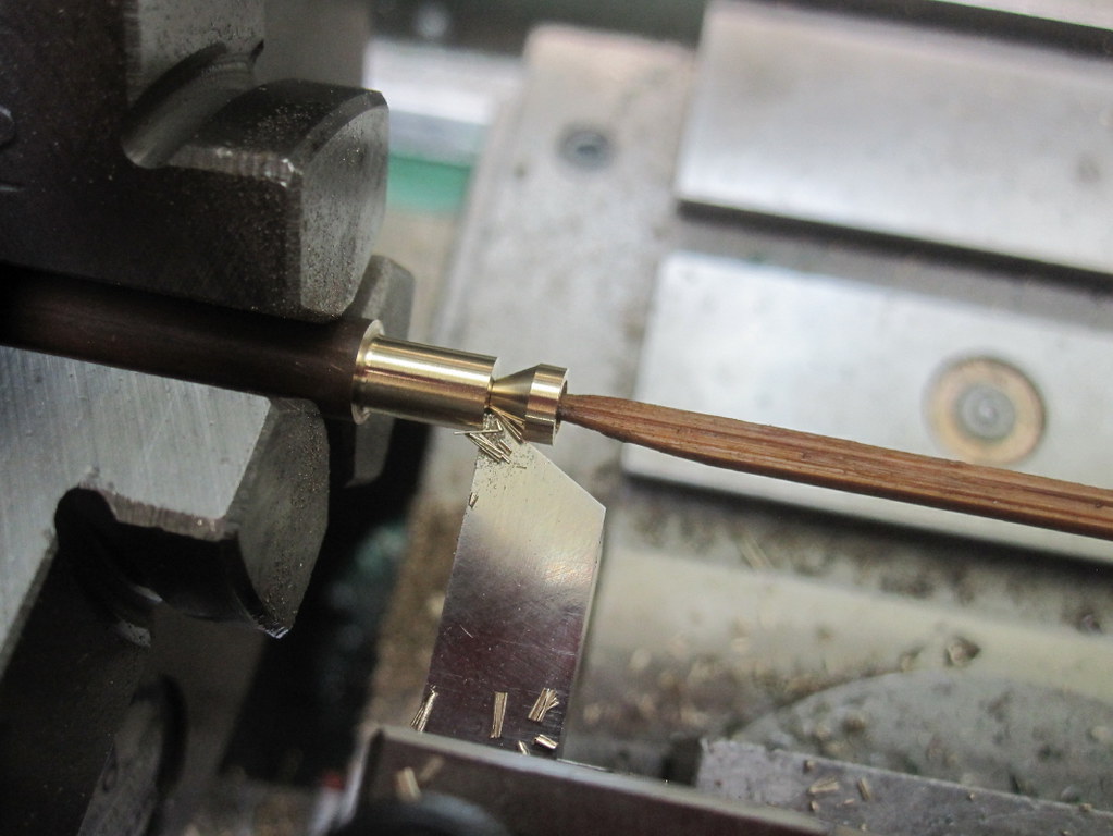 Silver braze the parts. Silver braze the parts.
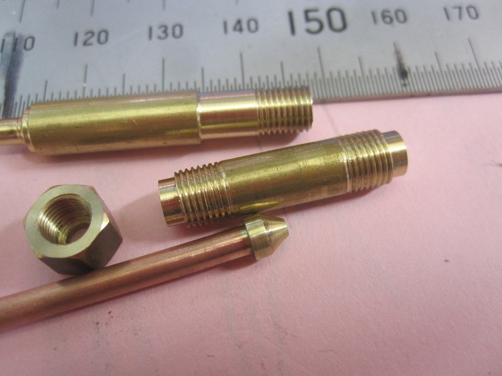 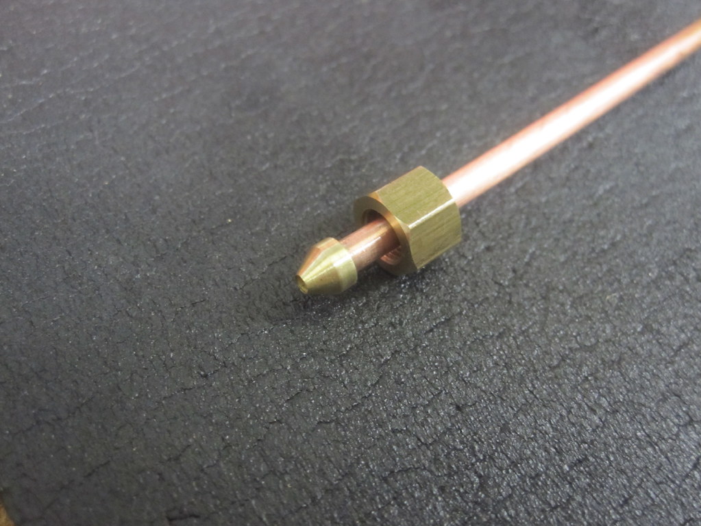 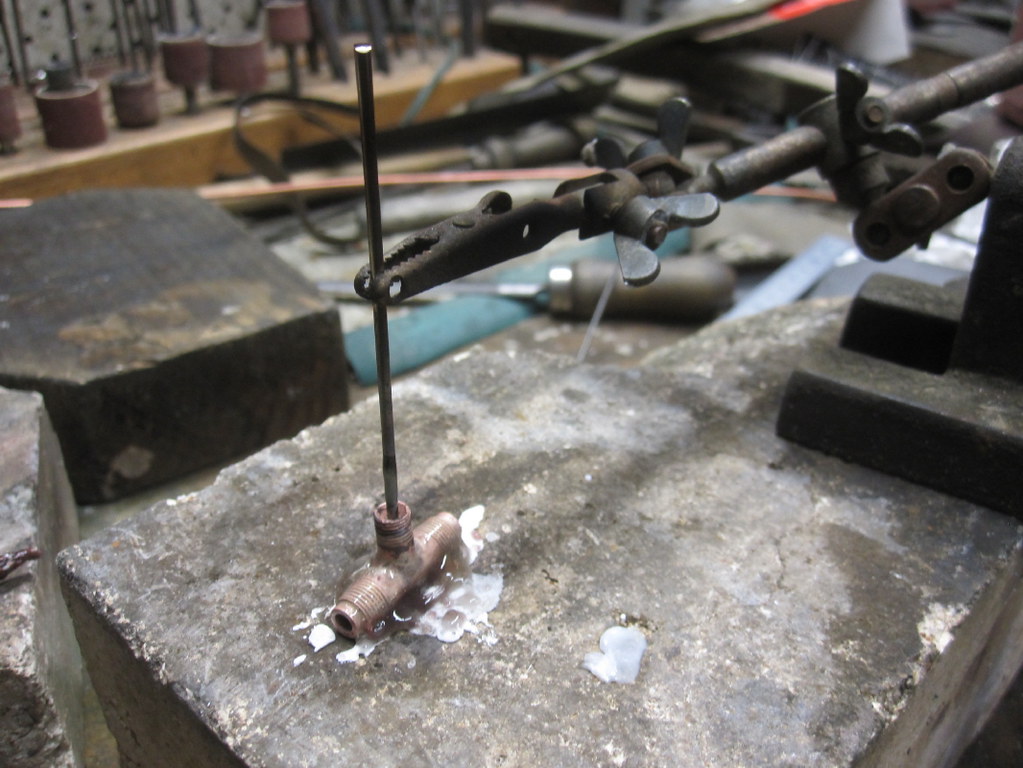 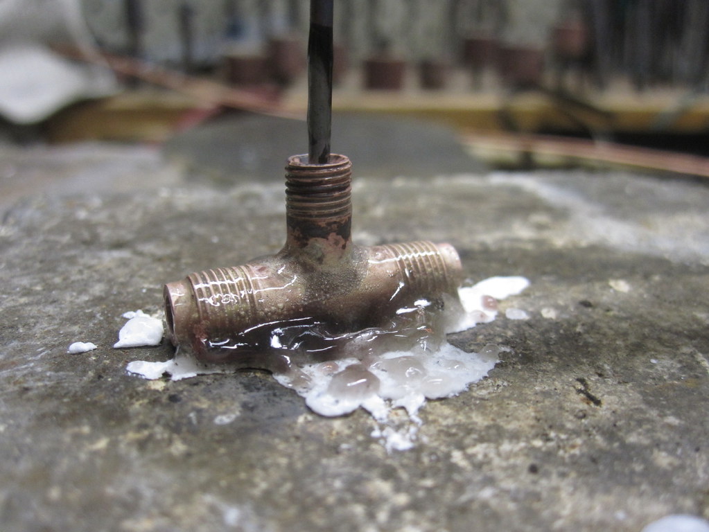 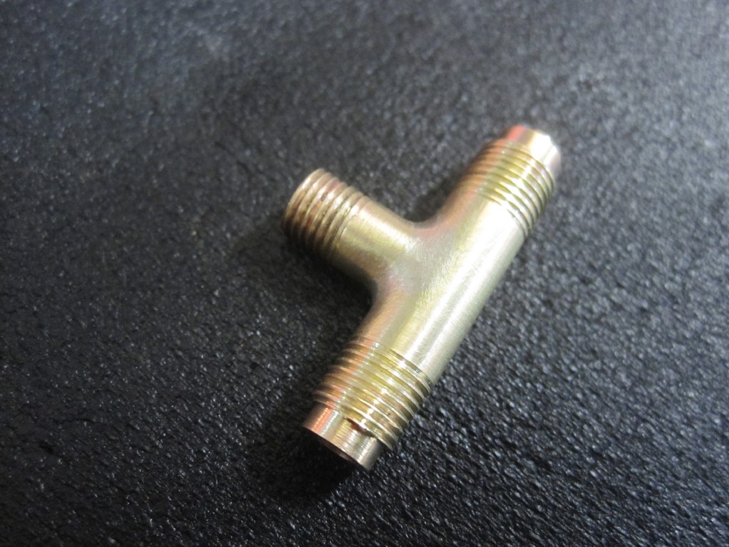 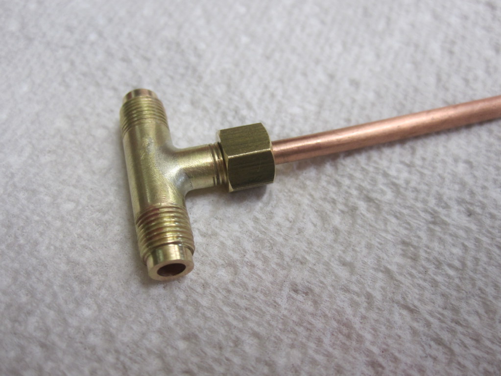 A couple of more nuts and I am done here. A couple of more nuts and I am done here.
|
|