|
|
Post by Roger on Mar 21, 2016 20:18:15 GMT
I thought I'd put this on a separate thread because it's of limited interest. A few of you are already using 2-1/2D machining, ie 2D profiles with a series of steps, so this is the next step. Before we start, it's worth pointing out that this is a last resort for machining anything because the time it takes is prohibitively long. In other words, if you can machine it any other way, then do it that way. Even if there are 3D elements to a shape, don't assume that you therefore are better off machining the whole thing as 3D. The dual safety valve I machined recently was done with a mix of 2-1/2D and full 3D, just to get the machining time down. So what I'm using is Geomagic Design with the Mecsoft CAM module. For all practical purposes, Geomagic Design is the same as Cubify. I presume you can use the same CAM module with that. Anyway, you probably will have different software to me, so we're more interested in the general ideas and reasons for doing things in a particular way. I usually show you just the models, but we're now going to take a step back and show the whole environment and how we steer that towards generating useful tool paths. Let's get started. This is what we're going to machine. It's got holes in it, and several simple shapes that are blended with fillets that results in something which is very difficult to machine with traditional methods. If you look at the Design Explorer pane on the left and you can see there are a series of steps that build the model from the part that says 'Features' onwards. I name these elements as I go else they're just called Sketch1 etc and you can't follow what you're looking at. Take the feature called 'Body'. That's just a circle at one end of the large body diameter. Above it is 'Extrusion<4>' which is what stretches that out to be a cylinder. That's all there is to it. If you look at feature called 'M4.5 tapping size', that's just a circle on the end of the body. The line above it is 'Extrusion<19>' which cuts out a hole to the required depth. If any of those are expanded then you can see more detail about them but we won't go into that here. The reason I'm pointing this out now is because we're about to change what's being used to make up the model. We don't want any 3D paths trying to dive into holes and causing problems. We'll add any holes later in a more simple way. As it happens, the holes probably won't cause any problems for us because they're on the sides, but I'm going to remove them anyway because it's good practice. 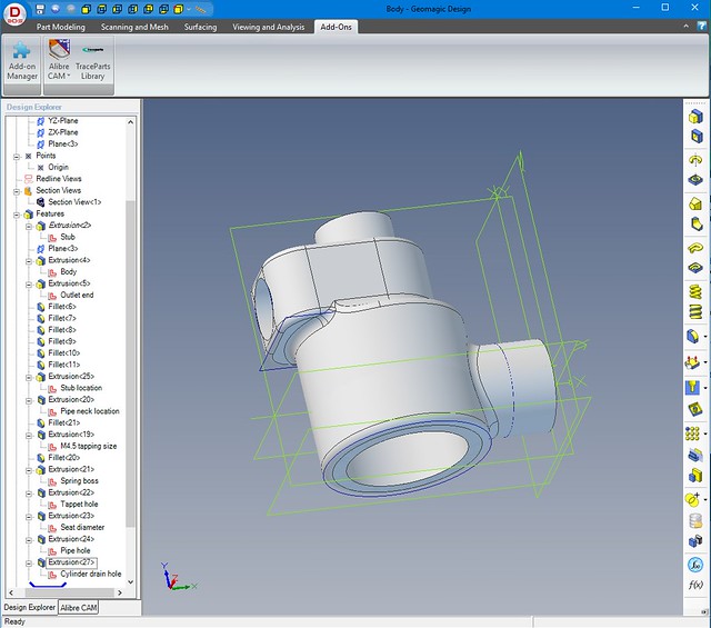 Starting point model Starting point model by Roger Froud, on Flickr So this is the same screen, with the exception that I've dragged the blue 'dog bone' shape up the list of features in the Design Explorer. I've made sure that all of the solid parts are defined first in the list, and all of the holes are defined at the end. This isn't always going to be the case, so you need to rearrange things so that it is. You can just drag any of the features up and down the list at will. The program isn't entirely stupid though, so if you decided to drag a hole that's in something that comes later in the list it's going to show that as an error. It will just put a cross on the feature that it can't resolve. So you can see that now all the things below the 'dog bone' are greyed out and that they've vanished from the 3D model. This is the starting point you need to get to. 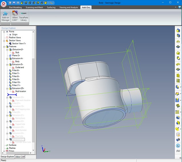 Now you can see that I've switched away from the Design Explorer tab to the Alibre CAM tab. This is the CAM module that will generate the G-Code to drive the machine. If you look at the model in the background, you can see there's a green plane with X/Y indicated on the corner. The model was deliberately created so that the shape was orientated this way. That's because it's going to be machined from the top surface you're looking down onto now. I've called up the Machine Coordinate System dialog so that I can tell it where the zero for machining purposes is located. On more expensive software you can machine the part in any orientation, but that costs a fortune. To get around that limitation, I have to think ahead about how I'm going to hold it for machining right at the start. As it happens, the zero for machining is at the origin of the model too. That's not an accident, I drew it that way by starting with the stub on the right which is where we're going to have the stock going into the rotary table. So you can now see the triad (X/Y/Z symbol) pointing at the +ve direction of each axis. It's sitting at X0Y0Z0 with X+ to the right Y+ away from us and Z+ heading up. That corresponds to the coordinate system of most milling machines. I could have put that on the LH end of the model, it doesn't really matter as long as we can set the machine to that point at the start of the operation. What does matter though is that the Z-axis is at the centre of that spigot. That's because this is a symmetrical part and I want to mirror the G-Code when the rotary table is turned 180 degrees to present the other side to the top. If this point is at X0Y0Z0, then changing all the Y+ to Y- and vice versa saves me having to create the program for the other side since it's identical in every other way. 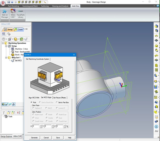 Setting the machine zero Setting the machine zero by Roger Froud, on Flickr Step 1 by Roger Froud, on Flickr Anyway, that's enough to be thinking about for the moment. Next, we'll decide on the stock we're going to use and how to tell the software where that is. |
|
|
|
Post by Roger on Mar 21, 2016 21:33:41 GMT
I still find this a bit mind bending, so don't be surprised if this isn't very obvious. The idea is a simple one. You tell the software how big the stock is and where it's located. When you tell the software to rough out the shape, it will remove all of the stock you've defined except where the model it inside it. So far so good, but setting this up is not the most intuitive process. It's not helped by the fact that the software only allows for rectangular stock, and I'm usually using round bar. So here we're back in the 3D modelling mode, drawing a reference circle simply for my own benefit so I can see how big the bar needs to be and if it has to be offset from the centre of rotation for the model. This is just one way of doing it, you can make the model centre to be the centre of the stock, but I usually do it this way. This view is along the axis of the rotary table, and I can see that there's plenty of room to get this part from 10mm stock so long as I offset it about 1.2mm to one side in the rotary table when I start. 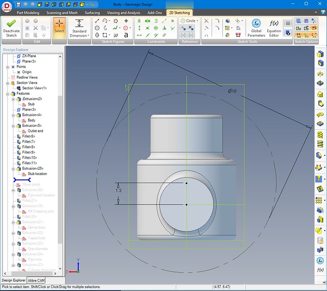 Finding the smallest stock Finding the smallest stock by Roger Froud, on Flickr In this view, the rotary table is on the right with the axis of rotation horizontal ie lined up with the green X arrow on the triad. You'll notice that the W dimension is the front to back dimension ie in the Y-axis and it's 10mm since the diameter of the stock is 10mm The H is half that because we're only defining stock for the top half of the 10mm bar, we can only reach half way down before turning it over. Y0 value is the corner offset which is 5mm less the 1.2mm we worked out just now. It's negative to move the corner away from the zero. The others are more obvious, the L dimension of 9mm is the length of the stock for the part in the X-axis, so that has to be offset by -9mm to put it beyond the end of the work which is just under 8.5mm long. I always make sure there's at least 0.5mm to clean up on the end. Anyway, the model can be turned round to make sure that it looks like it's in the middle of the stock and nothing is poking out anywhere. So far so good, next we're going to see what happens when we define a too path 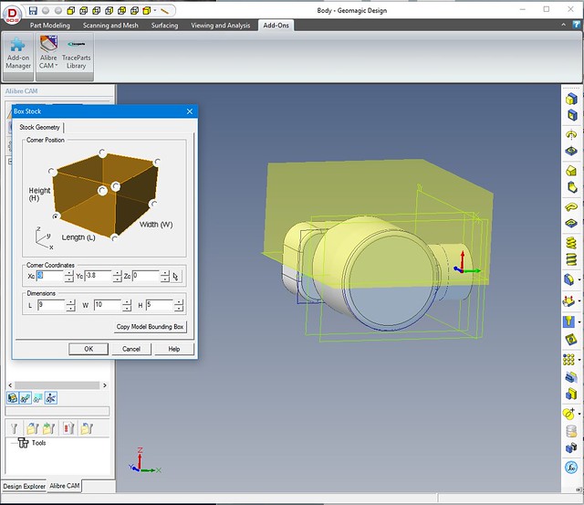 Stock definition Stock definition by Roger Froud, on Flickr |
|
johnthepump
Part of the e-furniture
 Building 7 1/4"G Edward Thomas
Posts: 493 
|
Post by johnthepump on Mar 21, 2016 22:08:22 GMT
I think at my age, I'll stick to getting my head around 2 1/2D. I have been greatly encouraged by your work and spend more time on CAD.
John.
|
|
|
|
Post by Roger on Mar 21, 2016 22:31:15 GMT
First a definition of Horizontal Roughing. This is where we're asking the software to remove all of the stock, leaving the model intact within it. This is the Horizontal Roughing dialog box, and you can see all those tabs that you can use to get the output you want. We won't look at them all, most of the time you don't need them. First up is the Cut Parameters tab.... The Intol and Outol values are how close you want to path to hug the model geometry. You can set these to 1 micron if you want, but there's no point when you're leaving 0.3mm stock, it will take ages to calculate the toolpath. I've chosen 50microns, about 2 thou, that's plenty close enough. I usually set the Stepover control to 50% which seems to give satisfactory results most of the time. If you make it bigger, you'll find that parts get left uncut. 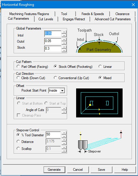 HR Cut parameters HR Cut parameters by Roger Froud, on Flickr This is the tab to control how quickly you progress with the vertical cut levels. I usually define the distance. In this case I'm using a 5mm ripper which is capable of cutting much more, but I can go mad as it will end up with very little material supporting the part when we reach the end of the second side. there are no flat portions so we don't need to tell it to clean those up. 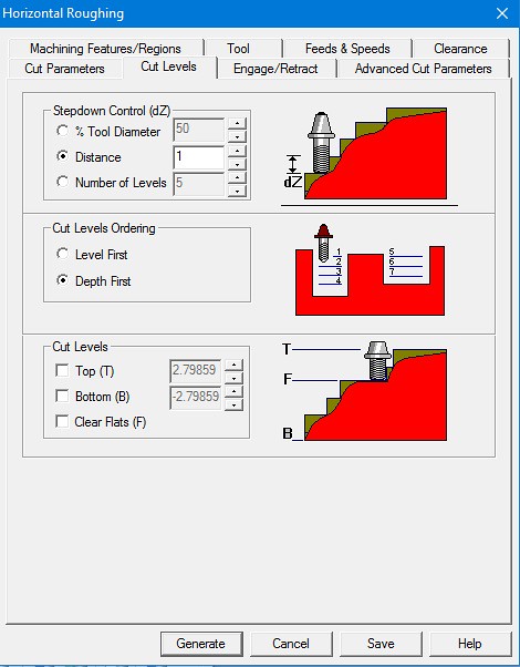 HR Cut levels HR Cut levels by Roger Froud, on Flickr Because I've set the cuts to 1mm, I've got to make sure that the rapid approach is to more than that else it's going to crash. You'd think there would be some software to detect this simple situation, but there isn't! So here I've set the height to 1.2mm and the angle to 5 degrees. The default is 10degrees and I find that's too aggressive on most metals. 5 degrees seems to work with everything so I use that everywhere. 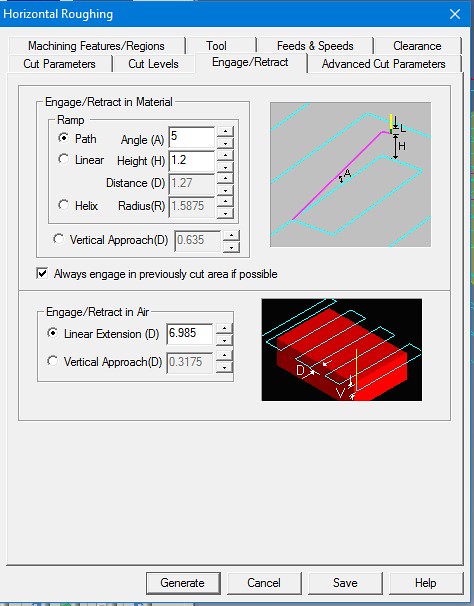 HR Engage retract HR Engage retract by Roger Froud, on Flickr Here you can see the different elements of the cuts and how you can define the feedrate at each of them. There's little point it making them different except for that initial plunge. I tend to be a bit cautious on that Pf value, just in case I've messed up and it hits the work at that speed. It's still not going to like it, but it's better that going in like an express train. 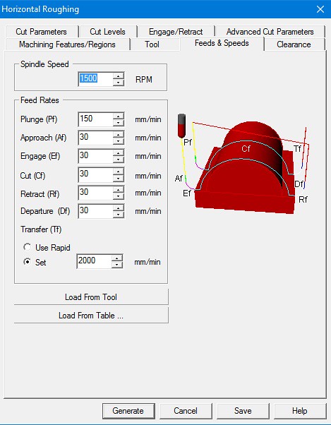 HR Feeds speeds HR Feeds speeds by Roger Froud, on Flickr Once all these things have been set, you click Generate and this is what you get.... At first glance this looks ok, but look where the triad is, and imagine that you've got a piece of 10mm bar carrying on to the right, leading to the chuck on the rotary table. The tool is wrapping partly round the end, and that's no good. If I'd defined the stock to be even further to the right it would have gone right around the end. Defining the stock for just the top half has contained the tool path to the top half of the model which is good. If we'd defined it to enclose the whole part, it would by default have tried to remove all of that. If you look back to the Cut Levels tab, you can see that there's a Bottom value that we could have set to zero to achieve the same effect. That would had clipped the output to the centre line. There's usually more than one way to do any of these jobs. 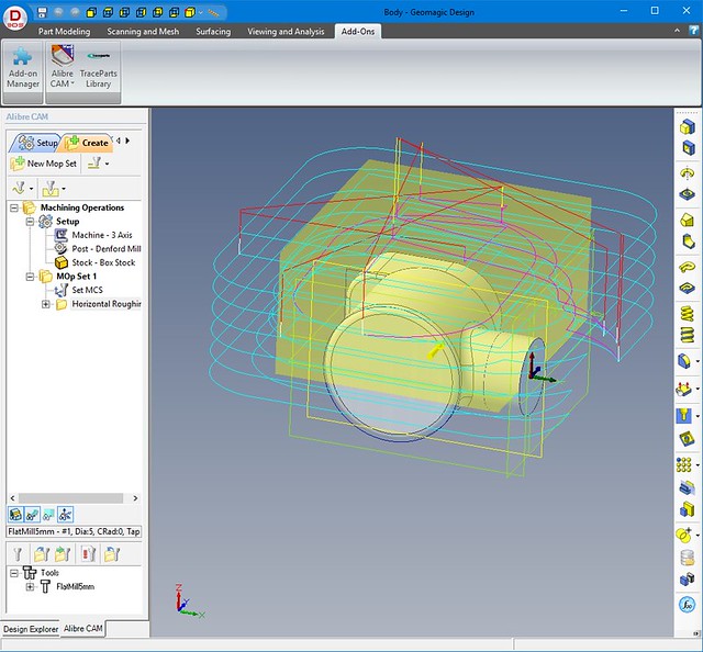 HR first attempt HR first attempt by Roger Froud, on Flickr So next we'll see what we can do to prevent the output from straying where we don't want it to go. |
|
|
|
Post by Roger on Mar 21, 2016 22:35:32 GMT
I think at my age, I'll stick to getting my head around 2 1/2D. I have been greatly encouraged by your work and spend more time on CAD. John. Hi John, I'm sorry, 'at my age' doesn't wash with me. By all means do the 2-1/2D until you're happy with it, then you'll be surprised at how this isn't such a big step. It all looks much more scary than it is. The software is clever so that I don't have to be! It's not trivial, but equally well, it's not half as bad it might appear. It's good to step out of your comfort zone sometimes. |
|
|
|
Post by Roger on Mar 21, 2016 23:12:05 GMT
In this view, we're looking down on top of the machine table, with the rotary table to the right. The blue line is a new sketch I've called 'Containment' which is flush with the RH end of the model, but 6mm clear everywhere else. That means that the 5mm cutter can reach everywhere, including the extra little bit of stock we're leaving, except at the RH end. The cutter needs to be confined to this box. 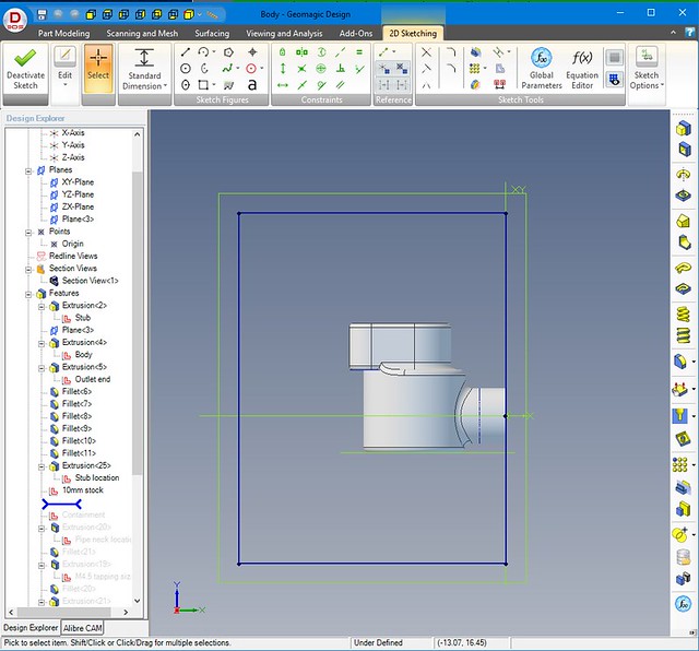 Containment Containment by Roger Froud, on Flickr Here's the Horizontal Roughing dialog opened up again, and I've clicked the 'Select Containment Regions' button, then gone to the Design Explorer and selected that 'Containment' sketch from the list. 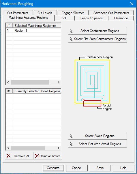 HR machining regions HR machining regions by Roger Froud, on Flickr Clicking Generate now gives us the following output which only wraps round the main features, not the end. Compare this with the one in the earlier post. 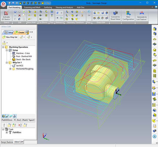 HR contained area HR contained area by Roger Froud, on Flickr So you can now see the blue centre lines of the tool as it works its way round the job, and the other colours where it's entering and exiting the work. So long as we've set up the approach to be greater than the depth of cut, this ought to just work. Now we're ready to create some G-code and get the machine ready for roughing this out. |
|
|
|
Post by runner42 on Mar 22, 2016 5:59:54 GMT
Hi Roger,
I tried desperately to follow your explanation but I soon became lost. You appear to be putting a lot of effort into this topic, you did say that it would be of limited interest, what is your target audience?
Brian
PS On second reading things became clearer due mainly to the fact that I needed greater magnification to identify the headings in the design explorer that you referenced in the narrative. I have reached a conclusion rightly or wrongly that this approach has high material wastage. Whereas I with my limited skills and no milling machine would attempt to fabricate the same thing using discreet parts and silver solder them together you adopt a similar approach as the sculptors using your skills to produce the part from a solid block of metal.
|
|
|
|
Post by Roger on Mar 22, 2016 8:04:50 GMT
Hi Brian,
I estimate the number of people interested in this as being between about three from the point of view of actually using it, and perhaps ten who are curious to know what it's all about. That's about it.
My purpose of showing this is twofold. Firstly, one or two people might be encouraged to make more of the CNC equipment they already have. Secondly, it seems wrong to conjure parts from the screen into metal without giving some sense of what processes are involved.
Hopefully it also answers those who think you can point a camera at something and then ask a machine to make if for them.
The material wastage aspect is one of choice. There's nothing to stop you getting material that's close to the size you need and carving the part from that. The problem with that approach is that you end up having to source many short lengths of different sizes, whereas I buy lengths of a range of bar sizes and make everything from that. In most cases it really doesn't cost significantly more, and I've almost always got something in stock. If the CAM software would allow a better definition of stock, it would be less wasteful.
Bear in mind that this part is coming out of 10mm diameter stock. In a case like this, the wastage isn't important, although on the screen it looks appalling. Fabricating or casting is always going to use less material.
Your comparison of this with sculpting is a good one, and the process is done pretty much the same way. Hacking off the bulk of the material you don't want is the first step, then getting ever closer to the desired shape follows in as few steps as you can reasonably take to get the dimensions and finish you require.
With regard to putting a lot of effort into the topic, I have to go through these processes to make the parts, so taking a few screenshots along the way isn't too time consuming. Hopefully it will be of some interest, even if that's just academic.
|
|
|
|
Post by KennLindeman on Mar 22, 2016 8:14:24 GMT
Hi Roger
Been following your speedy build for some time now even though I am not building a speedy. And although a cnc is still only on my bucket list I am following this with keen interest. Thanks for all the effort you are putting in to keep us up to date with what you are up to
Regards
ken
|
|
|
|
Post by Roger on Mar 22, 2016 18:40:34 GMT
Let's take a quick look at how this Horizontal Roughing tool path is converted into usable G-Code. In the case of my software, all you have to do is point to the Horizontal Roughing machining operation we've created and then use the Right Mouse button to get a context menu. One of the options is Post, and this is what you get when you click that. You can see that it's very long, but also very simple. A Post Processor takes the output from the CAM software and adds whatever commands your particular control needs. I've modified one of the supplied Post Processor scripts so that it always outputs X,Y and Z and converts all arcs to straight lines. The result is more verbose, but it's dead easy to follow and restart from anywhere in the program. So from the top, the first line is just a comment, anything in brackets is ignored by the controller. The second line gives the tool number which isn't used in this application. I do use it when creating output for using the Mill as a Lathe, so it's left in. The S1500 sets the spindle RPM and the M03 turns it on. The G01 command tells the control to move from where it is, to the ordinates that follow, all at the same time in three dimensions. Clearly this is not something you can do by hand. The F2000 is the default high speed move as 2000mm/min, the F30 is 30mm/min for the actual cutting. It really doesn't get any more complicated than that. This is my little utility program that I wrote to transform the data for some more complex situations. Most of the time I close this and it saves the file with a .nc extension so the control can use it. The CAM program has been told to output a .cnc file which I intercept with this program. This means that I have two G-code files for every path I create. Most of the time they contain the same information. 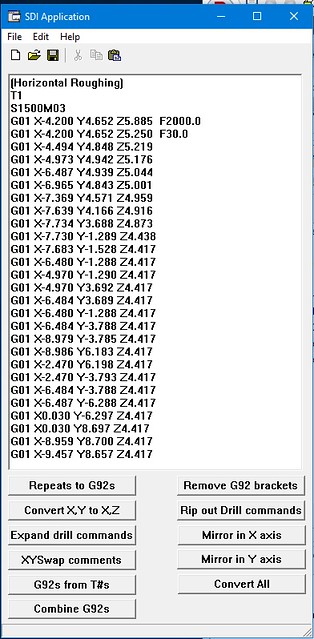 Horizontal roughing G-code Horizontal roughing G-code by Roger Froud, on Flickr If you remember, we're going to machine this from both sides, so that means the G-Code needs to be a mirror image in the Y-axis. I've recently added this function to the Utility program for convenience, and this is what you get when you click the 'Mirror in Y-axis' button. As you can see, it's just changed the sign of all the Y-ordinates, and added a comment on the head of the file to say it's been done. I give these files sensible names and save them in the job folder. I expect you can already see that 3D modelling creates a lot of files, and the potential for getting in a mess is huge. I create folders for every part, however trivial. That way any tool paths or notes files can be kept together. 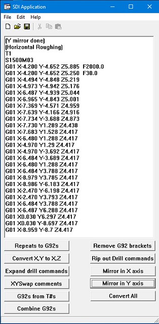 Mirrored G-code Mirrored G-code by Roger Froud, on Flickr |
|
|
|
Post by Roger on Mar 22, 2016 18:44:06 GMT
At the moment the machine is tied up, so I can't show the rouging at this point. So let's move on to the next step. First a definition. Horizontal Finishing is not interested in the stock, it's assumed that you've roughed all that away. This operation tries to hug the model surface in horizontal slices. If you recall, we used a 5mm ripper in 1mm horizontal slices to remove all except 0.3mm of the material, but that leaves some pretty jagged edges. This is where the judgement comes into play. Do you leave huge steps in roughing that then take a lot of cleaning up, or do you takes ages with many fine slices. There's no easy answer to this, it's a compromise. So this is what we see when we select a Horizontal Finishing operation. Most of this is the same as on the Roughing, but there are different options on some of the tabs. Here's I'm setting the horizontal slices to 0.25mm, half of the roughing cut depth, 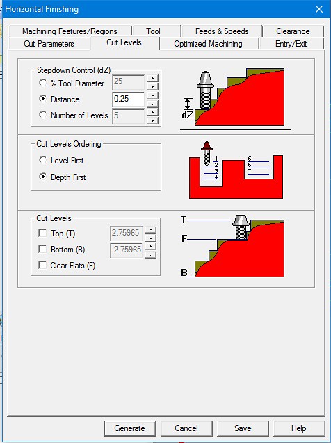 HF cut levels HF cut levels by Roger Froud, on Flickr There's 0.3mm still to come off, but it's pretty jagged in places. There's also a problem in that the 5mm cutter is much too big to get into the corners of the finished part, so there's more material to remove from those places. This prevents us from using a very small cutter at this stage because we'd have to use a very small vertical slice indeed to prevent the cutter from being broken when it reached those corners. Again, this is a compromise, we're trying to get quickly to the finished model surface, so I've selected a 2.5mm 2-flute cutter which can get much tighter into the corners than the 5mm one, but is man enough to get on with the job and cut through the jagged edges without breaking. Here I'm still leaving 0.1mm above the surface and not hugging it closer than 10 microns because there's no point at this stage. I've not shown the tool selection, but you can choose the shape of the cutter and fill in the diameter. There are a lot of things you can set to define the length of the flute and even the tool holder, but I keep it simple and just set the diameter for the type of tool I'm using. In this case the tool has a flat bottom, and the software accounts for that. 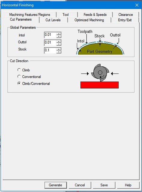 HF cut parameters HF cut parameters by Roger Froud, on Flickr I've set 0.25mm horizontal slices, so the 3D entry has to be more than that. Again I've used my 5 degree approach slope. You'll notice that you can also select to come in from the side, clear of the work of you want. I generally used the slope along the tool path for convenience since it only takes two parameters to set it up. 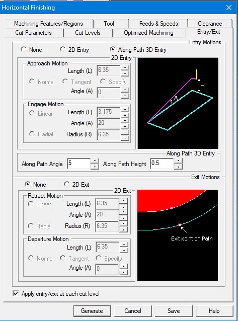 HF entry and exit HF entry and exit by Roger Froud, on Flickr Clicking Generate gives the following output. It's remembered that I've defined a Containment region to avoid the end so I didn't need to tell it that again. Sometimes you need different ones, but this time it's ok. There is a problem though. You can see that the tool path is trying to hug the profile silhouette, right down to the base, and we don't want it to do that. You can now see that there are two machining operations in the Alibre CAM pane called Horizontal Roughing and Horizontal Finishing. 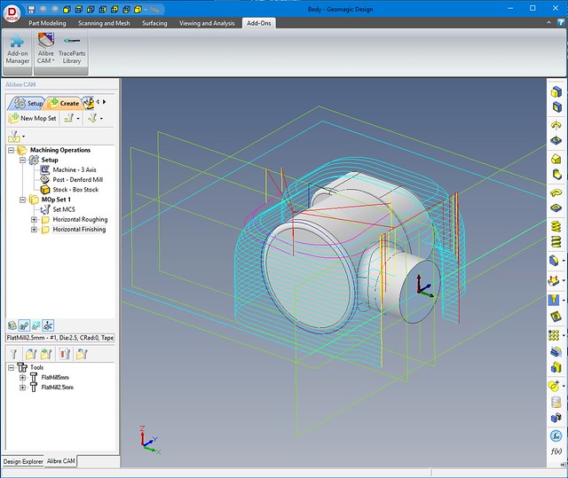 Horizontal finishing Horizontal finishing by Roger Froud, on Flickr |
|
|
|
Post by Roger on Mar 22, 2016 19:03:36 GMT
So the Horizontal Finishing is almost ok, but the cuts are going below the centre line of the part, right to the bottom. Opening up the Horizontal Finishing operation dialog again, we can select the 'Bottom (B)' check box, and enter zero if we want the cuts to stop there. That's because we've set the Machine Coordinate triad to be zero in the Z-axis at the centre of the model. I've chosen to go slightly below the centre line because there's a tendency to leave a wafer at that point. We'll end up with a witness there anyway when we've finished. 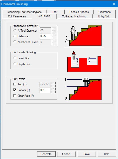 HF cut levels cropped HF cut levels cropped by Roger Froud, on Flickr Clicking 'Generate' gives us the following which is now ready for outputting. 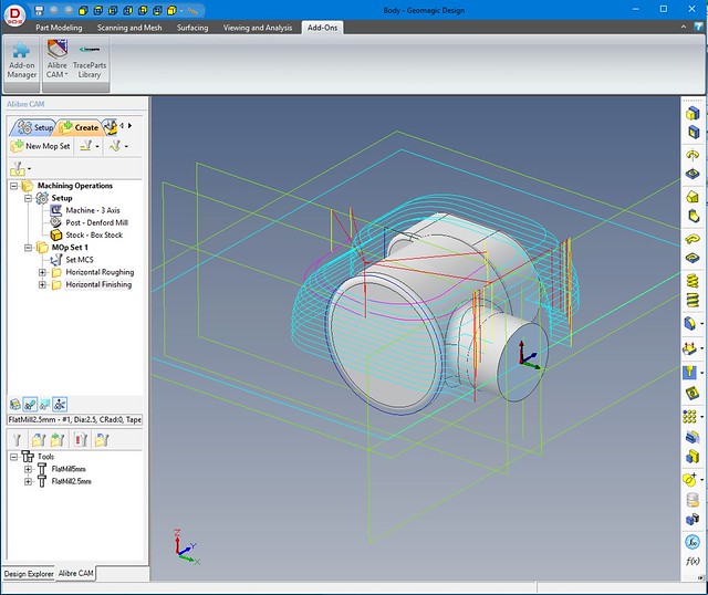 Horizontal finishing cropped Horizontal finishing cropped
by Roger Froud, on Flickr And this is how the output looks. Pretty boring and much the same as the previous one. 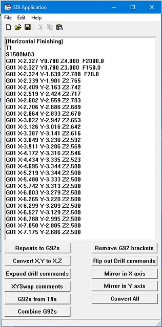 Horizontal finishing G-code Horizontal finishing G-code by Roger Froud, on Flickr |
|
|
|
Post by jon38r80 on Mar 22, 2016 20:02:22 GMT
Like Ken and Brian, I find this interesting as I have been considering how to adapt the Warco mill I have to cnc control mainly for no other reason than I enjoy the mental challenge. Looking at your build thread and the adaption of the sieg in the tools section is an inspiration. There are lots of places where you can see the grubby metal adaption but very little about using the software that makes sense to me. If you can keep up the effort it is much appreciated.
|
|
|
|
Post by Roger on Mar 22, 2016 20:12:16 GMT
To finish the part, we're going to need to trace the profile closely with at least two passes with smaller cutters. Definition... Parallel Finishing. This is where the slices are Vertical instead of Horizontal. The tool may continuously follow the contours without a break, but often it starts and stops after each slice. Selecting the Parallel Finishing machining operations opens this dialog box with the familiar tabs. Here you can see that I've got even closer to the final model by leaving just 0.05mm (2 thou) stock, and tracking to within 1 micron. The stepover control decides the slice width. Obviously it takes a lot longer if the step over is small. I'm using a 1.5mm end mill for this so we're finally getting quite tightly into the corners. Again it's a compromise between cutter diameter and strength, and being able to get into the corners. Going too quickly to the smallest diameter cutters is going to end up breaking them in the corners, so we need to do this first. You can see that you can change the angle of the slices. This is handy to force the path to follow the curves rather than go along them. The Top and Bottom selection decides which end of the model the cuts start from. 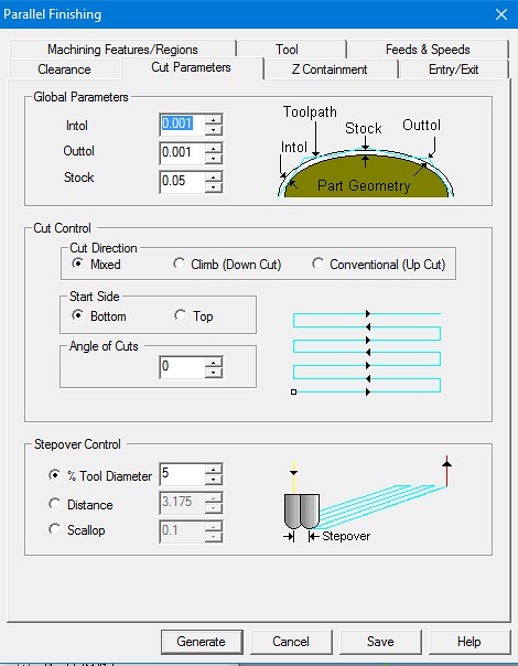 PF cut parameters PF cut parameters by Roger Froud, on Flickr The entry needs to be gentle and from the side rather than diving straight down, so I've chosen to go for a 45degree approach starting 1mm away from the edge after the rapid plunge. 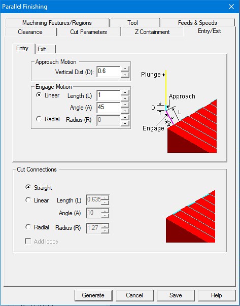 PF entry and exit PF entry and exit by Roger Froud, on Flickr And this is the result. The finishing cuts are just with a small diameter ball mill and even finer step over with zero stock. Other than that, it's the same Parallel Finishing so I won't repeat myself. You can now see that there are three machining operations in the Alibre CAM window. If there are several operations using the same tool size, you can create a new Folder for them and group them all together in the Alibre CAM window. That way you can select all of the operations together and output them all as one piece of G-code so they can be run one after the other without stopping. 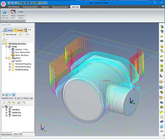 Parallel finishing Parallel finishing by Roger Froud, on Flickr Ok, that's a whistlestop tour of 3D machining, but all the essentials are there. Of course there are many bells and whistles and tabs we haven't even looked at, some are self explanatory, others not. I have no idea what many of the control parameters are, but I seem to get along ok with the ones I've shown. I'll show the practical side of taking the G-Code to the machine and a bit more about the setting up, but that's really all you would need to know to get started. Pretty much all the 3D machining I've shown on the 'Speedy' thread has been done this way, and it doesn't take long for it all to look very familiar. It's not that difficult, but you need to look closely at the tool paths to see if they really do what you want. You also have to nurture a good understanding of what you can get away with in terms of cutter size, feeds and speeds. I'm sure everyone settles on their own pet sequence of cutter sizes and depths of cut at each stage so as to get the job done in an acceptable length of time. There's an information tool that gives an estimate of the time each operation takes. It's not that accurate, but if it say 5 hours, you need to think again because it's going to take a long time! |
|
|
|
Post by Roger on Mar 22, 2016 20:21:09 GMT
Like Ken and Brian, I find this interesting as I have been considering how to adapt the Warco mill I have to cnc control mainly for no other reason than I enjoy the mental challenge. Looking at your build thread and the adaption of the sieg in the tools section is an inspiration. There are lots of places where you can see the grubby metal adaption but very little about using the software that makes sense to me. If you can keep up the effort it is much appreciated. Hi Jon, I'm pleased you find it interesting, I know it's not to everyone's liking. You have a nice spread of machine conversions featured here. Both Doug's Sieg and Ed's conversions show the different machines and ways of going about it. None of our machines are ideal, but they are all made enormously more capable by virtue of the conversions. The more you can afford to spend on the software, the easier it gets, but it's certainly not cheap. Fortunately I don't have to justify the expense, as my machine is sometimes used for commercial purposes. Conversions are pretty easy to do, as long as you're happy to dabble with electrics. Most of the Electronics works straight out of the box. I look forward to you starting a thread charting your journey to convert your mill. |
|
|
|
Post by Staffordshirechina on Mar 23, 2016 8:29:52 GMT
Roger,
I too find your posts interesting.
Starting with a homemade CNC of Axminster XY table variety and after the success of that I bought a Bridgeport Interact. I use CNC where I can in preference to marking out etc.
I have yet to machine anything that is true 3 axis. I suspect most of us find that our needs are more straightforward.
I am currently building a 6" scale Burrell Road Locomotive to Edward George's design and the CNC makes short work of lots of the mundane tasks.
My software route at present is AutoCAD to Cambam to mach3 for the homemade and AutoCAD to Cambam post processed to Heidenhain for the Bridgeport.
Eventually something will come up that needs 3d work!
Les
|
|
|
|
Post by Roger on Mar 23, 2016 8:58:15 GMT
Hi Les,
It's good to hear from you. I wish I had room for a Bridgeport, but sadly my space is too limited. The little Denford is the next best thing, but occasionally it could use to have a bit more table travel and for it to be a little more rigid. I know the Heidenhain TNC150 and 151 because they're on old PCB routing equipment that I still support, and I do the odd repair on them if I have to. They're getting hard to support now though, Heidenhain like to remove support, presumably to force people to upgrade. Usually it just ends up in the machine getting scrapped though.
I think it was over two years before I found a job that could only realistically be tackled with 3D, most of what I do is 2-1/2D. I avoid it wherever possible because it takes too long. I never design things that need it, but in the case of 1501, the design is often in the form of a casting and there's no way round it if you want it to look right.
3D is one of those things that has a steep learning curve to get started, but there's nothing particularly difficult. Setting the tools takes a bit of getting used to, and I'll cover the way I do that in this thread shortly. When you've used it a few times, you'll find that some things are better done that way. Fluting on connecting rods is one such case that can be done manually, but is easier to do using 3D machining.
I don't know AutoCAD as it is now, it used to be awful and unintuitive. I'm sure it's better now. I presume that's a 2D package? If it is, you won't have any difficulty making the transition to 3D, it's pretty easy. I think people are intimidated by it because of the amazing results you can show on the screen. What they don't realise is that it's the software that's really clever, you don't have to be clever to use it.
|
|
|
|
Post by Roger on Mar 25, 2016 22:43:16 GMT
So this is how I've chosen to set up this particular job. I've first clocked the bar to get it central even though I know I've got to offset it in the jaws. Then I've moved it over simply by turning the relevant jaw screws by 1/4 turn and then checked it's about right with the height gauge. So long as it's not miles out then it's fine. 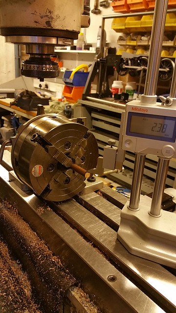 20160325_164938 20160325_164938 by Roger Froud, on Flickr This is how I find the centre of rotation of the job, which must coincide with the rotary table centre. I use the wobbler on one side, click zero on the Y-axis DRO then... 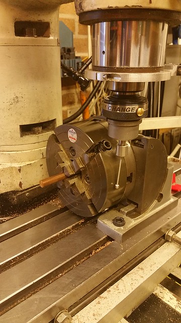 20160325_165307 20160325_165307 by Roger Froud, on Flickr ... move to the other side at the same height. I use a combination of the MPG (Hand control Manual Pulse Generator) and typed commands, being very careful what I tell it to do! Once the wobbler has found the other side, I halve what's on the Y-axis DRO and type that in as the current position. NB:- I ALWAYS lock the quill when setting up things like this else it won't be right when you finally do lock it. I've put a scribed line on the locking handle and one on the machine so that it's always tightened to the same amount. 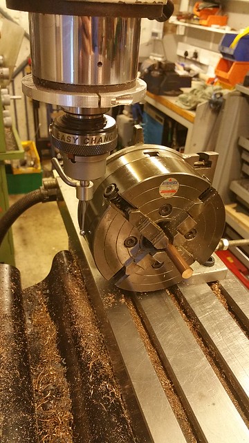 20160325_165622 20160325_165622 by Roger Froud, on Flickr The X-axis is now set, the end is found by the wobbler, the DRO set to -3.5 (it's a 7mm ball) and then I command the X-axis to go to the opposite end of the job using the drawing to see how far that is. I go another 0.2mm to make sure the end clears up and then click zero on the X-DRO 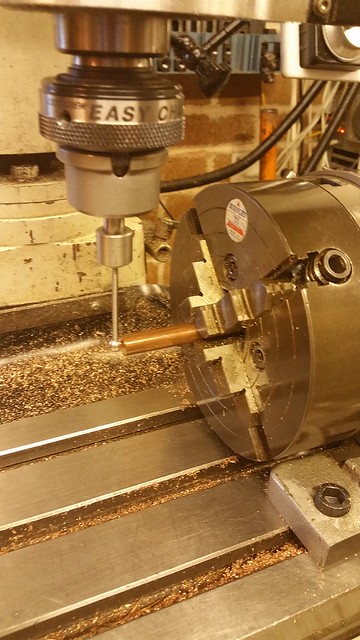 20160325_165841 20160325_165841 by Roger Froud, on Flickr Now the cutter is fitted, in this case a 5mm ripper, and I move over to the top of the 4-jaw, moving the Y-axis to zero. The Z-axis DRO has been set to 76.04mm which is the radius of my 4-jaw chuck. 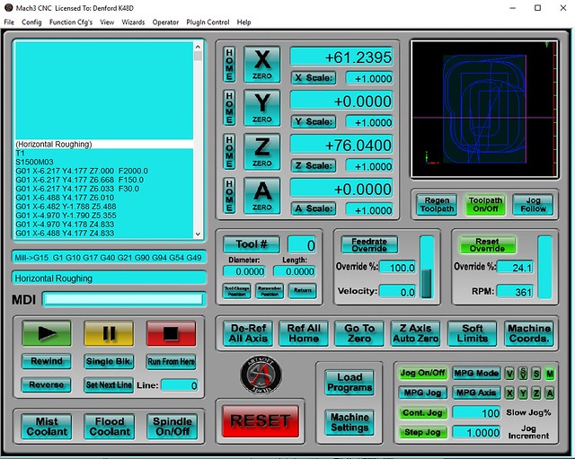 Z-height setup Z-height setup by Roger Froud, on Flickr The cutter is then lowered gently onto the top of the chuck and locked into position. Then it's commanded to Z+80 to clear the chuck. 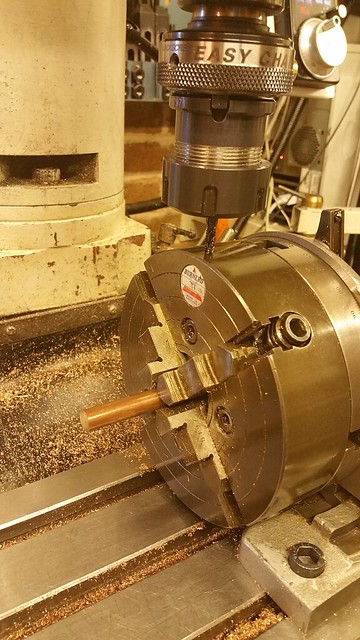 20160325_170347 20160325_170347 by Roger Froud, on Flickr This is the first 'sanity check', moving the cutter to the side and lowering it slowly to Z0 to make sure it's on the centre line. 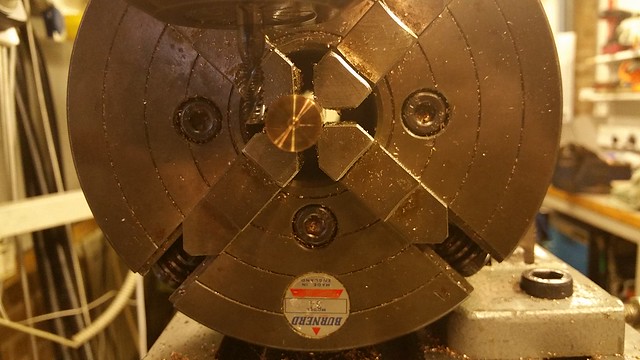 20160325_173451 20160325_173451 by Roger Froud, on Flickr Looking through the first few lines of the program, it lowers down to Z4.833 and stays there, so that's the first cut height. 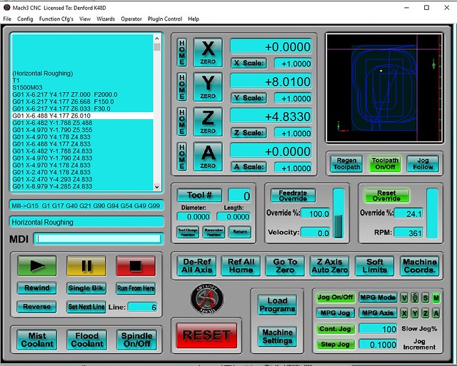 Sanity check Sanity check by Roger Froud, on Flickr moving to Z4.833, this is the second 'sanity check' to make sure it's going to take a sensible cut, 1mm in this case. Sanity check by Roger Froud, on Flickr 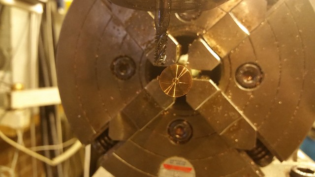 20160325_173538 20160325_173538 by Roger Froud, on Flickr Then it's just a matter of moving the cutter clear of the work, overriding the feed to the slowest possible and then single stepping from the start to make sure it all looks plausible. I always look at the position of the cutter on the DRO and see what the next move is going to be for those first few moves. If I can't see that it makes sense at any point in the setup, I stop and go back. In this case I'd somehow entered the wrong Z height to set the tool, and it was about 2mm too low. You really don't want to just dive in and run something if that sort of error has been made. Fortunately, my sanity checks spotted that one and I reset the tool to the correct height. These errors are easy to make, so it's vital to really look long and hard at what it's about to do before you run it. So this is how that all looks in practice. As you can see, on such a small part, 1mm cuts is pretty grainy but it does get the job done quicker. 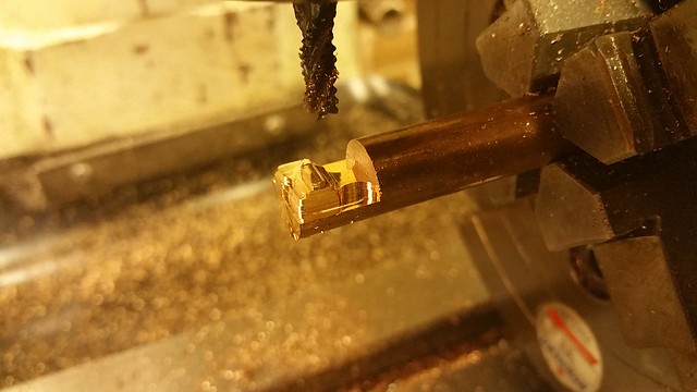 20160325_182121 20160325_182121 by Roger Froud, on Flickr This is after the Horizontal Finishing pass with the 2.5mm 2-flute 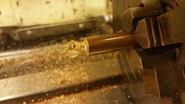 20160325_193730 20160325_193730 by Roger Froud, on Flickr and a remarkably good finish after the 1.5mm Parallel Finishing pass. 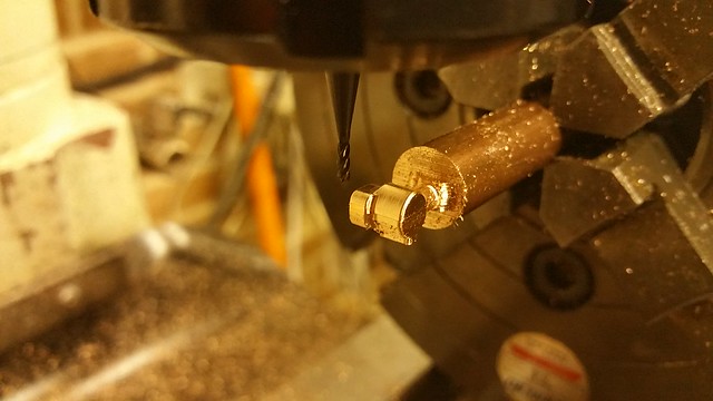 20160325_201853 20160325_201853 by Roger Froud, on Flickr At this point, I've taken a look at the drawing and noticed that I've managed to exclude the boss on the end when I was excluding the holes... Doh! I could probably Silver Solder that bit on, but to be honest it's not worth the trouble. I've changed the machine zero triad to allow the work to be set up centrally, and on the end so that will speed things up since there are six required altogether. It's a good example of the sort of thing that goes wrong from time to time, and I use these events as an opportunity to go back a few steps and tweak feeds, speeds and the amount each pass cuts in the light of seeing how it machined. I wouldn't bother messing about with it for just one part, but it's worth it for six pieces. It's a never ending learning experience, but that just makes it more interesting. |
|
johnthepump
Part of the e-furniture
Building 7 1/4"G Edward Thomas
Posts: 493
|
Post by johnthepump on Mar 26, 2016 8:45:09 GMT
Hi Roger,
This is very interesting, one question is your 4 jaw chuck on a fixture or is it 4th axis?
Regards John.
Ah. looking further back in the thread I've seen the answer to my question.
When I zero the Z on my machine I use a piece of 0.1mm brass shim and use the Z set gauge that is another page of Mach 3. As going between pages was a bit of a trial. Wilf found away of fitting all I needed onto the main screen and it does make things so much easier.
John
|
|
|
|
Post by Roger on Oct 29, 2016 17:57:44 GMT
I won't post this on my main thread as it's not of general interest. This is the base of the chimney, minus its copper top. The inside is tapered at the top and has a parallel hole through the rest of it that engages with the petticoat pipe. There are two pockets for cap heads and also 8 tiny holes for cosmetic screws. Now this could all be done with 3D machining, but it would take way too long, and the parallel outside portions wouldn't be super accurate. 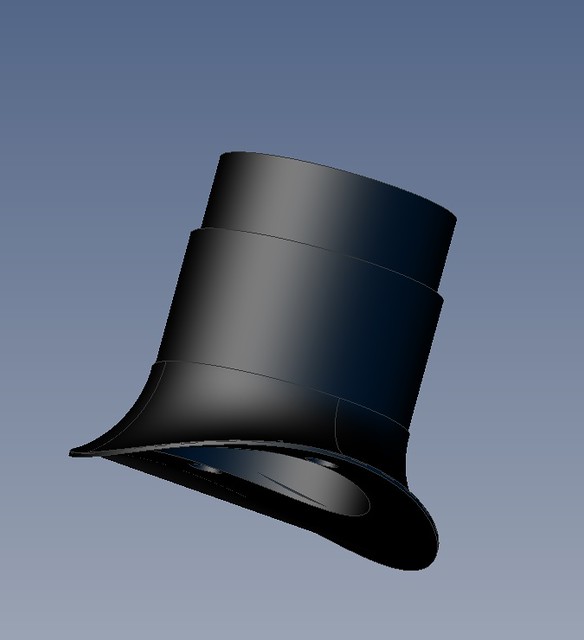 Chimney base Chimney base by Roger Froud, on Flickr What I've elected to do is to turn as much as possible, and only 3D machine those things that can't reaslistically be done any other way. So here's a model that has had the internal features suppressed and a sleeve added to the smaller diameter so that can be finish turned and blended with the 3D part later. Again, the smaller diameter could be 3D machined, but it's much quicker to rough that out and restric the 3D area to the flange. 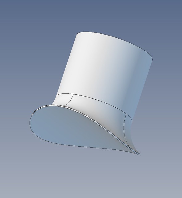 Simplified chimney base Simplified chimney base by Roger Froud,on Flickr So this is the simplified shape..... 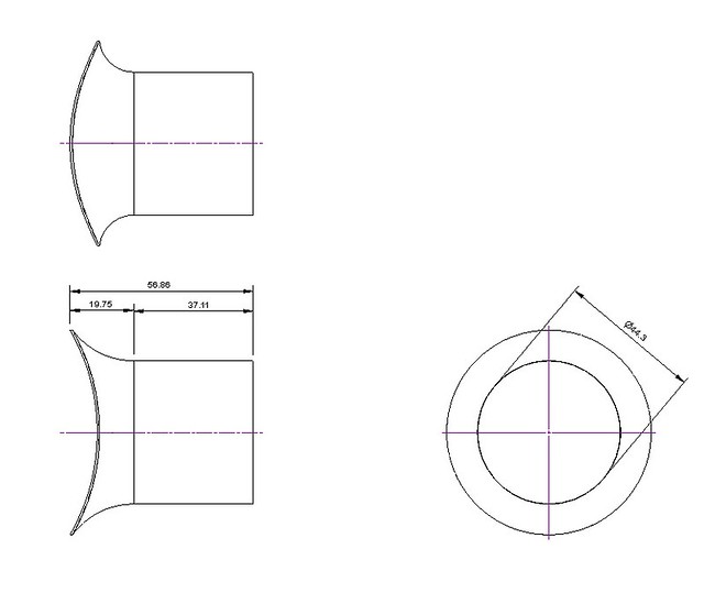 Simplified chmney drawing Simplified chmney drawing by Roger Froud, on Flickr ... and this is the stock it's going to be made from. There's a 30mm length that's turned accurately to the rest of the stock so that it can be used as a machining reference when it's transfered to the lathe later. 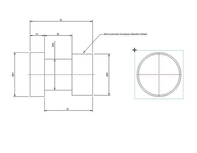 Stock drawing Stock drawing by Roger Froud, on Flickr This is the plan view of how it will be on the mill, showing the containment region. I've excluded the smokebox curve for two reasongs... Firstly, I can't support the end with a centre if I machine that at the start. Without support, it's going to take two or three times as long because I can't take a big cut. Secondly, The shape is a simple one that will take less machining time if it's defined as a simple arc. That will have to be done slowly because the centre will have to be removed for that. 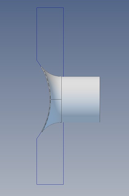 Containment region Containment region by Roger Froud, on Flickr This is how the crucial horizontal roughing pass looks with a 16mm ripper and 2mm deep cuts which ought to take about an hour and a half. I've restricted the Z level to -0.5mm so that there's a little overlap when I turn it over. If you don't do this, there will be a significant witness at the centre line. Unfortunately you can't define circular stock, so it's trying to remove what it thinks is there. I've defined the rectangular stock to be 0.5mm bigger than the part to make sure the cuts go right round the outside. 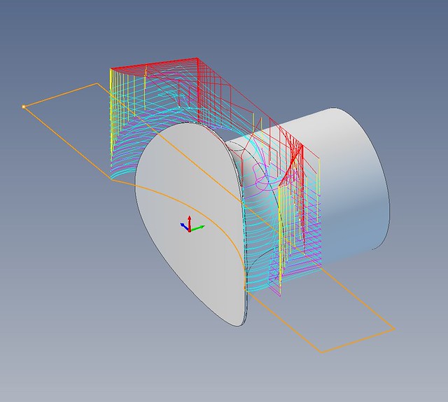 Parallel roughing Parallel roughing by Roger Froud, on Flickr This is a very rough parallel pass using the same cutter, leaving 0.3mm of stock. 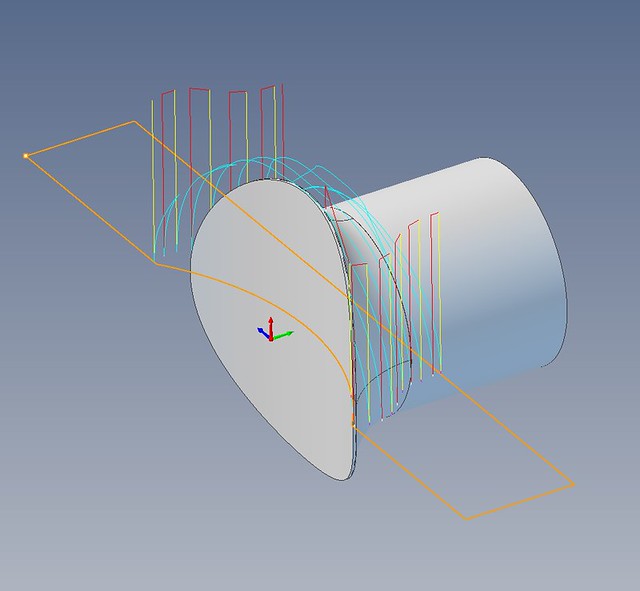 Parallel rough finishing Parallel rough finishing by Roger Froud, on Flickr .... and this is a finer pre-finish cut with a 16mm 4-flute so that it leaves just 0.1mm to clean up. If you don't do this, it will leave marks from the initial roughing when the fine finishing pass is done. It also restricts the speed that you can go at. 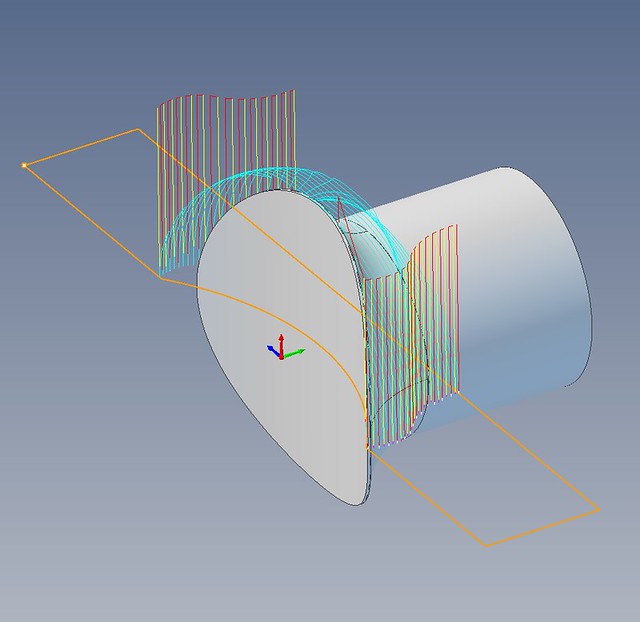 Parallel pre-finishing Parallel pre-finishing by Roger Froud, on Flickr ... and finally, this pass is in 0.1mm increments to get a really good finish. This would take a very long time if you had to go slowly, but the previous stage allows the speed to be really ramped up. 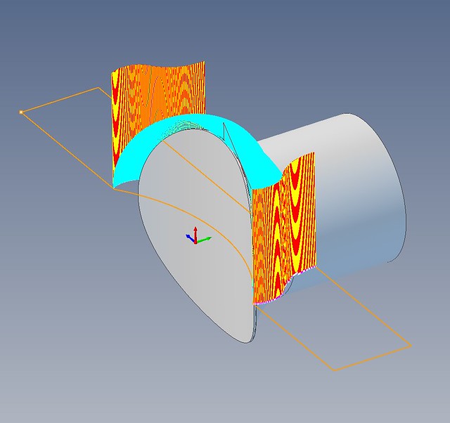 Parallel fine finishing Parallel fine finishing by Roger Froud, on Flickr |
|


