|
|
Post by Roger on Feb 4, 2022 18:59:02 GMT
Hi John, That explains a lot. Here's a page that shows the various arrangements, and I'd expect the bearings to be in the directions shown in figure 4m ie so that an load on the shaft loads up the bearing next to the end you're pressing from. I suppose it's possible that the bearings might have been fitted the wrong way round. If not, you can either shim the centre spacer to give a couple of tenths preload, or make a new spacer that's longer. You really don't need much preload because the bearings are really stiff. It does appear that quite a few spindles have the Deep groove bearing just floating without any preload. Personally, I think that's horrible, and is likely to make it less stable. A light preload with a wavy washer is a better option in my opinion. Hi Roger, The link hasn't worked for me, I have now stripped the head down again and tried running them in the lathe with preload and they are all very noisy. So I'm going to replace them, the good news is that I moved the machine out to access the noisy motor I noticed it had grease nipples so a shot of grease in each and the motor runs quietly. John. Hi John, That's strange, the link works here. Maybe it's because it needs a pdf viewer. It sounds like they've been damaged, possibly by running without preload. Such is life, hopefully the bearings won't be too expensive. I'm not sure what grade they need to be. We used to fit ABEC7 for all of the spindles we rebuilt. |
|
johnthepump
Part of the e-furniture
 Building 7 1/4"G Edward Thomas
Posts: 493 
|
Post by johnthepump on Feb 4, 2022 19:09:23 GMT
All interesting stuff John - a lot of variations. I spoke to a Castrol Technical Rep about which grease to use instead of the obsolete Spheerol AP1 and he told me to use Spheerol EPL 1 instead. Reg Hi Reg, Thanks for that info on grease. When I bought the machine I bought some Rocol Sapphire 1 which is listed as NLPGI 1 Type, Which at the time seemed to be suitable, back in the day most of my spares came from RS Components as I needed things next day. I have now stripped the head down again and the photo below show the layout of the components as taken apart.  02.2.22 02.2.22 by John The Pump, on Flickr John. |
|
johnthepump
Part of the e-furniture
Building 7 1/4"G Edward Thomas
Posts: 493
|
Post by johnthepump on Feb 4, 2022 19:23:44 GMT
Hi Roger, The link hasn't worked for me, I have now stripped the head down again and tried running them in the lathe with preload and they are all very noisy. So I'm going to replace them, the good news is that I moved the machine out to access the noisy motor I noticed it had grease nipples so a shot of grease in each and the motor runs quietly. John. Hi John, That's strange, the link works here. Maybe it's because it needs a pdf viewer. It sounds like they've been damaged, possibly by running without preload. Such is life, hopefully the bearings won't be too expensive. I'm not sure what grade they need to be. We used to fit ABEC7 for all of the spindles we rebuilt. Hi Roger, I just tried using my iPad and it opens OK thanks. I have just put a photo up which shows order the components were assembled on the spindle. John. |
|
uuu
Elder Statesman
 your message here...
Posts: 2,807
|
Post by uuu on Feb 4, 2022 20:45:16 GMT
Just to expand on the picture: The right hand end has the grinding wheel, the left end is blind.
On the left end, the inner of the single ball bearing is restrained on the shaft by the spacer and threaded collar. The outside is in a plain hole, so, I suppose, could accommodate expansion if required. But there's no way to load the bearing one way or another, as the outer would just shift in the hole.
On the right hand end, the outers of the pair of bearings sit between a step in the hole and the outer cap. There's 20 thou clearance so, if you wanted to apply pre-load via the outers, then a shim would need to be introduced. The inners are trapped between a step on the shaft, a spacer, the grinding wheel and the outer nut. You could apply pre-load here, but it seems a crazy place to do it, as the nut has no secondary clamp (as the one on the left does), and you'd need to readjust if you changed the grinding wheel.
And, in theory, the whole assembly has a 20 thou end float, as there's no restraint on the left end, and the outers of the right end have a clearance. The end float is not noticeable in use, as the bearings are a light press fit in the bore.
Curious.
Wilf
|
|
uuu
Elder Statesman
your message here...
Posts: 2,807
|
Post by uuu on Mar 31, 2022 15:24:02 GMT
We've not been idle at the Pumphouse, just a bit slow in posting anything here. News came from a club member, who had been approached by a purchaser of some laboratory scales (at a local auction). They didn't work. Having just sold some scales - at the local auction - I was immediately interested - mine did work fine. So I said I'd help. The central pillar assembly turned up, and it's not the set I sold. This was all gummed up, the central beam support should slide up and down with ease, but needed the most almighty shove to go anywhere. I suspected varnish had been applied in forbidden places. Examination showed that the holes were all comfortably bigger than the shafts - this would be a very easy fit when clean. So a quick attack with some acetone, a cotton bud, and some fine wire wool soon had it flopping up and down freely.  WIN_20220331_16_01_49_Pro WIN_20220331_16_01_49_Pro by Wilf, on Flickr Wilf |
|
uuu
Elder Statesman
your message here...
Posts: 2,807
|
Post by uuu on Mar 31, 2022 15:39:00 GMT
An update on John's loco build - which does proceed in between other stuff! Having mounted the slide bars, a rather fundamental snag was revealed. The wheels having been made wider than specified, and the rods on size (albeit to a different pattern), there was no clearance for the crosshead. Various ideas were considered: - Slimmed down crosshead design
- Reduced width rods
- Reduced wheels
- Spaced out cylinders
Rods reductions was a favourite for a while - looking at photos, the originals are quite slender. But spacing out the cylinders is the decided solution - this does have some cosmetic advantages, as the current cylinder castings are missing a webbed backplate and the spacer will assist in reproducing this. So the rearmost crankpins have been pressed out, ready for replacement with mark three pins - and a start has been made on the cylinder backplates. Wilf |
|
uuu
Elder Statesman
your message here...
Posts: 2,807
|
Post by uuu on Apr 8, 2022 17:56:12 GMT
When John was a lad, his dad made him a ride-on train - it clearly sparked a lifelong interest. In turn the next generation thrashed it round and round, and now it's the turn of the third generation to have a go at wrecking it. It did need a bit of repair before the latest outing. A wheel had disintegrated, so a new one was made from some old timber rescued from a dead wardrobe. John still has the 1930s Myford lathe that turned the original wheels - his first lathe he got (from his dad) when he was six! And some old carbon steel tools were found, again the same as would have been used before. So a vintage repair all round. Who knew you could turn wood in an engineer's lathe?   DSC_0074 DSC_0074 by Wilf, on Flickr  DSC_0076 DSC_0076 by Wilf, on Flickr I don't think the loco's still in ticket, so no attempt was made to put a fire in it. Wilf |
|
johnthepump
Part of the e-furniture
Building 7 1/4"G Edward Thomas
Posts: 493
|
Post by johnthepump on Apr 8, 2022 20:13:56 GMT
Going back over 70 Years from the previous photo this is of me under 4 years old along with my sister and the rabbit is on the footplate. 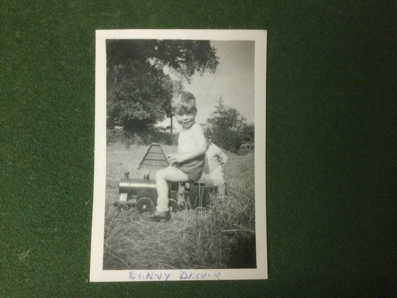 The wooden train The wooden train by John The Pump, on Flickr |
|
weary
Part of the e-furniture
Posts: 290
|
Post by weary on Apr 8, 2022 20:25:17 GMT
You haven't changed a bit!!  |
|
|
|
Post by flyingfox on Apr 9, 2022 6:38:54 GMT
Better looking then!
regards
|
|
dalboy
E-xcellent poster

Posts: 235
|
Post by dalboy on Apr 9, 2022 9:36:59 GMT
When John was a lad, his dad made him a ride-on train - it clearly sparked a lifelong interest. In turn the next generation thrashed it round and round, and now it's the turn of the third generation to have a go at wrecking it. It did need a bit of repair before the latest outing. A wheel had disintegrated, so a new one was made from some old timber rescued from a dead wardrobe. John still has the 1930s Myford lathe that turned the original wheels - his first lathe he got (from his dad) when he was six! And some old carbon steel tools were found, again the same as would have been used before. So a vintage repair all round. Who knew you could turn wood in an engineer's lathe? DSC_0074 by Wilf, on Flickr DSC_0076 by Wilf, on Flickr I don't think the loco's still in ticket, so no attempt was made to put a fire in it. Wilf If that was brought from a shop today it would not last anywhere near as long. Great job on keeping it going. Having made four wooden locos one being a ride on two as just toy trains and the last as a display model I can only hope that they last as long as this one |
|
|
|
Post by Jim on Apr 10, 2022 5:32:59 GMT
The hobby bites one early, here it is about 1944 and a very young Jim is already off on a railway adventure. |
|
johnthepump
Part of the e-furniture
Building 7 1/4"G Edward Thomas
Posts: 493
|
Post by johnthepump on Jul 4, 2022 20:54:02 GMT
I haven't posted much recently, one reason is that my device had run out of space. setting things up on the replacement has taken a while. A little job I was asked to help out with was a missing bracket from a small motor bike. The bracket had broken and taken to someone for repair and they had then misplaced it. As the part was obsolete and therefore unavailable there next door neighbour said he new "a man who can"  June 2022 June 2022 by John The Pump, on Flickr  June 2022 June 2022 by John The Pump, on Flickr |
|
johnthepump
Part of the e-furniture
Building 7 1/4"G Edward Thomas
Posts: 493
|
Post by johnthepump on Jul 5, 2022 18:17:57 GMT
Another little job yesterday, one of our members and a good friend who is restoring a 5"G. 9F has a lot of problems with the paint blistering on the boiler cladding. the problem was compounded when the cladding was sent for sand blasting during this process one of the dummy washout plugs was lost. I do not want to details only to say the cladding is now in good hands and no doubt will return in good condition. To help speed this job on I set to and made a couple of these little parts. The OD is 10.7 mm. and the square is 3.17 mm.  04.06.2022 04.06.2022 by John The Pump, on Flickr |
|
uuu
Elder Statesman
your message here...
Posts: 2,807
|
Post by uuu on Jul 6, 2022 7:39:32 GMT
Having seen the little bracket during construction I can report what a tricky little thing it was. Apart from getting the shape right, and all the folds in the right place, there's a tiny welded brace in the corner, which must have taken a very light touch with the electrode.
Wilf
|
|
johnthepump
Part of the e-furniture
Building 7 1/4"G Edward Thomas
Posts: 493
|
Post by johnthepump on Jul 18, 2022 10:11:22 GMT
Another little job a week or so ago. I made a puller to remove a Gib key that held a 4 groove pulley on the half speed shaft of Petter PU4 petrol engine, twin cylinder horizontally opposed which is quite rare, it was used to drive a compressor as part of an air start system. This part of Men in Sheds preservation and restoration project. The engine was put on its side and the recess in the pulley were the key is was given a good soaking with penetrating oil and left for a week. This engine had a cylinder head missing, the exhaust and fuel tank rusted out. Slowly a team member is working on it, but occasionally he asks for a little help with a few things that can only be made in a workshop. The round part of the Gib key puller was made from a piece of material from that box under the bench where it was resting have been used and modified several times in the past the square link I made out of gauge plate and the other part out of 10 mm plate and the TIG welded to the body.  31.05.22 31.05.22 by John The Pump, on Flickr The puller work well, but there was a problem getting the pulley off the shaft in spite of the fact I had made a puller to that job, so it was decided the those involved should meet in the Pumphouse the following evening. So the engine was loaded up in my SUV. 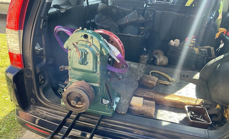 31.05.22 31.05.22 by John The Pump, on Flickr Once in the workshop the pulley was removed quite easily, the need for all this was to remove the front cover to enable access to the internal bolts holding the top part where the governor is housed and this was completely seized. Once taken apart it was found the governor shaft was seized in the housing, this was freed up with a little heat and it all came apart and checked over, one end of the governer shaft was a little worn so it was turned down by a few thou. and the new part in the photo below was made to suit. The only thing left to do was to make a 2 replacement parts which were severely rusted away and a few 3/8" BSF nuts. Note the building was in a very bad state of repair and leaking badly.  06.06.22 06.06.22 by John The Pump, on Flickr John. |
|
johnthepump
Part of the e-furniture
Building 7 1/4"G Edward Thomas
Posts: 493
|
Post by johnthepump on Sept 16, 2022 20:15:38 GMT
Back working on my loco build 7 1/4"G Edward Thomas. Work has started on the valve chests and these have been part machined with more done to the left hand one. I had these casting but not the covers, these are not available separately, so I had to source some cast iron to make them out of having material sent to the Island can be costly so I decided to see what I could find locally. With a cardboard template in hand I visited my local garage, the mechanic who was on his lunch break at the time walked over to a 40 gallon drum reached in and pulled out a brake disc, he told me this was off a transit and was the largest they had available.  Worn brake disc Worn brake disc by John The Pump, on Flickr With a little bit of work with an angle grinder and hacksaw I managed to recover pieces big enough to make the covers out of.  Brake disc segment Brake disc segment by John The Pump, on Flickr I have to thank Wilf for his help and encouragement with this project, we could have just made a flat plate but the drawing shows a ribbed cover. Wilf drew it up and produced the G codes to machine the pockets leaving the ribs. Once the basic rectangle was milled and the fixing holes drilled, the job was moved to the Myford and set up, the thickness was reduced by 1/32" leaving the centre boss, then the thickness was further reduced 1/4" to just inside the narrow sides, from here a 6 degree angle is required up to the centre boss. I found that this could not be done using the top slide at 6 degrees as the handle is over the cross slide, the answer was to use the top slide off my Myford ML2 which is side lug mounted.  Valve cover machining Valve cover machining by John The Pump, on Flickr It was then onto the Micro mill for the pockets  Valve chest cover milling Valve chest cover milling by [a href="https://www.flickr.com/photos/137901083@N08/"]John The Pump[/a], on Flickr Then it was back onto the mill to remove arc shape left on the long sides and a final clean up.  Finished valve chest cover Finished valve chest cover by John The Pump, on Flickr |
|
uuu
Elder Statesman
your message here...
Posts: 2,807
|
Post by uuu on Sept 17, 2022 12:49:19 GMT
Now we've just got to do the other one. Although there's a few bits to do on the cylinder first, while it's still mounted at the right orientation in an angle plate.
And, before anyone asks - yes, the mounting holes are rather uneven - but that's to miss the steam passages, valve spindle etc, in the layer beneath. They're even more off-pitch than on the drawings, because John's castings don't match up, introducing additional constraints. The boss isn't quite in the middle (deliberately) either.
Wilf
|
|
|
|
Post by Roger on Sept 24, 2022 18:45:15 GMT
That's a cracking job and a clever source of material, what a good idea.
|
|
johnthepump
Part of the e-furniture
Building 7 1/4"G Edward Thomas
Posts: 493
|
Post by johnthepump on Dec 14, 2022 17:12:39 GMT
It turns out not all connecting rods are made of metal, here is one I got talked into by my sister.  28.11.2022 28.11.2022 by John The Pump, on Flickr Most of the fitting work was done by hand, but I needed as nice transition from the handle diameter to the socket diameter of the spade, I managed to get it set up with only 10 thou run out not bad for wood.  28.11.2022 28.11.2022 by John The Pump, on Flickr There is some progress on my No.4 all be it slowly, I will try and post an update shortly. |
|


