|
|
Post by Roger on Oct 12, 2016 13:04:05 GMT
Very nice work indeed! I too use MDF on occasion, but as you've hinted, if it becomes wet, even with quite thick cutting oil, it 'gives' and you'll find that the clamping force disappears and it can move. I've also set fire to it dry on occasion when the cutter was past its best!
I use Perspex for the same job if I'm using cutting oil, it's also cheap but it's stable unless it gets very hot.
|
|
|
|
Post by 92220 on Oct 12, 2016 16:35:11 GMT
Never thought of Perspex because the MDF I get is free, but I agree it is definitely a better material than MDF for this use. Where do you get your perspex from? I've had a look on the web and the price seems to vary a lot!
|
|
|
|
Post by Roger on Oct 12, 2016 18:27:24 GMT
Never thought of Perspex because the MDF I get is free, but I agree it is definitely a better material than MDF for this use. Where do you get your perspex from? I've had a look on the web and the price seems to vary a lot! I generally get it from eBay, but as you've noticed, you have to look at the total cost to get the best deal. You may be able to pick done up from a local plastics supplier though and save the carriage |
|
|
|
Post by 92220 on Oct 12, 2016 21:59:13 GMT
Thanks Roger. I will investigate!
|
|
|
|
Post by doubletop on Oct 15, 2016 8:50:04 GMT
I was given some 1/4" paxolin which is ideal and its stable, accurate, resists the oil and heat. I can imagine perspex melting in some circumstances.
Pete
|
|
|
|
Post by Roger on Oct 15, 2016 10:17:59 GMT
I was given some 1/4" paxolin which is ideal and its stable, accurate, resists the oil and heat. I can imagine perspex melting in some circumstances. Pete Hi Pete, It certainly can melt, but it only does so locally, so you don't lose the support where the clamps are. That's the real problem with MDF which acts like a sponge. I think any of the resin bonded paper boards would do the job well too. I only use Perspex because it's so cheap. |
|
|
|
Post by 92220 on Oct 31, 2016 17:25:21 GMT
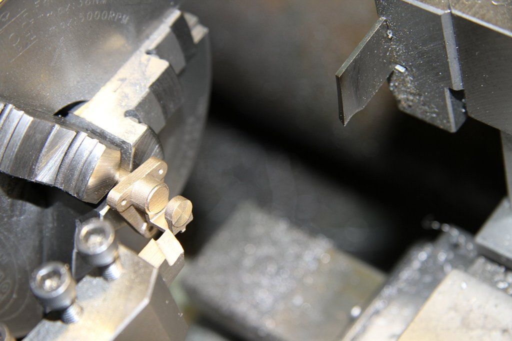
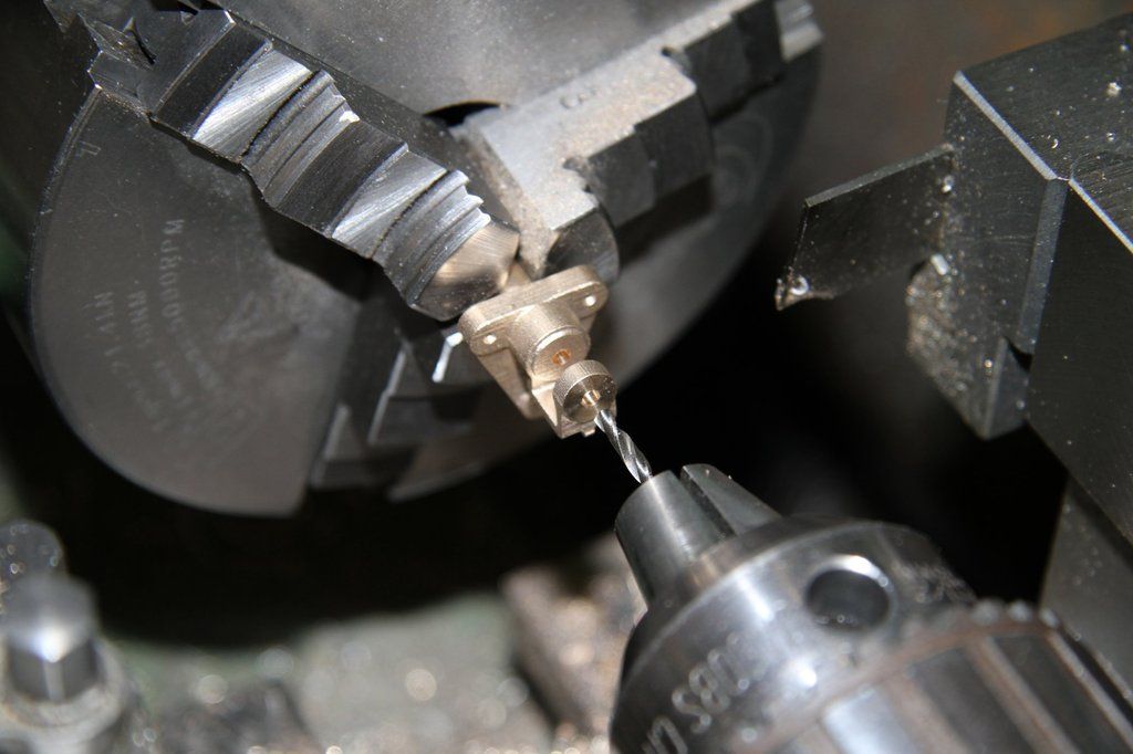
Although I haven't posted anything for a while, I have been quite busy. I collected a set of BR tender spring pivot brackets and brake hanger brackets, from Adam Cro, at the Midlands Exhibition. These have got to be machined and riveted to the tender frames before the stretchers can be riveted in place. I have made a start by machining the Spring Pivot Brackets. They are not the easiest of items to machine because of their shape and size, so I have done a 'How to' to help others, and also to check how easy the castings are to machine, as they are prototypes. First of all, the castings are up to Adam's usual high standard. So much so that when I checked the overall dimensions for making the jigs, I found they are accurate within just a couple of thou. They are an exact scale miniature of the real thing!! The first job is to cut off all the sprues. The next job is to machine the back mounting face to act as a datum. The jig for this is very simple - a piece of 1/2" square mild steel about 3 to 4" long, machined down to 7/16" square. To hold the casting in place I machined up a small bridge piece to clamp it to the 7/16 mild steel bar. Note that one corner of the Bridge Piece has been filed away. This is to allow room to get a vernier in to measure the thickness of the mounting lugs, while the casting is still clamped in place. 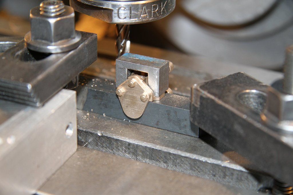 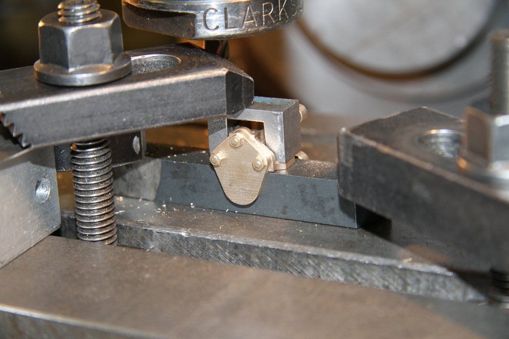 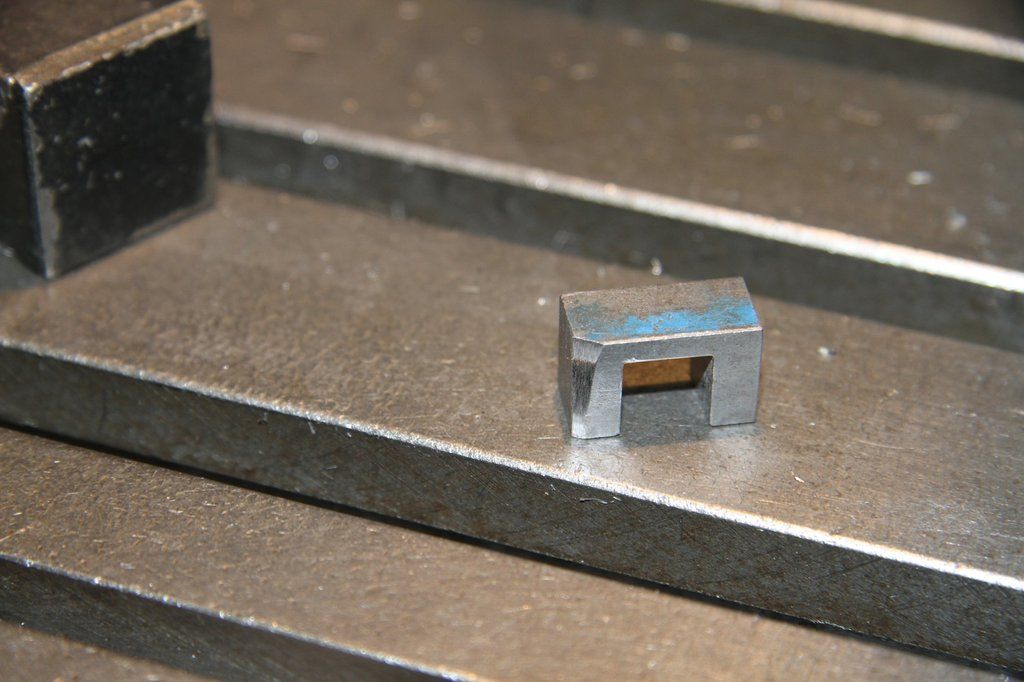 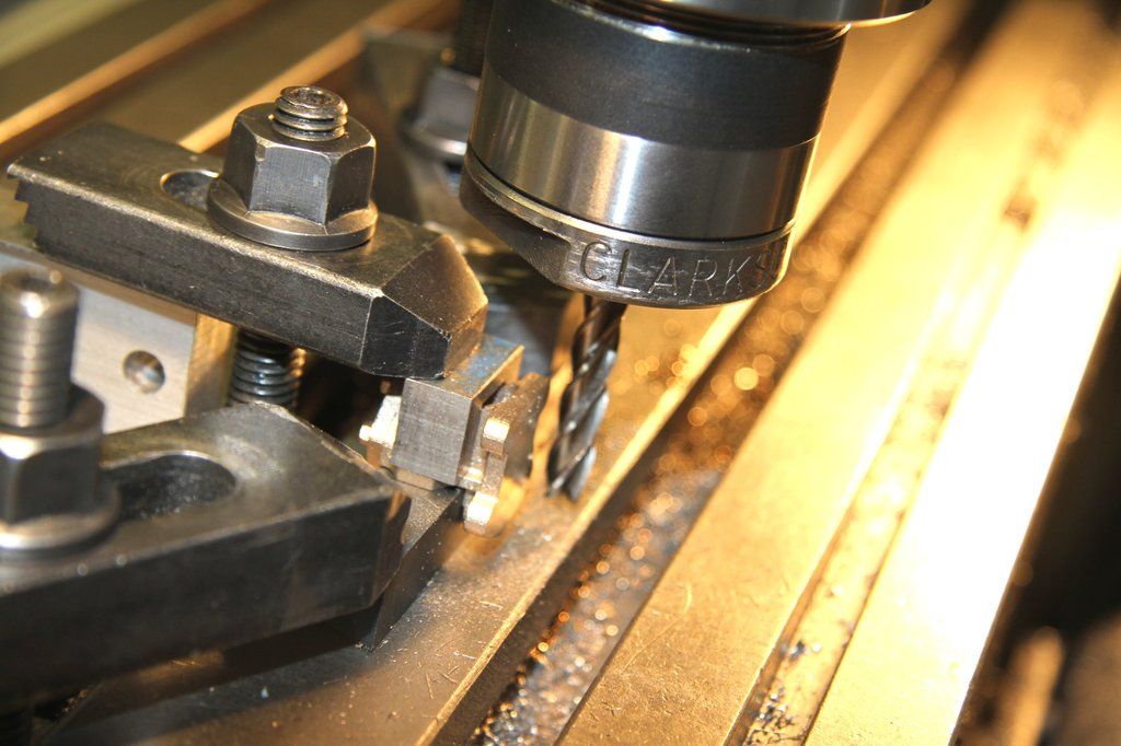 The 7/16" mild steel bar is clamped at each end, to the milling table, and set exactly parallel to the direction of travel. Because the castings are so accurate, the rear inside cast face (where the spring sits) can be used as a location face, and it can be clamped down on the underside of the casting, using the little Bridge piece, to clamp on the side lugs, like in the photo. The rear mounting face is machined using a long series 1/4" or 6mm endmill. This enables the face to be machined without any up/down movement of the table. A number of light cuts were made until the thickness of the mounting lugs was reduced to 0.155" (scale 1.3/4"). The cast location face will be skimmed down later. bronze can easily work harden if the cutter isn't sharp. I used a brand new cutter and with light cuts, ran the table so that the cutter down cut (also called climb milling)). This is not normally recommended practice, but on soft metal and with light cuts, actually puts less stress on the machine, cutter and component. It also ensures that the cutter cuts and doesn't rub and work-harden the metal. The next job is to drill the 2 top mounting holes. Not all 4 because a No.1 centre drill is no long enough to hold on the full cylindrical shank, to get to the centres of the lugs. I made up a simple jig to hold and drill the top 2 mounting holes. 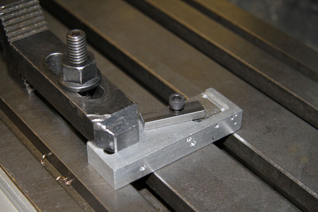 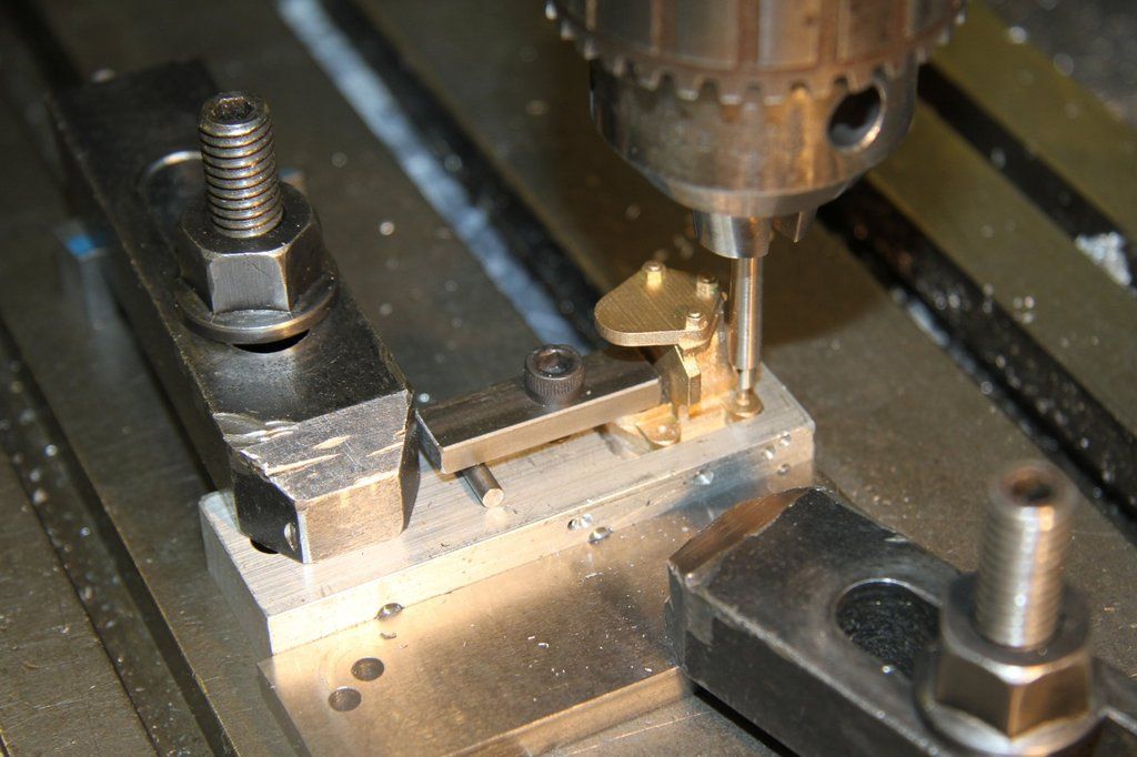 Note the extended centre drill. It is a centre drill Loctited into a piece of 3/16" silver steel and the piece reset in the Griptru chuck and carefully centred so that the hand of my 0.0002" dti doesn't move. When I then skimmed the outside of the silversteel to just clean up and be concentric with the centre drill. I then parted it off and I have a long centre drill that I can use with confidence. A casting was placed in the jig and manually pushed against the end and right hand sides of the jig. It was then clamped in place, the 2 top lugs centred, and then drilled 3/32" dia. Once these were all drilled I made a jig to locate on the 2 holes just drilled, using 3/32" rivets to locate, and have 2 holes in the correct positions to drill the remaining 2 mounting holes. The casting was held in the jig, by hand, and the holes drilled. 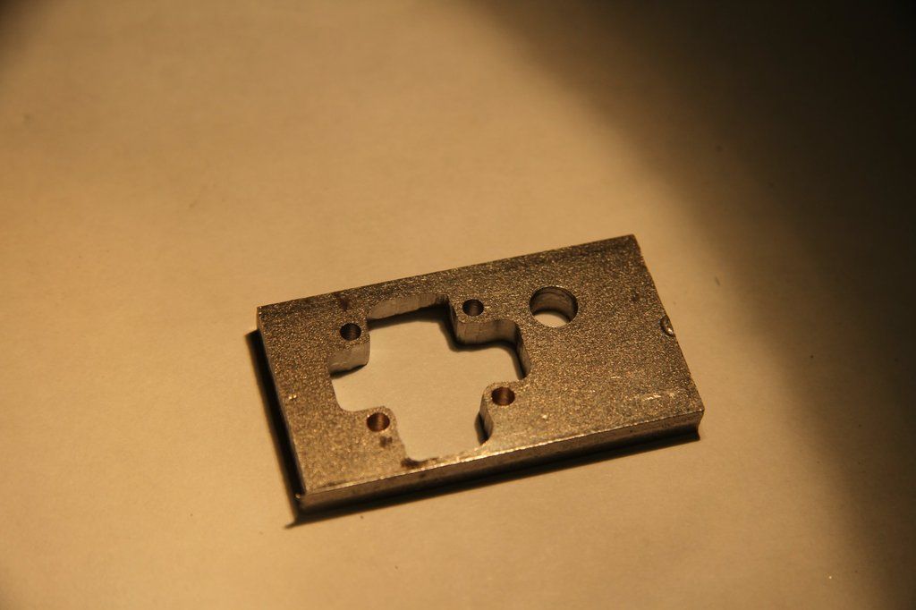 Note: Chamfer the sharp edge on inside of the jig that is closest to the thin, angles webs that go from the back plate to the front cover. These are very thin and very easily damaged, so best not to take a risk. 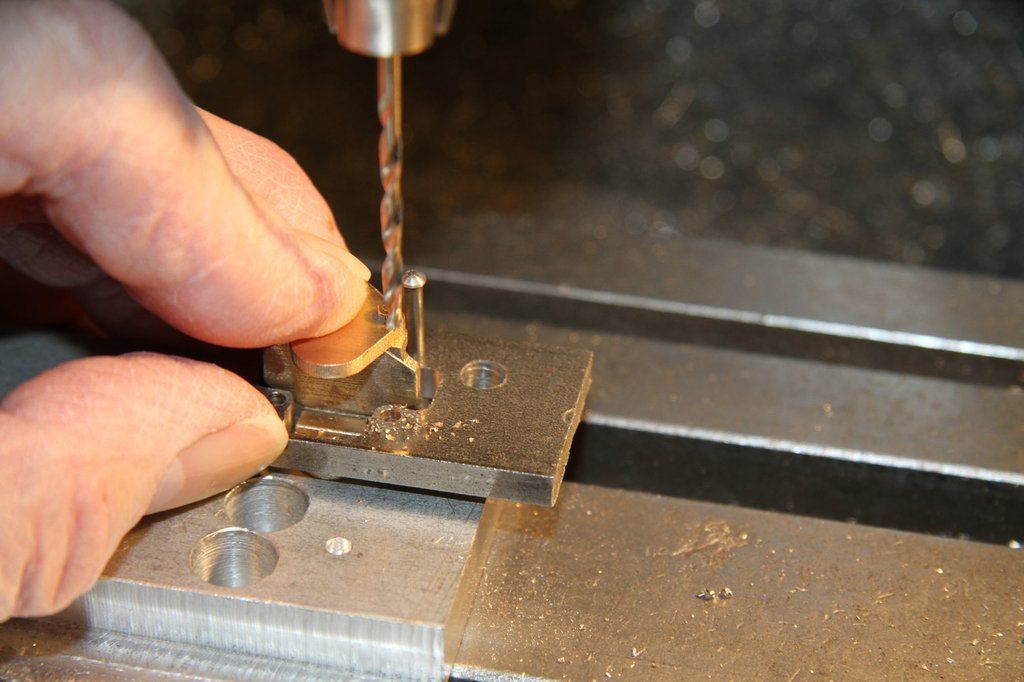 The next job is to machine the faces that come in contact with the spring leaf edges. Again, another simple jig was made to hold the castings. First off, I turned up 4 fitted bolts - 3/32" dia, threaded 7BA, and just the right length that half nuts could be used with no thread protruding. Next I made the holding jig. A piece of scrap 1" square aluminium, about 1.1/2" long, came in handy for this. It was machined to an 'L' shape. My machine vice has dowels fitted to the underside, to locate in the mill table tee slots. This gives me a fixed jaw that is within a though over the length of the jaws, so no setting up required. I set the quill head so that the centreline of the cutter was in line with the face of the fixed jaw, using my usual method. I have a piece of 3/8" silversteel which I held in a 3/8" collet in the Myford, and turned a couple of inches down to 0.250". It would actually have been easier to use a 1/4" collet but that would have meant spending money, and I already had a 3/8" collet. Actually, any size will do; even 1/8". All I do to locate the face is to hold a piece of cigarette paper against the face and slowly bring the table over until the paper is just nipped by the 1/4" bar. The paper is 0.001" thick so I just have to move the table 0.126" to get a true position, but any method of finding the face can be used. The 'L' shaped piece was held in the vice jaws, with a piece of 1/4" silver steel as a spacer to provide a gap underneath for the drill to break through. I also, always, pop a scrap is sheet steel under to stop the drill damaging the vice, or breaking the drill, if I'm too enthusiastic! The holes were accurately drilled for the fitted bolts, using the DRO, but if you haven't got a DRO, careful reading of the leadscrew graduations will do the job. The hole positions do need to be accurate if the frame plates have already been drilled. If not, you are in luck. Adam has cast in centres which are accurate enough to use. Then use the castings to spot the frame plates. You could say " Why not use the frame holes to drill the castings. The problem with that is that the casting mounting lugs are of such a size that if the holes are even 5 thou out, it will be obvious. It would also be extremely difficult to clamp the casting, in the right place on the frame plate due to the shape. There is really no surface that can be clamped on to. 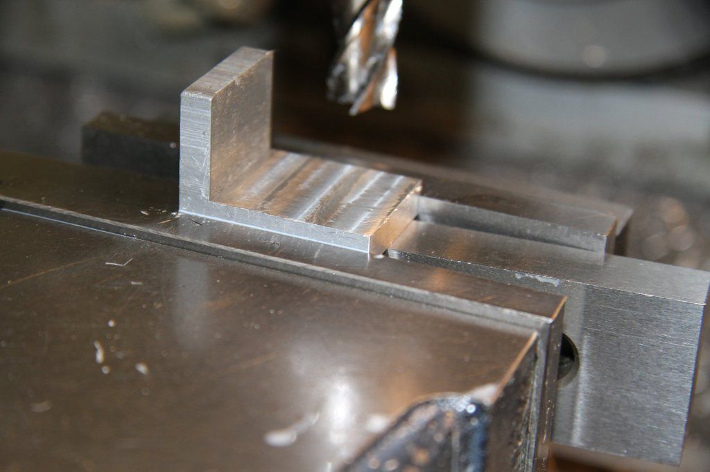 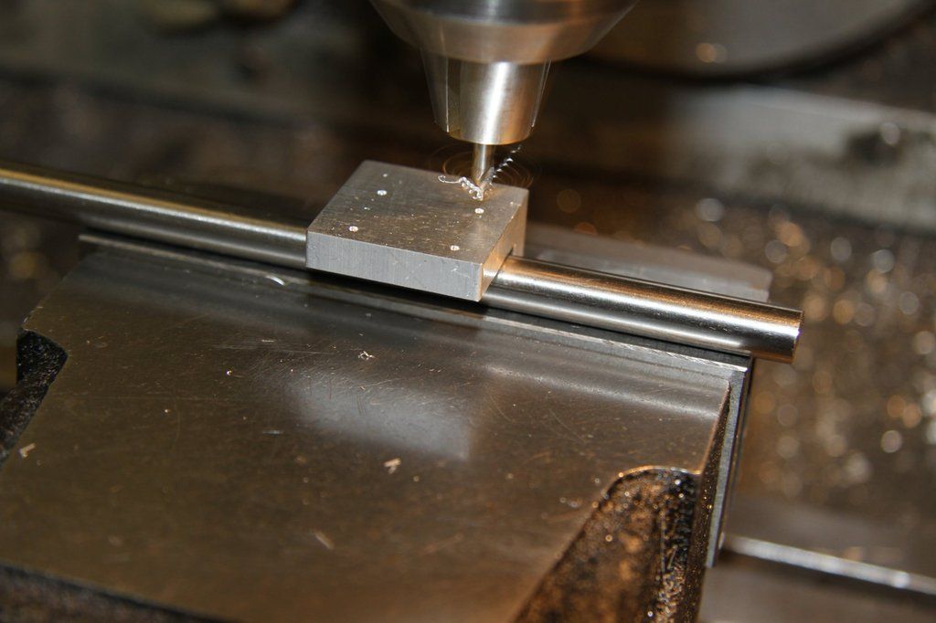 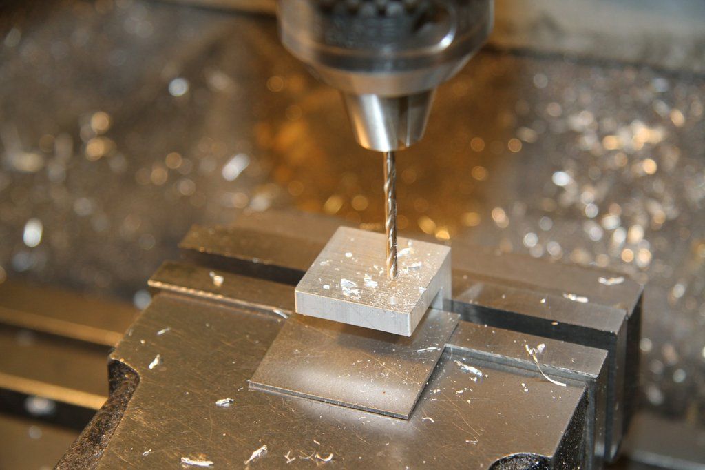 Once the L-shaped jig has been made, set it up on the mill with the drilled face towards the front and exactly parallel to direction of travel, and sticking upwards. Clamp it. Once clamped, then set 2 pieces of, say 1/8" thick bar against the drilled face, and one side. When clamped down, these will act to locate the jig exactly, every time it is removed and re-clamped. 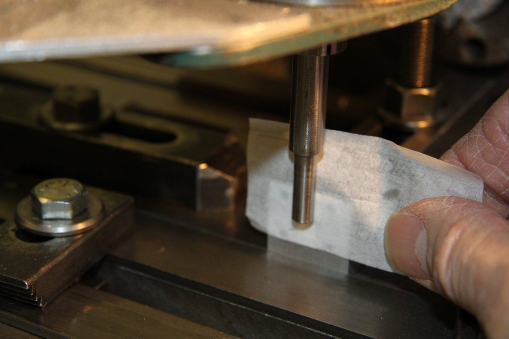 The rear inside face that faces the spring leaf edges, now has to be skimmed. The mounting lugs have already been machined to 0.155" thick. You now need to skim the slightly raised rectangular area on the rear inside face. You will only need to remove a few thou, so take it easy. Using a 1/4" or 6mm endmill, bring it down to just touch the underface of the casting. Back off by about 4 or 5 thou and move the table out so the cutter just kisses the rear face. Then take a 3 thou cut across the face, and measure. At most, you will need to take another 5 thou to bring it to 0.166" thickness to the back mounting face. While the casting is in the jig, take a light skim across the underside of the casting to just clean up (top face when in the jig). See the photo.  The next job depends on how close to scale you want to go. Adam has provided a very realistic, cast nut in the top of the casting. This nut would be what holds the spring pivot into the casting. If you want to keep this nut then you need to provide a blind hole, about 0.1" to 0.125" deep, and 0.125" dia to fit the spring pivot. The spring pivot will have to be machined to match whatever dimensions you end up with. You can produce this blind hole any way you find convenient. However, there are also the 2 holes to drill for the spring leaf clamping hooks. Although only one is used per casting, both holes are drilled so that they can be used either side of the tender. I spent a little time thinking about the pivot hole and decided that I would try machining as per full-size and drill right through. To drill these holes I took the jig off the mill and mounted a casting to the jig, the proper way up, with the cast Pivot Locking Nut upwards. I then remounted the jig on the mill, against the location strips. Once clamped down, I then set the quill centreline to line up with the casting mounting face of the jig, and set the mill DRO to zero. You can do the same with the leadscrew thimbles. I then moved forwards 0.387". I then removed the jig and mounted a casting to it, the right way up, with the cast pivot locking nut upwards. I then located the centre of the casting using my cigarette paper method to just touch each side of the casting. Once I had this centre set I checked the readouts were both zero. A No.1 centre drill in the chuck, was brought down to just touch the centre of the cast nut to check the accuracy of setting up. The casting is so accurate that if the centre spot isn't in the right place, then you need to recheck your setup. I then centred the cast nut, quite deeply. At the same 0.387" 'Y' axis setting (in-out), I moved the table 0.296" on the 'X' axis each way (lengthways), and spotted the horizontal lugs. The centredrill was then swapped for a 3/32" drill and the 2 centre spots in the lugs, drilled through. The drill was then swapped for a 7/32" slot drill. The cast nut was then gently machined away by feeding the slot drill down until it just cleaned up a full circle on the cast surface. The slot drill was swapped for the No.1 centre drill again and this centre hole re-spotted. The centre drill was swapped for a 3.3mm drill and a hole was drilled right through. The 3.3mm drill was swapped for a 3.4mm drill and the hole opened out. It ended up as an accurately drilled 3.4mm diameter. This is a bit smaller than scale but it leaves a good land for the spring pivot and nut to clamp on to. This is copies full size and is in fact easier to machine than the blind hole described earlier. It's probably taken longer to write this than to actually machine it! As these castings are prototypes, I am working with Adam on the easiest way to machine them. He says he will look at removing the cast nut and replacing it with a flat surface with a cast-in centre for drilling. This should make machining a doddle as it would only be a case of locate the cast-in centres and drill through. No centre drilling required! Setting the quill centre line to coincide with the edge of the casting: 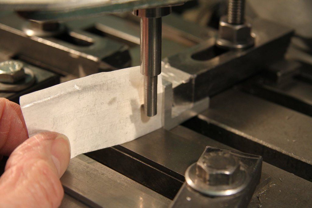 Note the spacer piece under the front cover, to support the casting during drilling: 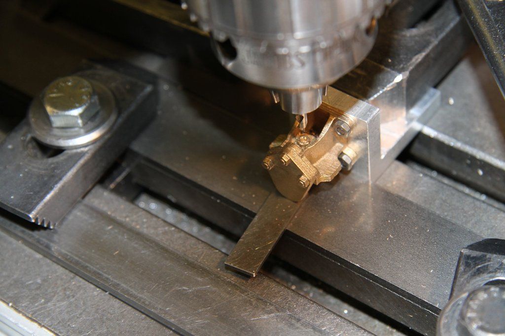 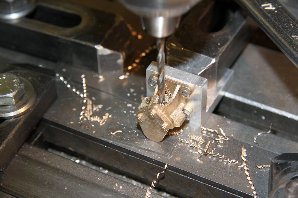 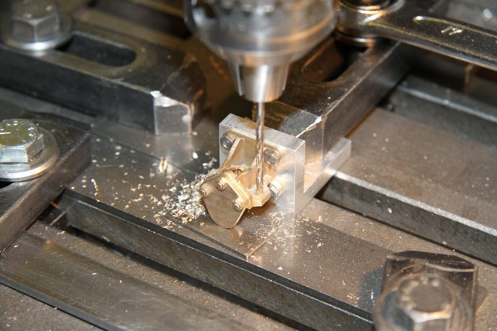 I took this photo to show how accurate Adam's castings are. I did not find the centre to drill by trial and error. I used the drawing dimensions and the 7/32" slot drill just cleaned up the surface, dead centre! Well done Adam for getting the drawings so accurate, and Mike Jack, who did the casting. 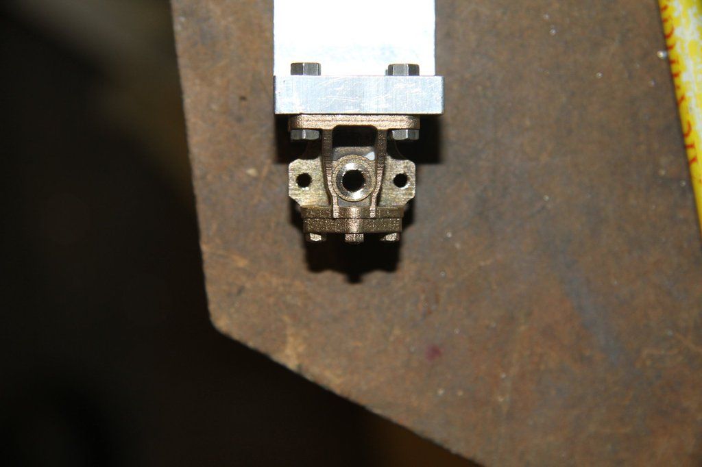 The last job is to fettle where the casting sprue just encroached on the side of the mounting face, and to de-burr the holes. That's it. The castings are machined and ready to rivet in place. Before this, though, it is a good idea to machine the tender brake hanger castings as one of the rivets is common to both the spring hanger bracket and the brake hanger bracket. They will then be riveted to the frames, as a pair. And here is the results of the week's work! 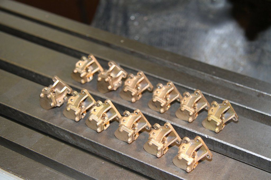 |
|
|
|
Post by Cro on Oct 31, 2016 18:50:44 GMT
Bob,
They have come out great, thanks for the detailed explanation of how you did these.
Adam
|
|
|
|
Post by niels on Nov 2, 2016 18:21:35 GMT
Hello
Am new here and like 9Fs.
Have seen some in action and has been on footplate of one in Swindon museum.
Am playing best CME of all time in England.
The limit must always have been the loading gauge making inside cylinders an option.
Russia, with a much bigger loading gauge, have had no inside cylinder engines.
I have read somewhere that the 9F cylinders was not the same as the Britania ones due to crosshead-front crankpin clearance issues.
My first question if someone care to answer is what is the cylinder centre distance?
On a Midland Compound where conrods are inside the coupling rods it is 6 feet 3.
My plan is to design a time machine and go back to let us say 1930 and bribe me to the job mr Stannier got.
A locomotive familly with 5 feet wheels and widebox boilers will do very well.
For high speed a 4-8-0 three-cylinder compound with frontwheel drive can do what lot of other locomotives did.
For freigth and slow passengers a 4-8-0 with a big low-pressure cylinder between frames and a single high-pressure on one side will be an economical maid of all work.
Smaller units of LNWR Prince of Wales size and Moguls both as two cylinder compounds are the small familly locomotives.
The only thing standing between me and ethernal fame is the lousy weigth diagram of a 9F i have.
Is there somewhere in engineering periodicals a better resolution drawing and will someone tell me:What was the intercylinder distance of a Britannia and a 9F?
A Holden B12 with a big lowpressure inside and a single high pressure on one side will look very well also i think.
Kind regards
Niels
|
|
|
|
Post by 92220 on Nov 3, 2016 10:20:10 GMT
Hi Niels.
Welcome to the forum. You asked what the cylinder dimensions are for the 9F and the Britannias. These are the 9F dimensions copied from the original British Railways drawings, but I don't have the Britannia dimensions. I'm sure someone else can supply them though.
9F dimensions:
Cylinder centres = 6 feet 8 inches (2032mm)
Piston Valve centres = 7 feet 4 inches (2232.5mm)
Piston valve centre line is 1 foot 10 inches above the cylinder centre line 508mm)
Cylinders are 20" diameter (508mm)
Piston valves are 11 inches diameter (279.4mm)
Hope that helps.
Bob
|
|
|
|
Post by niels on Nov 3, 2016 12:45:56 GMT
Thank You Bob
The Pacific killer 9F derivative 4-8-0 with drive to first coupled axle can have a cylinder distance of 6 feet 3 .
Present 9F have 6 feet 8 and 20 inch bore and lines where 9F can pass will also allow 4-8-0s having 22,5 inch bores.
A three cylinder compound with a high pressure 20 inch centre and two 22 inch outside can do the work of all British pacifics for less coal.
For max speeds less or equal to Britanias it will be even more economic to have a single 30 inch low pressure inside and single 20 inch high pressure outside.To even out railwear every second locomotive have it on starboard side.
Being a little short of the nessecary means for building a protype,I will scheme a 3D Gauge One version of the two cylinder compound variant.Based on Roger Thornbers work
Am looking forward to publish it here.
Niels
|
|
|
|
Post by 92220 on Nov 9, 2016 19:27:49 GMT
The Tender Spring Hanger Pivot Bracket castings are done, now it's on to machining the Tender Brake Hanger Bracket castings.
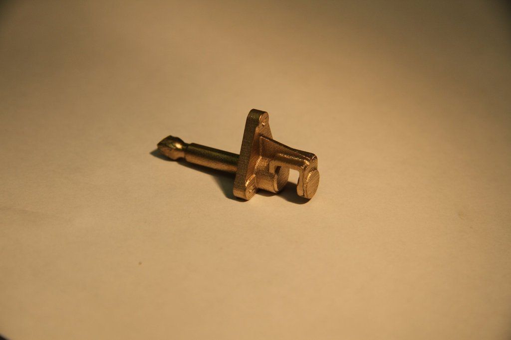
The first job is to cut off the ragged end of the sprue, and deburr the end. Cut the minimum off, to clean up, because you hold the sprue to do the next job, and also to machine the mounting face.
The sprue is 3/16" dia so if you have a collet that will hold it, use it. If not, set up in the 3 jaw chuck. Adam has designed the casting so that the sprue is exactly on the same centreline as the hole for the brake hanger pivot pin. The first machining job is to face the outer end to JUST clean up. Having faced the ends of all the castings, the next job is to centre the skimmed face with a No 1 centre drill. Gently does it so as not to put too much load on the casting which is quite thin. Only centre using the pilot drill, don't drill so deep that the 60 degree starts to cut. Then drill through with a 2.2mm drill to a max depth of 0.475". The 2.2mm hole can then be opened out to 3.4mm/0.134" dia to 0.475" deep. This should give you an accurate hole for the brake hanger pivot pin. Don't drill deeper than the 0.475" because you want to retain strength in the sprue, for subsequent machining. Do this drilling all at one setting so that you ensure all drills run concentric.
The next job is to make a jig to hold the casting to accurately drill the mounting holes if the frames are already drilled. If the frames are not drilled, then you can use Adam's 'cast-in' centres to centre the drill for the mounting holes, then use those holes to mark out the frames. The jig will also be used to machine the mounting face, and to bore the 7/32" dia hole for the head of the brake hanger pivot pin, in the back face of the casting.
First off, I found a piece of 1" x 1.1/4" x 2" aluminium. I set it up in the machine vice, to mill the ends square with the faces.
The raw casting:
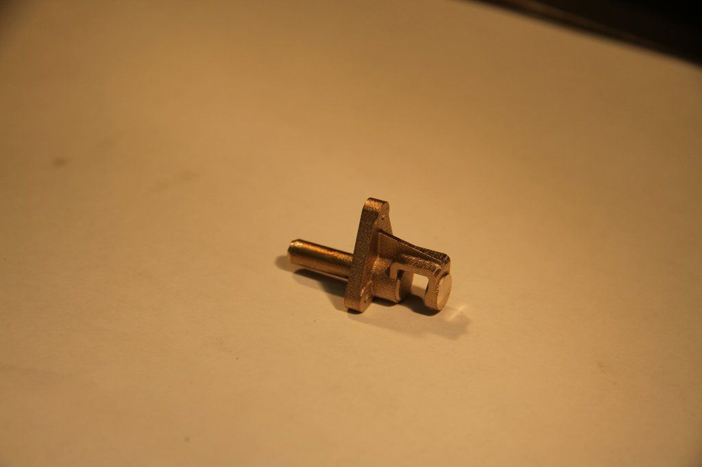
Casting with ragged end removed:
Skimming the outer face:
Casting centred and drilled for the brake hanger pivot pin:
The next job is to make the machining jig:
The block was then held upright in the vice, to machine and drill the end to locate and hold the casting.
Set the cutter centre to line up with the fixed jaw of the vice, and one side of the ally block. Measure the block and move the quill centre to exactly the centre of the block face. Zero the DRO or leadscrew thimbles. Centre drill the face No 1 centre. Here is a tip I learned as an apprentice draughtsman, when I did 18 months on the machines in the development workshop. Only centredrill the depth of the pilot of the centredrill. Do not drill so deep that the 60 degree part starts to cut. Next, take a new drill, around 2.5mm dia, to open up the centre hole. DON'T just push right on down. Even a new drill can wander. Drill a few thou deep and back off. drill a few thou more and back off. Do this again and again, just drilling a few thou at a time - say 10/15 thou at most. Drill down a bit further than the length of the sprue. When drilling the ally, use some suds to stop the swarf sticking to the drill flutes and forcing it off centre.
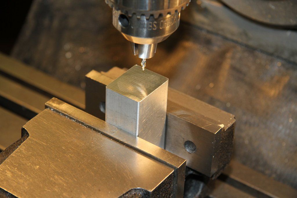
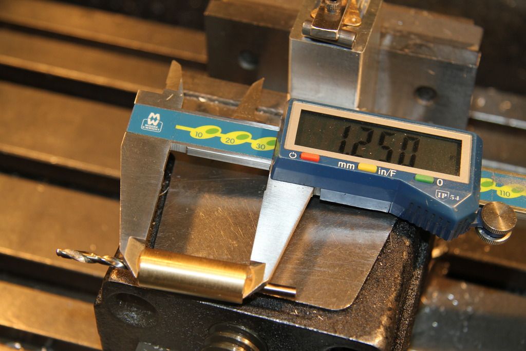
This method also works when drilling deep holes in the lathe. I did a trial drilling to get a photo to show how accurate drilling by this method can be. The photo shows a piece of 1/2" x 1.1/2" long brass bar that was drilled with a 2mm dia drill. Remember, that even a new drill will run out if drilling is too heavy handed. The bar was held in my Griptru chuck and set to run with no movement on the 0.0005" dial indicator. I drilled the bar using my "drill a few thou and back off" method. It didn't take too long to drill though. When I had finished, I reversed the piece of bar in the chuck and checked that the OD was running dead concentric again. I then slid the 2mm drill into the hole so that the shank stuck out, and set up the dial indicator on the shank. It ran concentric within half a thou over 1.1/2" length! That's how good the method works. When drilling deep holes, always use a new drill that is a bit bigger than the centredrill pilot for the first drilling. Once you have an accurate hole, subsequent drills, provided the cutting edge is sharp and not chipped at the corners, will follow the original drill path perfectly. That is, provided you still use the "drill and back off" method; though for these subsequent drillings you can drill deeper - say 30 to 50 thou each time, so you can open out to any size.
Measure the casting to determine the width of the recess:
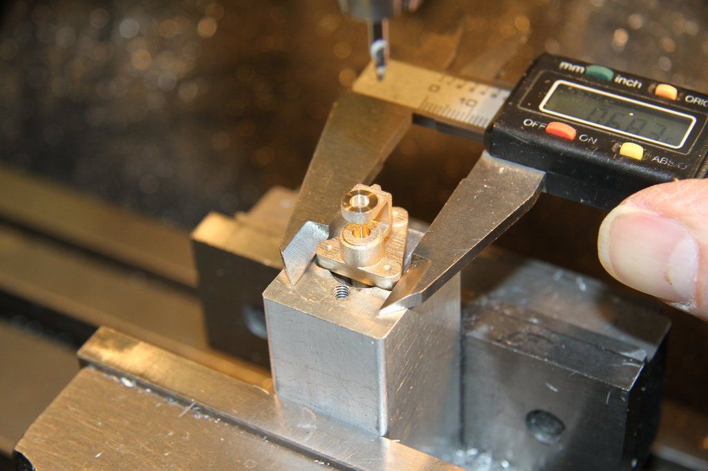
Checking the clearance between the front of the casting and the front edge of the recess, with feeler gauges:
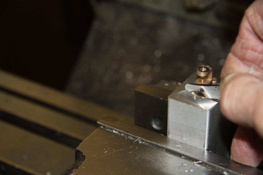
The finish machined jig:
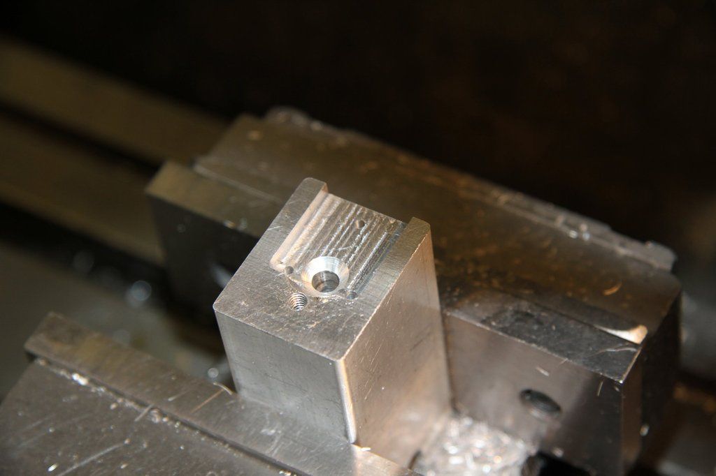
The tapped hole at the front of the jig is for a clamp bar to clamp the casting into the jig for drilling.
There are lots of photos so more to come.
|
|
|
|
Post by Cro on Nov 9, 2016 20:23:47 GMT
Glad they are going well Bob, look forward to the next update!
Adam
|
|
|
|
Post by 92220 on Nov 10, 2016 19:58:48 GMT
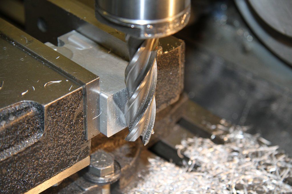
Back to machining the jig: Open the hole out to 3/16" dia. Check that all the castings will just slide in. If they won't, open the hole out to 4.8mm dia. Then they should fit in. Don't forget to use suds. Re-chuck the centre drill and centre the block to the brake hanger mounting bolt centres. i.e. move 0.066" towards the front of the mill. Then move 0.243" to one side and centre. Move to 0.243" the other side of the centre of the block and centre (0.486" total). Move back to the centre of the block - the zero-zero position (over the centre of the 3/16" hole). From 0-0, move up 0.487" to centre the top mounting hole. Next, chuck a 2mm dia (No.50) drill, and drill the block about 1/2" deep at all 3 mounting hole centres. Next, tap the holes 7BA x 3/8" deep. The next operation is to mill a recess for the casting to sit in. Measure the casting across the lower lugs. Using a 1/8" or 3mm slot drill, machine out a recess in the top of the ally block, that is about 1/16" deep, and smaller in area than the casting mounting face. Make sure you mill equally either side of the centre of the 3/16" hole. This is quite critical as the casting has to sit snugly in the recess, when finished. Measure how much smaller the recess is than the casting width and machine away half the difference, each side, to get an accurate, centred recess. Do this at the outer, open, end of the recess, for about 1/4" and check all the castings JUST fit in. Continue milling to open out the rest of the recess to this width. Mill down to 0.100" beyond the horizontal centreline of the lower mounting hole positions. This should be with the cutter centreline at 0.100" below the centre of the 3/16" hole. Next - countersink the 3/16" hole to 5/16" dia. This will also c'sk part of the lower edge of the recess. That doesn't matter. Drop a casting into the recess and it should fit in. It will almost certainly be a bit sloppy. With a feeler gauge, check the gap between the lower edge of the casting and the lower edge of the recess. Push the casting away from the lower edge as you check with the feelers, to get the maximum gap. I got the previous lot of photos out of order. The next photo is checking the gap between the edge of the casting and the edge of the milled recess: Take the cutter outside the recess, at the back, and lower it a further 1/16".(total depth of 1/8") Mill out the recess to exactly the same dimensions as before, except that the lower edge of the recess must be smaller by the amount measured with the feelers. i.e. if the feelers measured a gap of - say - 0.008", then move the milling cutter to 0.092" below the centre of the 3/16" hole (zero-zero position) instead of the original 0.100". Try a casting. If it fits, try all of them. If any don't fit, machine the lower edge by a thou at a time to get an exact fit. Next. Drill and tap a 4BA hole about 0.35" below the 3/16" datum hole ctr. This is for a clamp to hold the casting while drilling the mounting holes. A casting clamped in the jig and ready to have the mounting holes centred and drilled: 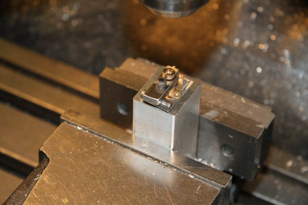 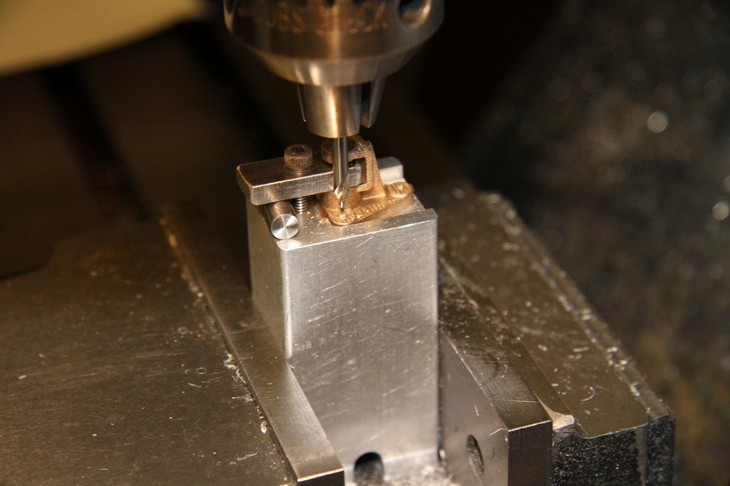 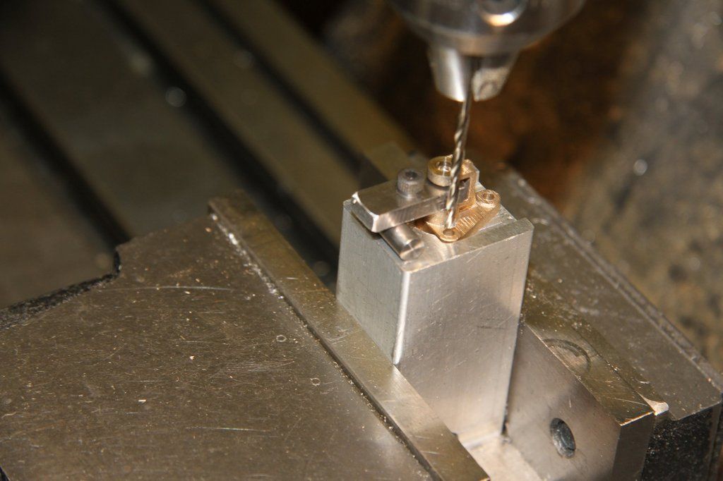 The next job is to machine the back face of the casting, to thickness. Chuck the sprue in the 3-jaw, with the back face about 5/16" from the chuck jaws. Use, either a 1/8" wide parting tool or, preferably, a 3/16" L.H.turning tool, in the toolpost, to skim the rear face of the casting. The face should be faced off down to the sprue diameter, until the thickness from the rear face to the inside face of the brake hanger bridge piece is 0.286" . Final cleaning up of the sprue will be when it is fitted into the jig to clean up and bore the rear face for the head of the brake hanger pin. Casting in the lathe, having the back face machined: 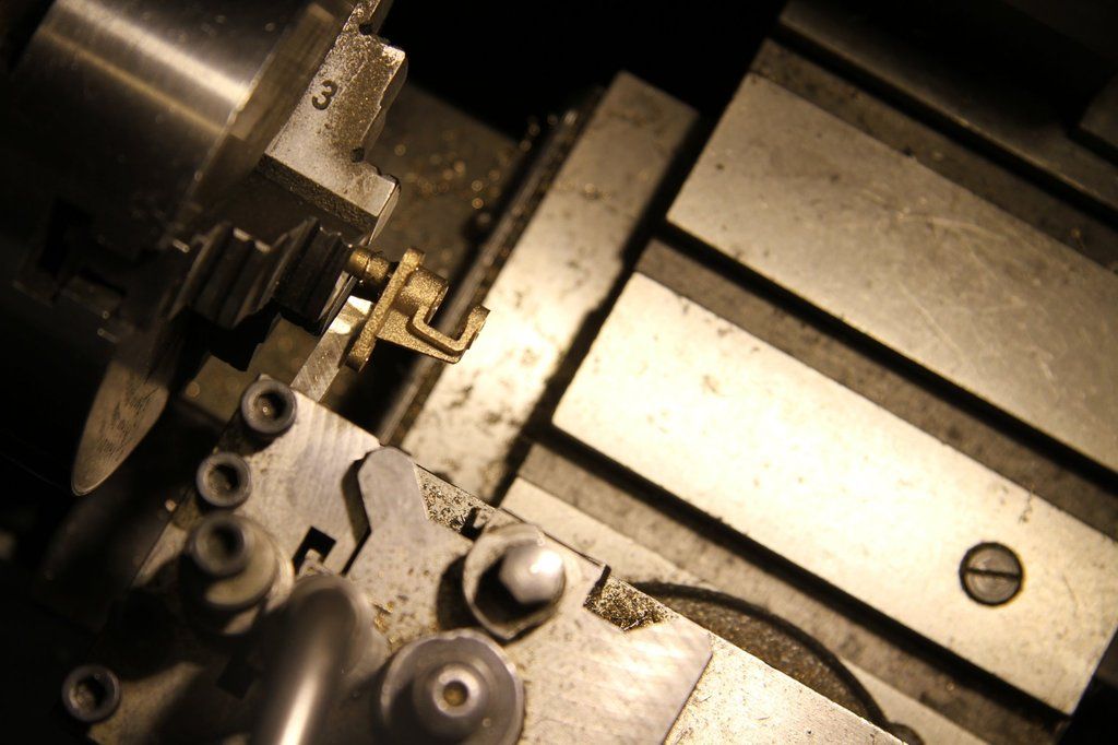 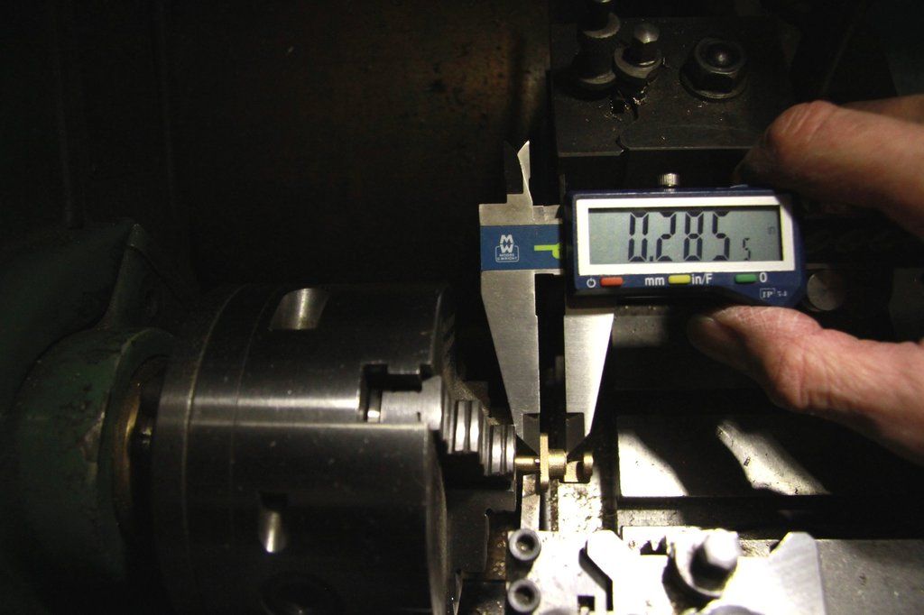 Once all the castings have had the rear face machined down to the sprue, they are ready to be parted off from the sprue. This is where it looks as if it is going to be rather difficult due to the shape of the casting. Actually it is very easy. Next, the 3.4mm hole has to be extended down into the sprue to a total depth of around 11/16" 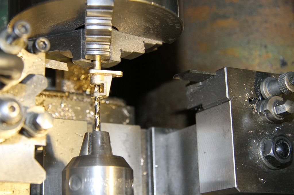 The next op is to part off the casting from the sprue. This is the tricky part because the casting is such an awkward shape that it is not safe, or even possible, to part off in the normal way - waiting to catch the parted off piece in the fingers. So - reverse the 3.4mm drill in the tailstock chuck with about 3/4" to 1" sticking outside the chuck jaws. Advance the tailstock until the drill shank has gone into the casting about 1/2". Set the headstock speed to around 425/450 rpm. With a sharp parting tool, part off the casting from the sprue. The tool should be set to just touch, or just be clear of the rear face, which will be cleaned up when the 7/32" flat-bottomed recess is machined in the rear face. The drilling jig will be modified to hold the casting for this job. When parting off, advance the tool VERY gently until the point of 'break-through'. The casting just rotates down and slightly away from the tool. As to when the cut will finish, with mine, the tool squealed a bit when cutting, and just before it broke through, the squeal stopped. 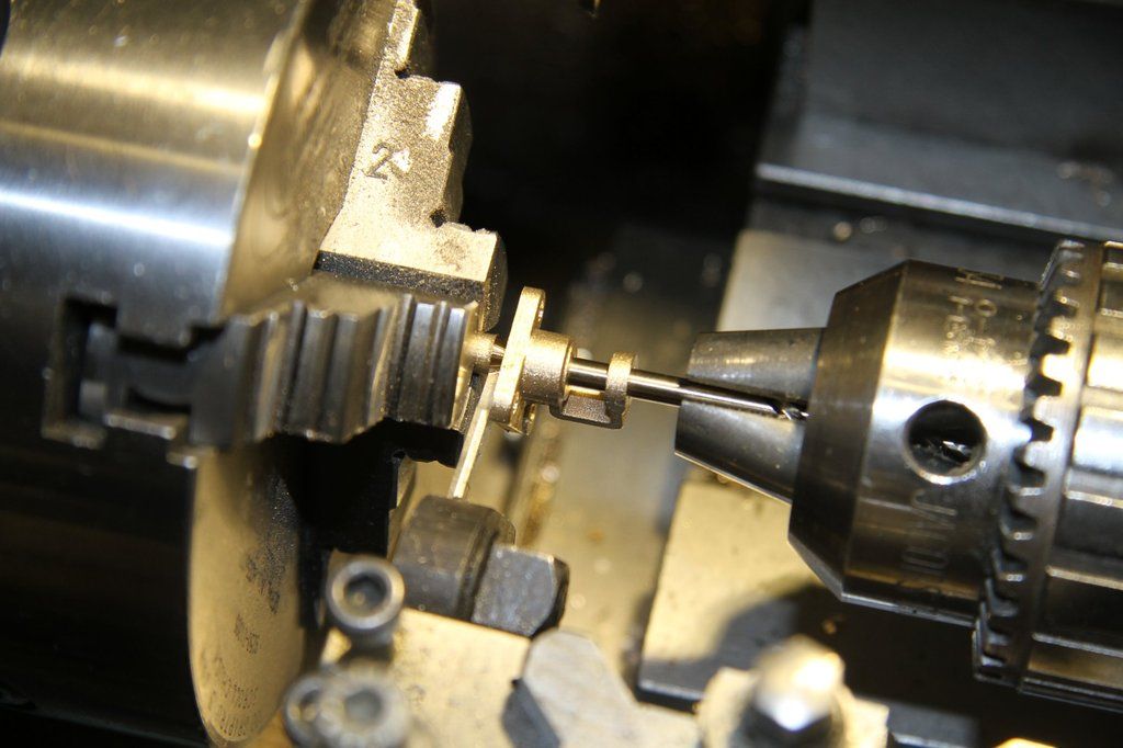  Photo of the parted off casting: 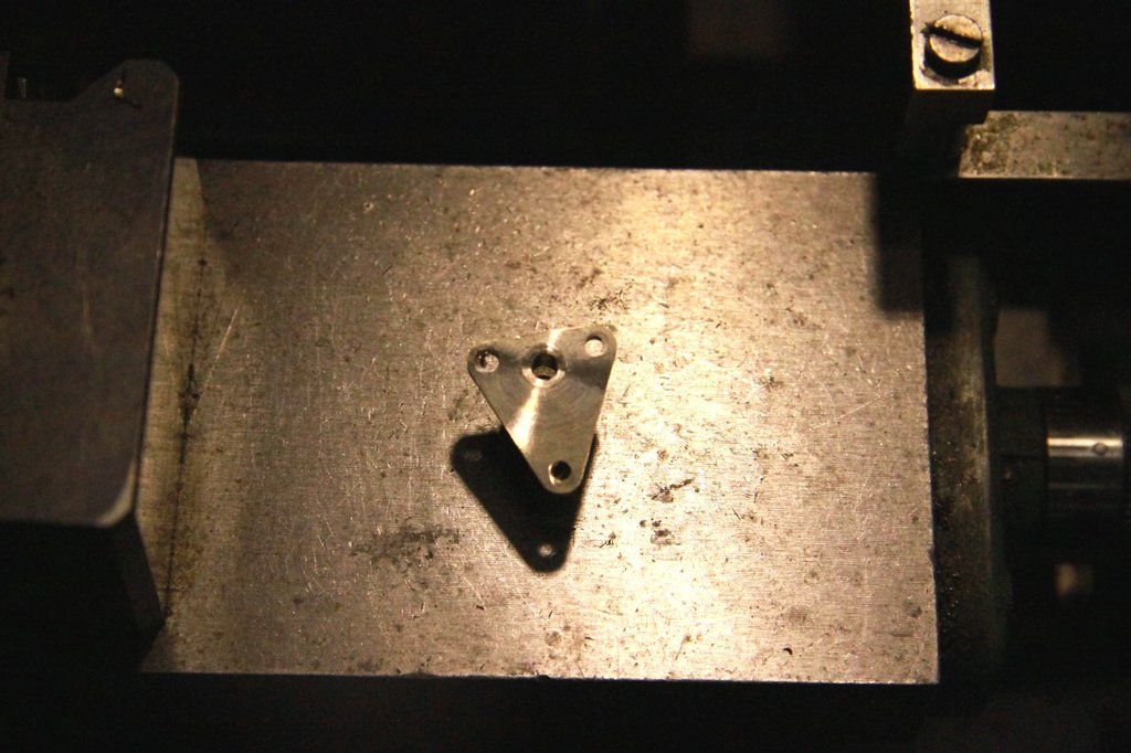 The face has been machined down to the sprue diameter so when the 7/32" dia bore is machined, it will remove the rough bit from the parting-off. Deburr all the holes. The jig for drilling the mounting holes now needs to be modified to hold the casting the other way around. The jig should still be on the mill, and still centred for the mounting hole centres. Move the table to bring the 3/16" hole to zero-zero position. Open the 3/16" hole out to 21/64" / 8.4mm dia x 5/16" - 3/8" deep. Next, with a 9/32" slot drill, slot out the rear of the jig to 0.6" deep to 0.250" back from the zero-zero position as the photos below: 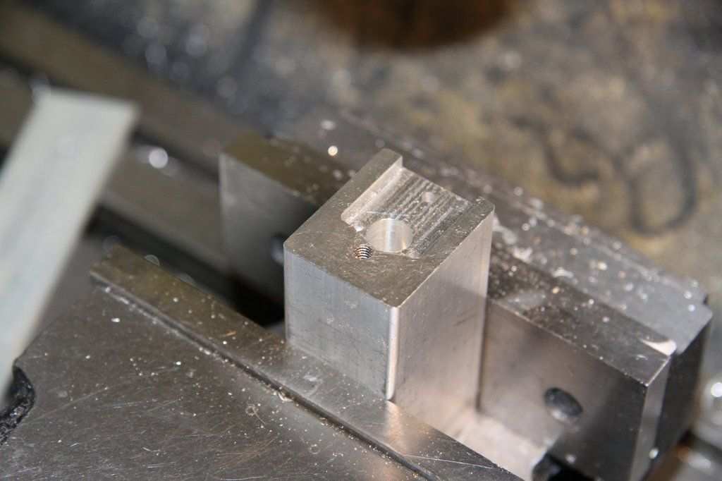 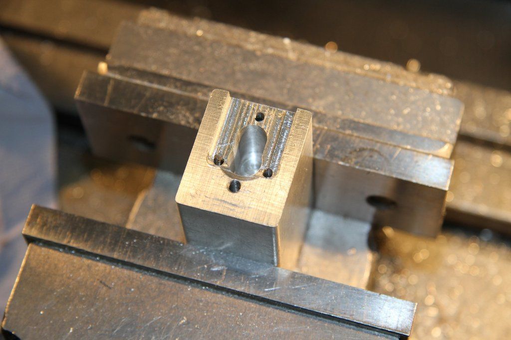 Drill 2mm x 1/2" deep, centred on the mounting hole centres i.e. 0.066" down from where the centre of the 3/16" hole was (zero-zero), and out each side to 0.243". The 3rd mounting hole is 0.487" up from the zero-zero position. Tap these holes 7BA x 1/2" deep approx. Extend the thread on the 7BA fitted bolts made for holding the Spring Pivot Bracket castings, to just leave 1/16" plain fitting diam. Guess who broke a 7BA tap in one of the holes!!! Luckily it was one of the lower holes, not the top one. The casting still sat in the jig using just the 2 bolts instead of 3. 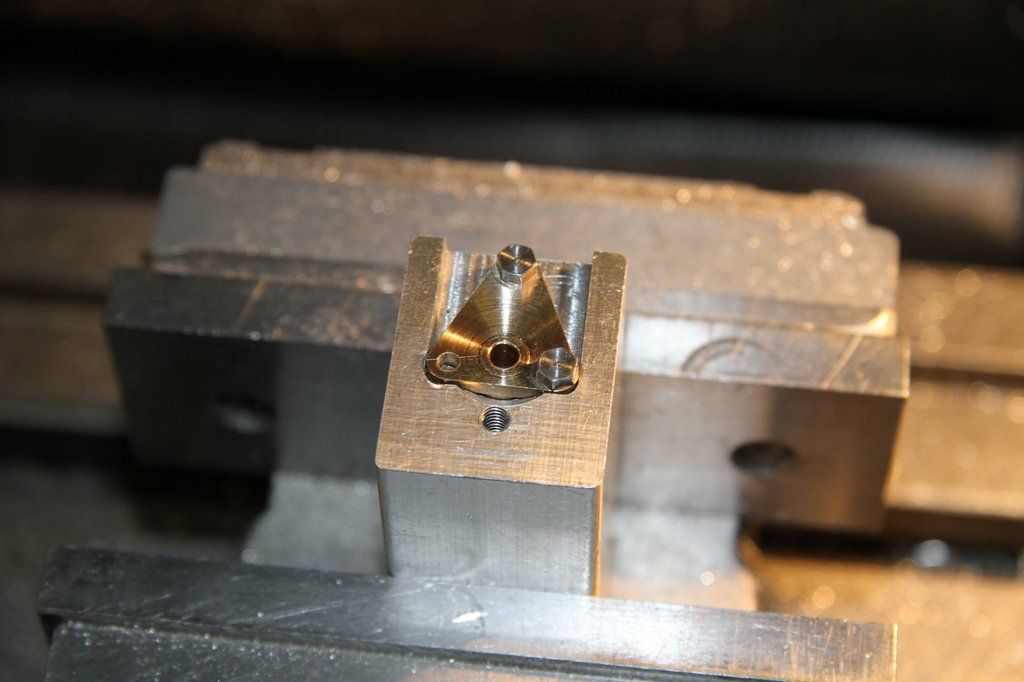 Next - bore out the rear to 0.218" x 0.177" deep. I rough bored it and then finished with a new 7/32" endmill in the tailstock as I have a digital scale fitted to it for accurate drilling depths. The final job is to deburr all over. 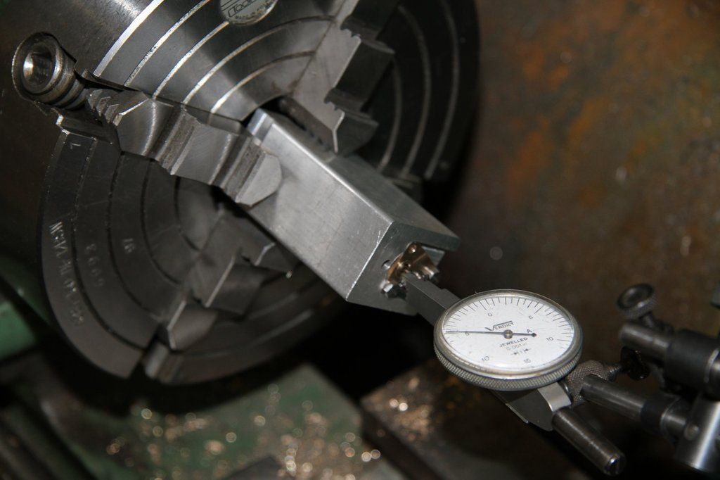 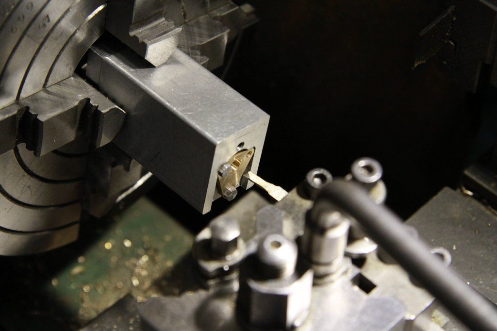 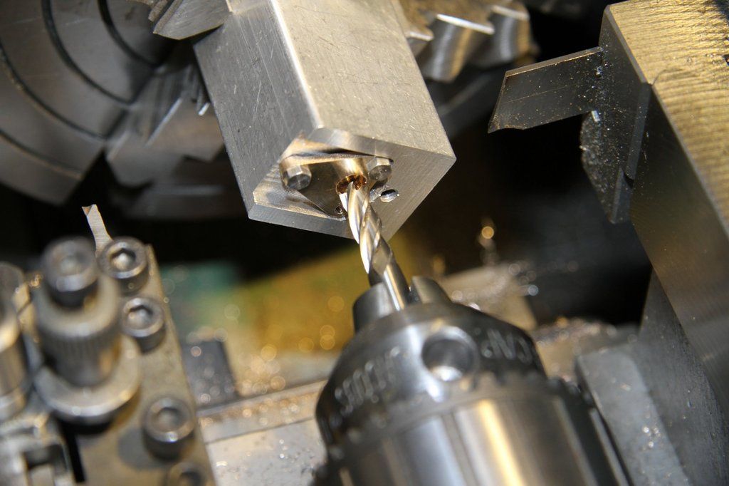 That's the end of machining the castings. The next job is to make the brake hanger pivot pins: The brake hanger pivot pins have a tiny washer between the casting and the split pin. This washer is 0.207" OD x 3.4mm ID x 0.025" thick. As you know, drilling a small hole up a small diameter bar, and then partingoff a washer only 0.25" thick, produces a burr on the ID that makes the hole smaller - a very difficult burr to get rid of with a washer that small. It's actually quite easy. Take the drill that was used to drill the hole in the bar and hold it reversed in the tailstock chuck by holding it on the flutes and as much of the shank as possible. Turn the outside diameter of the bar to the washer OD. Clean up the end of the bar by taking a minute skim with a newly sharpened, 1/16", parting tool. Lock the saddle and zero the topslide micrometer thimble. Bring the shank of the drill forward and enter it into the drilled bore about 0.1". Move the topslide over by the width of the parting tool plus the thickness of the washer. Very gently part off, watching the washer being parted off, and as soon as it stops rotating, stop feeding the parting tool. The washer hole has no burr on the inside, making it smaller, but there is a fine burr on the parted face. That can easily be removed with fine emery. I turned up a little holder to do this by machining the end of a piece of 3/16" dia steel bar down to 0.134" dia x 0.020" long. I parted the bar off, about 3/4" long. I then fitted each washer onto the turned end and rubbed it on 600 grade wet n' dry. The burr was then gone. The washers fitted neatly over the pins which I had previously turned. The holes 0.035" holes for the 1/32" split pins then have to be drilled in the pins. I made up a simple jig to position the pins while drilling the hole. I actually used an old drill jig that had clear surface to re-drill for these pins. I forgot take the photos off the camera. I'll have to do that and add them next time. This was a bit of a marathon this time. I hope it all comes out OK, as I haven't found a way of pre-viewing the content before posting it. |
|
|
|
Post by 92220 on Nov 23, 2016 12:14:18 GMT
Here's a bit more - the castings riveted on to the tender frames:
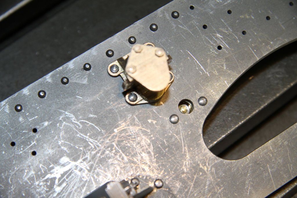

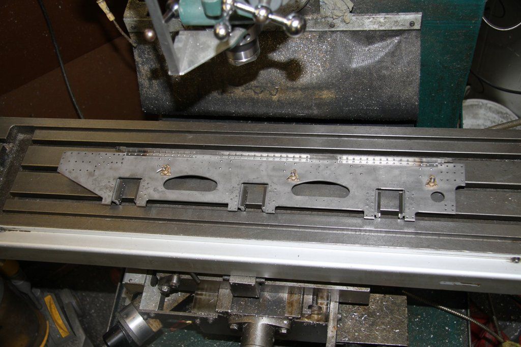
You may be wondering about the rivets holding the axlebox guides on. The fullsize are just hammered into countersinks on the inside of the frames. Mine just have to be tidied up now, before I assemble the frames.
|
|
|
|
Post by Cro on Nov 23, 2016 13:02:13 GMT
Looking great Bob, I'm going to have to look at a new set for my tender at some stage! Thanks for trialling these and doing a great write up.
Adam
|
|
|
|
Post by 92220 on Nov 23, 2016 13:28:44 GMT
My pleasure Adam. I like something to challenge the old grey matter!! One thing I forgot to add to the above post - You will need to make up some special rivet snaps to get around the edges of the castings, due to the small size and the scale shape. This is what I did, using 1/2" mild steel bar: 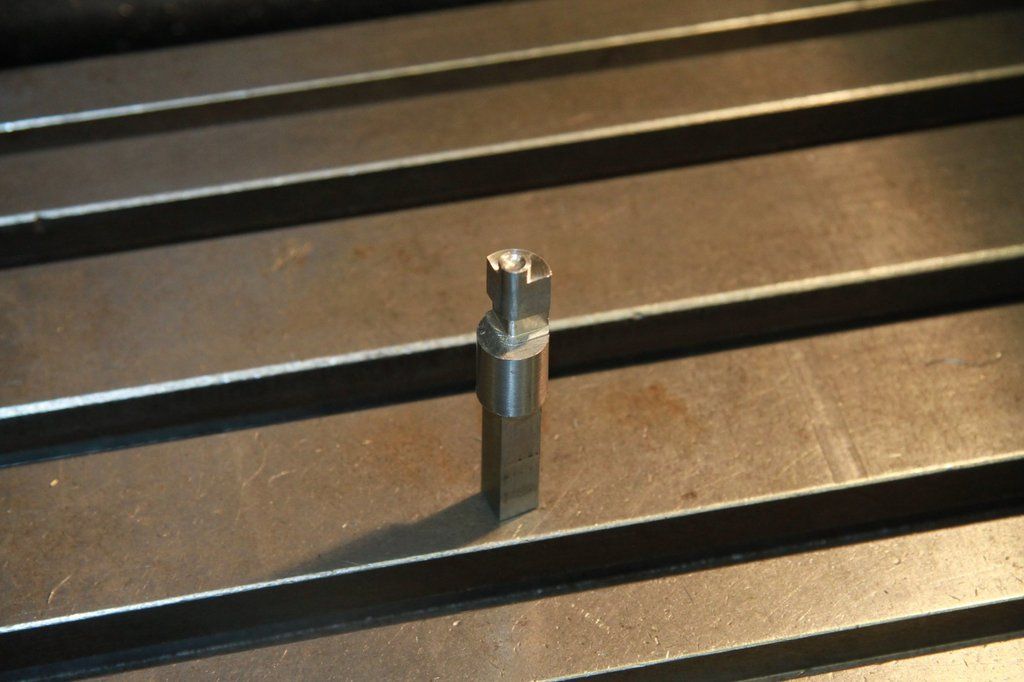 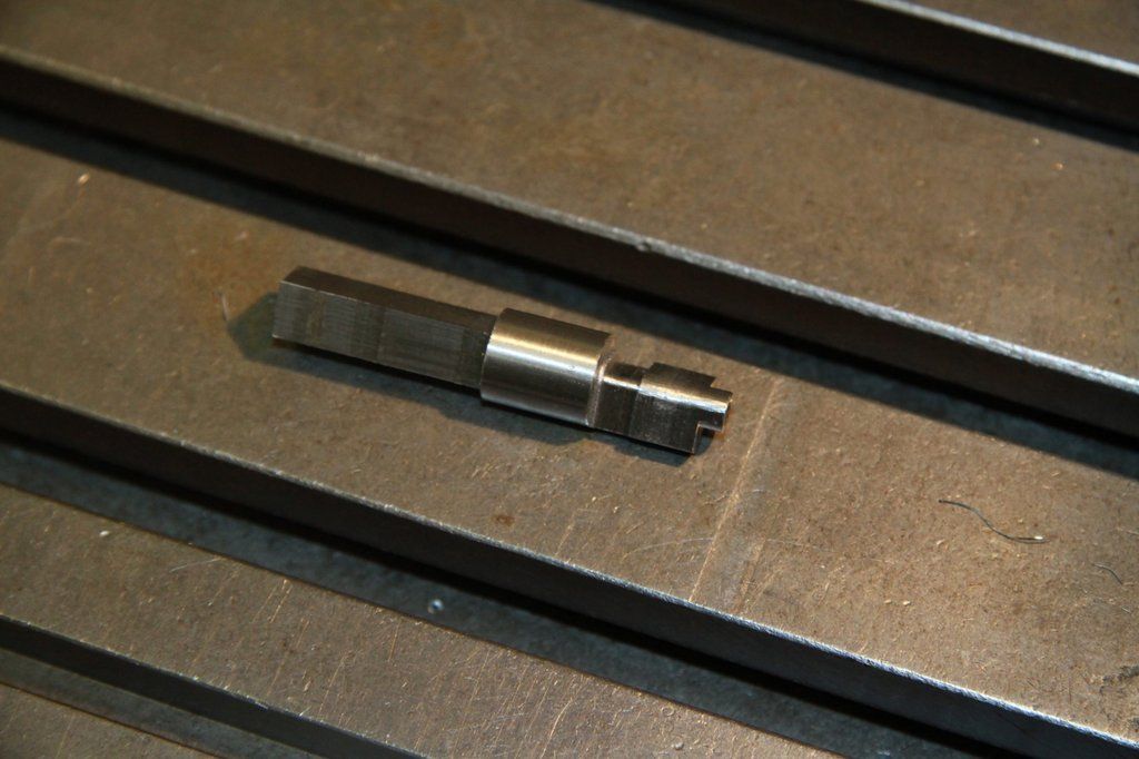 The top was machined at 90 degrees, around the rivet snap, to be able to use it up against the edge of the casting, on either side, just by rotating it the 90 degrees. The actual shape needs to be made while referring to the casting, and making it as close a fit to the shape as practical. I could have made 2 slightly simpler ones but in the end they would have taken longer to make, than the one. The square shank at the bottom is also to allow it to be held at different 90 degree settings. I used a piece of 1" square x 1/8" wall, aluminium tube, about 2 feet long, held horizontal and adjusted vertically by being mounted at about 9/10" from one end to make it non symmetrical, on a piece of M12 studding bolted vertically to the bench. That allowed me to swing it through 360 degrees and use either the long leg or the short leg, and also raise and lower it to set the tender frame plate exactly square to the rivet set. I also found it useful to set it up ready to set the rivet, and lock it all by clamping the frame plate with a toolmakers clamp, where it sat on the 1" ally tube, while the rivet snap was held vertically in the bench vice. That way, I found it much easier to set the rivet without having to juggle everything while riveting! |
|
|
|
Post by Deleted on Nov 23, 2016 13:52:07 GMT
lovely work as always Bob....great craftsmanship sir
Pete
|
|
|
|
Post by 92220 on Dec 18, 2016 17:10:51 GMT
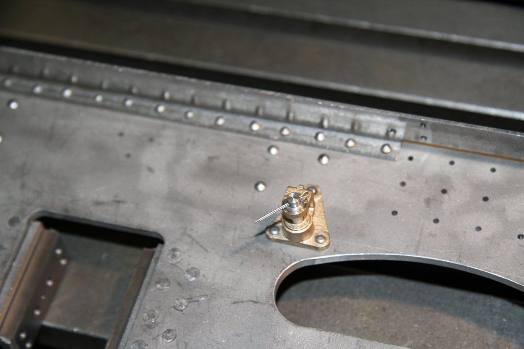
The next job is the brake hanger pins. These are just a simple turning job. The more taxing job is the cross-drilling for the 1/32" splitpin, and the grease nipple in the end. The grease nipple is made from 0.084" a/f brass hex. The head end is turned to just clean up to diameter and 0.05" in length. A grooving tool, 0.025" wide was ground up to cut the groove under the greasing head. After fitting them I did think this was a waste of time because the groove cannot be seen once fitted in place. Anyway, a groove 25 thou wide x 25 thou deep was turned. A No.72 drill was held in the Eclipse Pin Chuck, sticking out just 1/16". I then drilled the end to represent the greasing hole. No centring needed with such a short projection from the pin chuck. The stub, for fitting in the pin, was turned to 0.062" dia using a parting tool. The nipple was parted off with the same tool. These are tiny and easily lost, so I made up a couple of extra ones - just in case!! 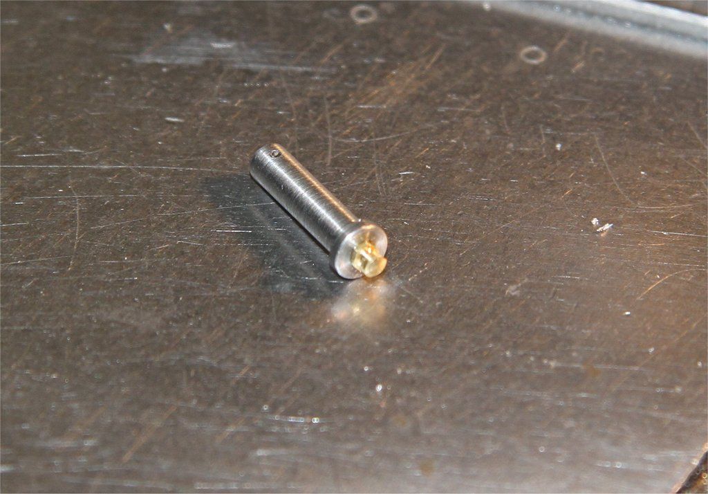   Turning the grease nipples  The next bit to make is a jig to cross-drill the pins for the split pins. I had a piece of mild steel about 3/4" cube that had been used as a jig before, so was square on all faces. I set the vice up on the mill table with the fixed face true to the travel of the table. The block was clamped in the vice and set so that a 6BA tapping hole (2.3mm) could be drilled about 5/32" down from one edge, right through. This was then opened out with a 3.0mm drill, to 0.40" deep, and finally to 3.4mm dia x 0.4" deep. The block was turned through 90 degrees and re-clamped. The axis of the quill was then set to line up with the face of the block with the 3.4mm hole in it. A No.1 centre drill was set up in the drill chuck and a centre was drilled 0.30" from the face, then a No.65 (0.90mm) hole was drilled through the 3.4mm hole and into the other side for a short distance. The block was again turned through 90 degrees to bring the 6BA tapping hole upwards. A 2.3mm drill was put in the hole and then gripped in the chuck to get the hole lined up. The drill was swapped for a HSS 6BA taper tap, and with the spindle speed set to minimum, the 2.3mm hole was tapped out, using a spot of RDT lubricant.  Next, I turned up a dummy pin on the end of a piece of 1/4" mild steel bar. I worked out the distance the splitpin hole had to be, from the underside of the pin head, taking into account the 25 thou washer and 0.010" clearance between the washer and the pin. I made up a collar to fit over the pin, to a length that I calculated could be used to locate the pin at the right distance from the No.65 drill hole. The drill was then put in the hole in the drill jig and then clamped in the drill chuck. The vice was then clamped and the drill checked to see that it would enter the hole without deflection. The collar was then put on the pin which was then put in the jig and pushed in tight. The No.65 hole was then cross-drilled in the pin. I then checked that it would fit in the brake hanger bracket with the 25 thou washer and split pin. As it turned out, I had miscalculated and the pin hole was right up against the washer with no clearance to ease fitting, so I made up another collar, 10 thou longer. The collar was fitted over the pin and the pin again put into the drill jig. With the dummy pin pushed in tight, the 6BA screw was screwed in until it just touched the end of the pin. The screw was then locked in place with a nut, so that it acted as a stop for the pins to be drilled all at exactly the same distance from the ends. I've used this method of making drill jigs for all the pins, used on the loco, that have split pin locking. 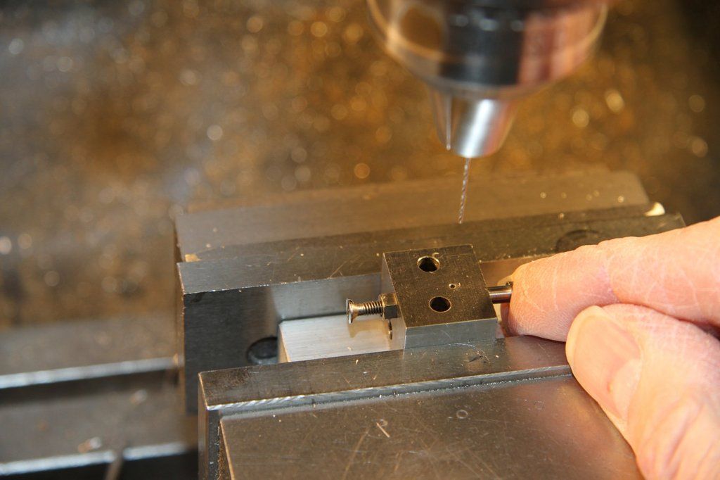 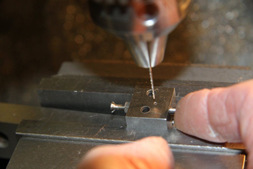 The finished pin in the Brake Hanger Bracket, before riveting to the frames. 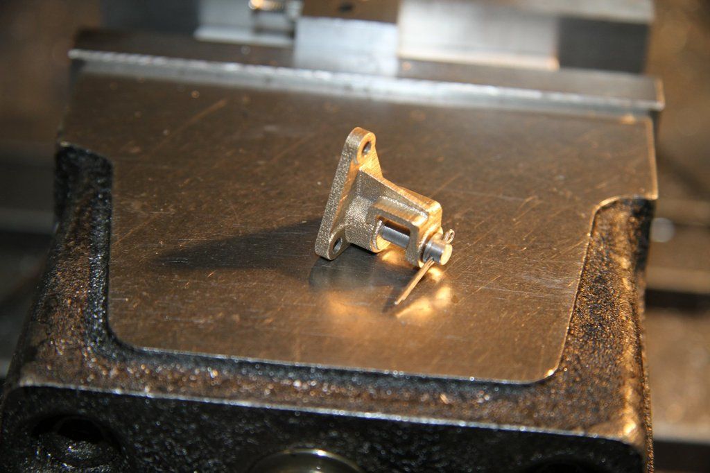 |
|
|
|
Post by 92220 on Dec 18, 2016 18:26:06 GMT
|
|


