|
|
Post by Roger on Dec 23, 2016 19:04:49 GMT
.... but all of these methods assume that there's no runout, and that's not the case. I would suggest that a wobbler used on both sides is going to be more accurate than any of these methods. It the diameter is big, then it's not so important. I doubt if they would be adequate to drill that 0.5mm hole through the 0.8mm shaft that I needed for the water gauge.
|
|
|
|
Post by 92220 on Dec 24, 2016 8:54:38 GMT
Roger is right about the runout. You will be VERY lucky to get a chuck that runs dead true. Almost impossible. Even my brand new ER collets have a 0.0015" TIR runout! When setting up with the ciggy paper I always use a collet in the spindle taper. When I first set it up and checked with the DTI the runout was 0.0002". I keep the collet and setup pin in a box on it's own, to make sure that it stays accurate. It always pays to make sure the spindle taper is clean too, with no tiny bits of swarf dust in it. I did have a Jacobs chuck that ran true within 0.002" TIR but that has since changed to 0.005", and neither being good enough to use for setup anyway.
|
|
|
|
Post by 92220 on Dec 24, 2016 9:25:39 GMT
The postman has just delivered my first 0.8mm PCB drills. Now to see how I get on with them. It will be interesting to see if they will stand being used in the quill of the mill, or whether I have to use the sensitive drilling machine. I have no idea what speed to use! The mill runs at 3000 revs max for a few minutes before the bearings start to get warm, but the sensitive drill can run at up to 8000 RPM all day. Any advice Roger?
|
|
|
|
Post by Roger on Dec 24, 2016 9:39:24 GMT
The postman has just delivered my first 0.8mm PCB drills. Now to see how I get on with them. It will be interesting to see if they will stand being used in the quill of the mill, or whether I have to use the sensitive drilling machine. I have no idea what speed to use! The mill runs at 3000 revs max for a few minutes before the bearings start to get warm, but the sensitive drill can run at up to 8000 RPM all day. Any advice Roger? Personally I'd use them in the quill with the handwheel to feed it in. You won't feel anything, so just use your eyes and ears to see what's going on. You don't need a really high speed, 1500RPM is fine, but you can go more if you like. You can go as slow as you like with any machining operation, it just takes longer. Watch the initial touchdown and let it just settle down and create a centred hole in the right position. Don't try to generate a spiral of swarf, be content to turn the metal into dust. Advance the drill very slowly indeed, treat it as being really fragile. As a caveat to this, it's worth noting that these are not as fragile as the impression I'm giving. They certainly can produce curly swarf, but is it worth the risk of breaking it and leaving the drill in the hole? If you turn the metal to dust, if the drill does break, you'll almost certainly get it out. The is the same method I would use for drilling out a broken tap. Giving it time to turn the metal to dust means it stays centred. As a party piece, why not drill a hole through a ball bearing? Out of interest, that drill would be used at about 60,000RPM on a PCB drilling machine, and it would be drilling through a stack of boards about 4mm thick at about three holes per second. It looks like it's punching them! |
|
|
|
Post by vulcanbomber on Dec 24, 2016 9:58:15 GMT
We did some 0.4mm holes at work a few weeks back. They suggested 76000 RPM for that drill bit.
|
|
|
|
Post by 92220 on Dec 24, 2016 10:02:26 GMT
Thanks for the advice Roger. I have no immediate use for the drills, but as they are so cheap (£6.24 for 5 inc. postage) I am happy to try them on different bits of scrap and risk breakages. I just needed some advice as a starter, and thanks for that. Your idea of drilling a ball bearing sounds brill ! I shall definitely try that ! Shan't be in the workshop for a few days though. Gaffer might put me on the naughty step!
Happy Christmas to you and everyone on here.
Bob
|
|
|
|
Post by Roger on Dec 24, 2016 10:49:16 GMT
We did some 0.4mm holes at work a few weeks back. They suggested 76000 RPM for that drill bit. Hi Dave, That's probably about right for production drilling in hard materials. You'd probably be looking at 150,000RPM for that on a PCB. They use 250,000RPM for the small drills ie 0.2mm and below. The only reason for the astronomic RPM if to drill as many holes as possible in the shortest time. In PCB manufacture, there are often thousands of holes on a board, so it's vital to crack on with it to keep the cost down. If you're only drilling a few holes, it's not as important. You do have to remember that these drills are optimised for drilling glass reinforced materials though, so the edges are very fine. That means they are prone to chipping of you get heavy handed. |
|
|
|
Post by 92220 on Dec 24, 2016 11:53:50 GMT
Also, the higher the RPM, the stiffer the drill and so less likely to wander off centre in deep holes, though I don't suppose that is a problem with PCBs.
|
|
|
|
Post by Roger on Dec 24, 2016 12:30:07 GMT
Also, the higher the RPM, the stiffer the drill and so less likely to wander off centre in deep holes, though I don't suppose that is a problem with PCBs. I'm not sure that's strictly true. If you go beyond the whirling speed of the drill, anything can happen. Wander is a problem with PCBs, especially if you drill four high in a stack. That's becoming less common these days because the trend is towards smaller holes to get the component density higher, and that means you can't have the full 10mm flute length you get with bigger drills. This sort of thing isn't really considered by many PCB designers who don't know how boards are made in the real world. As soon as you put one hole that restricts the number you can drill in a stack, you've reduced the productivity without even realising it. I try to avoid any holes less than 0.7mm on my designs so that this isn't an issue. High aspect ratio holes also cause issues with getting the chemicals down the holes to plate them through. All PCB stacks are drilled with an entry material to assist accurate penetration without skating to one side. It's usually a thick hard Aluminium foil, although they used to use a Phenolic years ago. There's an awful lot to get to get to grips with PCB drilling, it's not as simple as you might think. |
|
|
|
Post by keith1500 on Dec 25, 2016 8:10:23 GMT
Personally I hate drilling small holes. I get the impression that if I use a high speed and so much as dither for one moment the drill no longer cuts, gets hot, expands, grabs and consequently breaks! So I tend to use lower speeds. Perhaps it is my technique that's wrong or is it the quality of the drill bit? These PCB drills sound quite good?
|
|
|
|
Post by Roger on Dec 25, 2016 10:16:45 GMT
Personally I hate drilling small holes. I get the impression that if I use a high speed and so much as dither for one moment the drill no longer cuts, gets hot, expands, grabs and consequently breaks! So I tend to use lower speeds. Perhaps it is my technique that's wrong or is it the quality of the drill bit? These PCB drills sound quite good? No, you're not wrong, an unhealthy obsession with high spindle speeds is the root of many problems with small hole drilling. I'm also not a fan of those 'sensitive drilling attachments', there's no need to 'feel' anything to drill small holes. I use slower speeds and feed using a handwheel. HSS can be kept cutting (I use cutting oil too), but I find that carbide is best used by slowly letting it turn the metal to powder. Take plenty of time and feed very slowly. With carbide you can use a much higher RPM if you want, but you don't have to, it just takes longer. The main thing is that it's hard and sharp enough to cut almost anything. So drilling a hole in Stainless or anything that's hard is all done the same way. I don't find cutting oil has much bearing on the outcome if you use carbide drills. |
|
|
|
Post by 92220 on Dec 26, 2016 9:16:37 GMT
Hi Roger.
Those RPM numbers you quote are what I was referring to. They, to me, are the higher end of the rev range when I am used to using no more than 8000 RPM. I Know..... I'm just a 'slow coach'!! Must admit though, I never realised that you had to use those high numbers for PCBs, after all it's only like Tufnol coated in copper foil - not that I know anything about their machining qualities!!
Bob
|
|
|
|
Post by simplyloco on Dec 26, 2016 9:37:06 GMT
Hi Roger. Those RPM numbers you quote are what I was referring to. They, to me, are the higher end of the rev range when I am used to using no more than 8000 RPM. I Know..... I'm just a 'slow coach'!! Must admit though, I never realised that you had to use those high numbers for PCBs, after all it's only like Tufnol coated in copper foil - not that I know anything about their machining qualities!! Bob I've made replacement gears out f the stuff, and if I remember correctly it was highly abrasive and inhaling the dust was not healthy! BTW for those who may not be familiar with Proxxon tools I've been using their BF40 Mill/Drill for many years now. Fantastic piece of kit which has a powerful motor giving infinitely controllable spindle speed of up to 6000 rpm. Not cheap, but in this case you get what you pay for! John www.proxxon.com/en/micromot/20165.php?list |
|
|
|
Post by Roger on Dec 26, 2016 10:08:39 GMT
Hi Roger. Those RPM numbers you quote are what I was referring to. They, to me, are the higher end of the rev range when I am used to using no more than 8000 RPM. I Know..... I'm just a 'slow coach'!! Must admit though, I never realised that you had to use those high numbers for PCBs, after all it's only like Tufnol coated in copper foil - not that I know anything about their machining qualities!! Bob Hi Bob, You can use 8000 RPM with carbide PCB drills if you want, but you don't have to. I might set up my high speed spindle to do lots of holes, but for most purposes I use the main spindle and never top speed with that. I'm guessing, but I doubt if I ever exceed 5000RPM because it's just thrashing the spindle for no good reason. Take a look at this market leader in Air Bearing Spindles and you'll see what industry is currently using. The 370,000RPM spindles are used for 0.1mm holes to get more holes per second. You can drill a 0.1mm hole at 1000RPM if you want, but in production it would take forever. Small hole sizes seriously restricts the thickness of the boards you can drill. If you take a look at this PCB drill/router manufacturer you can see how the drills are all the same length overall, but there's a necked down section which progressively gets shorter as the drill diameter gets smaller. The smallest of holes tend to be reserved for things like the flexible circuits that connect print heads and that sort of thing so the circuits are thin. The highest speed spindles are used solely for drilling, but as the speed drops, Air Bearing Spindles can provide enough side load (up to 10kg) so they can be used for routing. That's why there are still slow speed spindles on offer (80,000RPM) because they are more flexible and can still drill the smallest holes, albeit slowly. My company specialised in the repair of PCB drilling and routing spindles, and it becomes a nightmare when you breach the 125,000RPM barrier where it becomes extremely difficult to achieve good enough balance. Fortunately, I sold the company before we had to invest in the super precision machines and measuring equipment necessary to deal with the modern spindles. |
|
|
|
Post by 92220 on Jan 2, 2017 9:32:08 GMT
|
|
|
|
Post by 92220 on Jan 2, 2017 9:40:28 GMT
The first photo of the tender frames should have been the last one. That's as far as I had got when I took the photos. Not a lot has happened over the holiday but I'm working on the packing. On the fullsize B1G tender, the frames packing is, believe it or not, wood! However, I'm not prepared to risk it rotting over time so I am deviating from scale and making the packing in mild steel. It's not seen anyway.
|
|
|
|
Post by Deleted on Jan 2, 2017 11:22:27 GMT
Hi bob Tender's looking great, as a point of interest, Gresley 8 wheeled tenders also used wood for packing for between the vacuum reservoir and undersides of the dragbox. I used solid oak, the same as used for the soleplate (and later cab) flooring. I don't think that it's going to rot, well at least not in my lifetime..  cheers Pete |
|
|
|
Post by 92220 on Feb 27, 2017 13:58:48 GMT
It's been a while since I added anything to the thread. I've been drawing up, and making the axleboxes. The drawing up has been a bit problematical as the internals are obviously different to the fullsize boxes. I have 2 ball bearings in each, and had to source fine-section bearings to fit in. I then had to work out how to fit them inside and how to make any adjustments to keep the boxes against the guides. The outer boxes will have minimum clearance to retain a rigid wheelbase, with the middle axle floating to allow for running around tight curves. I forgot to take any photos of the early stages of machining the axleboxes but they started off as just simple blocks of mild steel with 'ears' sticking out each side, at the back, for the rear faces that run on the backs of the axlebox guides. The slight tool marks on the sliding faces will actually work fine as oil retaining 'reservoirs' for lubrication.  This is the box held in a jig to hold them all in the same position under the quill to drill the bearing hole:  This is boring the bearing holes right through to the inside diameter of the shoulder to locate the bearings. If anyone is after a good boring head, this is the one to go for. It's an old Archer head and the graduations are in thous on diameter so no thinking about the adjustment. One graduation is 1 thou on diameter, and it will work comfortably to this close. The bore can then subsequently be used to set the axlebox in the lathe, for final boring.  The next job was to bore the back face, in the lathe, for the bearing locking collar. The first problem was that the axlebox wouldn't sit flat on the face of the 4 jaw because of the centre hole. A piece of 1/8" plate was machined to just fit inside the jaws, and to bridge the centre hole:  I nearly forgot the centre hole in the plate, for the boring tool to go through: 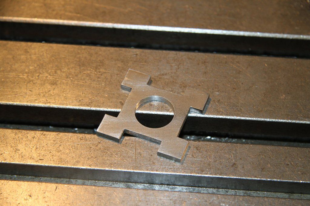 I used a couple of pieces of copper plate, bent at right angles, to prevent chuck jaw marks on the boxes. 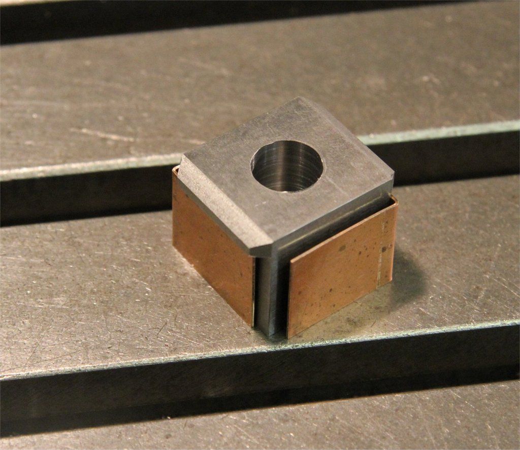 Once set up and centred in the 4 jaw, within 0.001" TIR, the box was bored to 0.709"/0.710"" for the 18mm bearings to be a push fit. 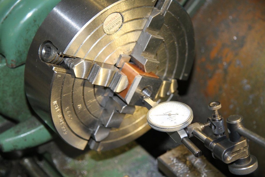 Once the boxes were bored to size, they were set back up in the jig and the bore centred under the quill. The DRO was then set up to drill 6 holes, 1.40mm tapping size for 10BA, on a 0.828" PCD. As each box was drilled the chuck was replaced with the tapping head, and the holes tapped on the same centre settings. The next job was to make little cut-outs, in the front of the bore, so that the bearings could be easily removed from the boxes. The front face of the boxes were then radiused. The axlebox cover castings were then drilled for the fixing studs. These were used to spot through to the axlebox and then drilled and tapped 12BA for the fixing studs. Studs were made by parting off the ends of 12BA x 1/2" steel screws. They were then fixed in the axleboxes with loctite. 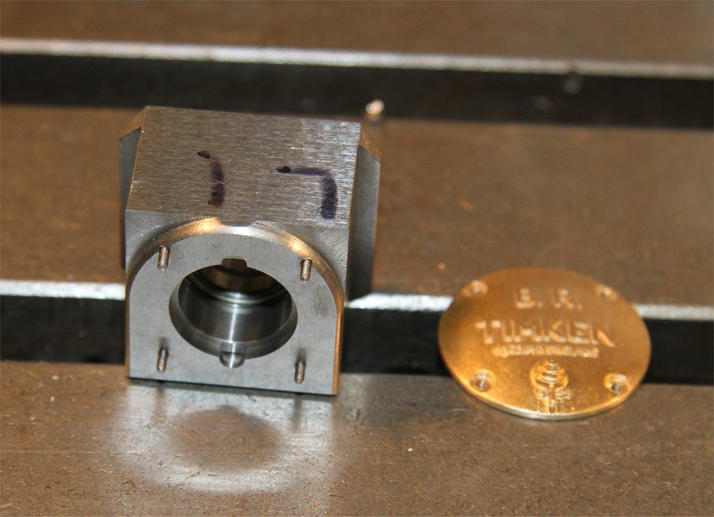 The backs of the cover castings needed to be skimmed flat. They couldn't be held by any means without damaging them. I came up with the idea of Aralditing a stub on the back face, to hold in the chuck while lightly skimming the rear face. I made up a jig to hold the castings and a piece of 1/2" dia brass bar, concentric with each other, while the Rapid Araldite cured. Lucky for me, the OD of the castings were all within 2 thou of each other! 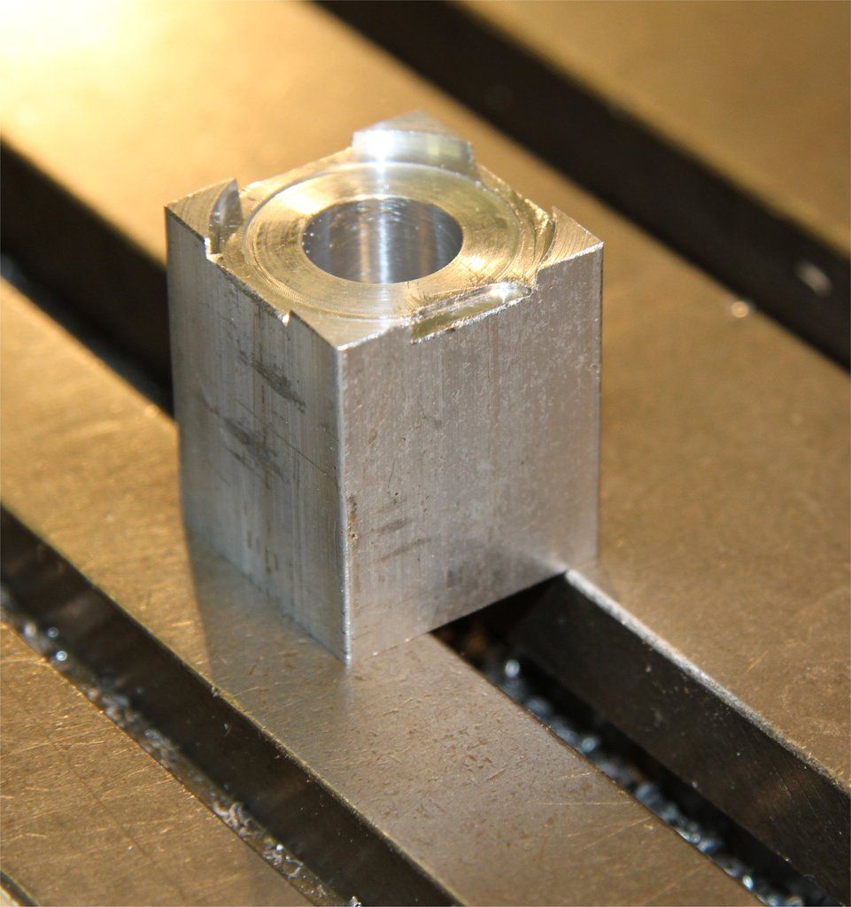 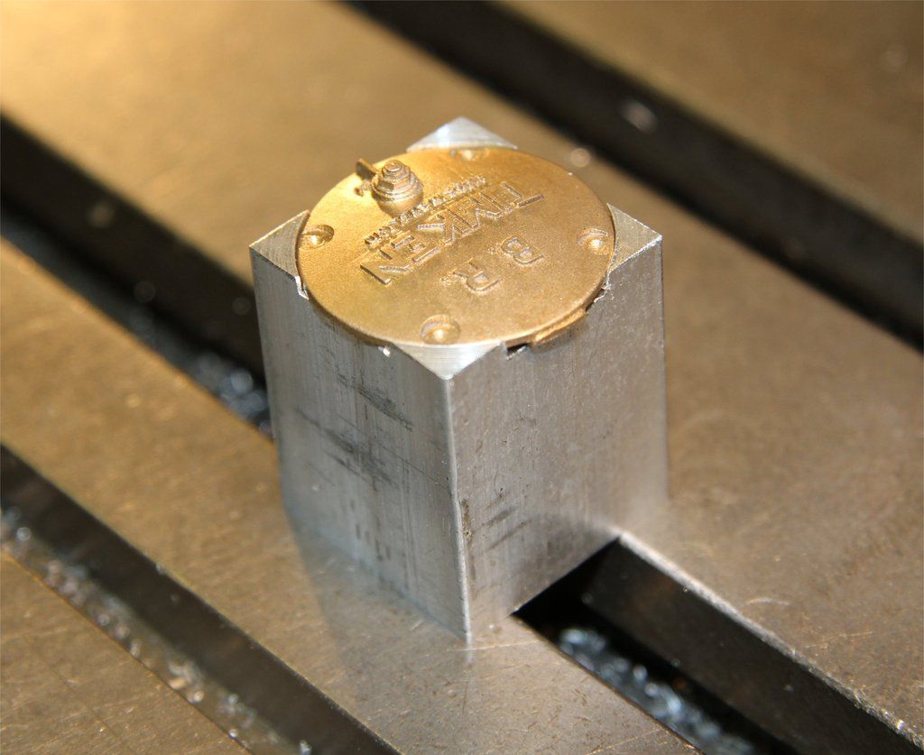 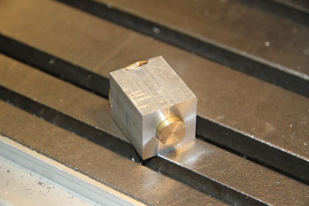 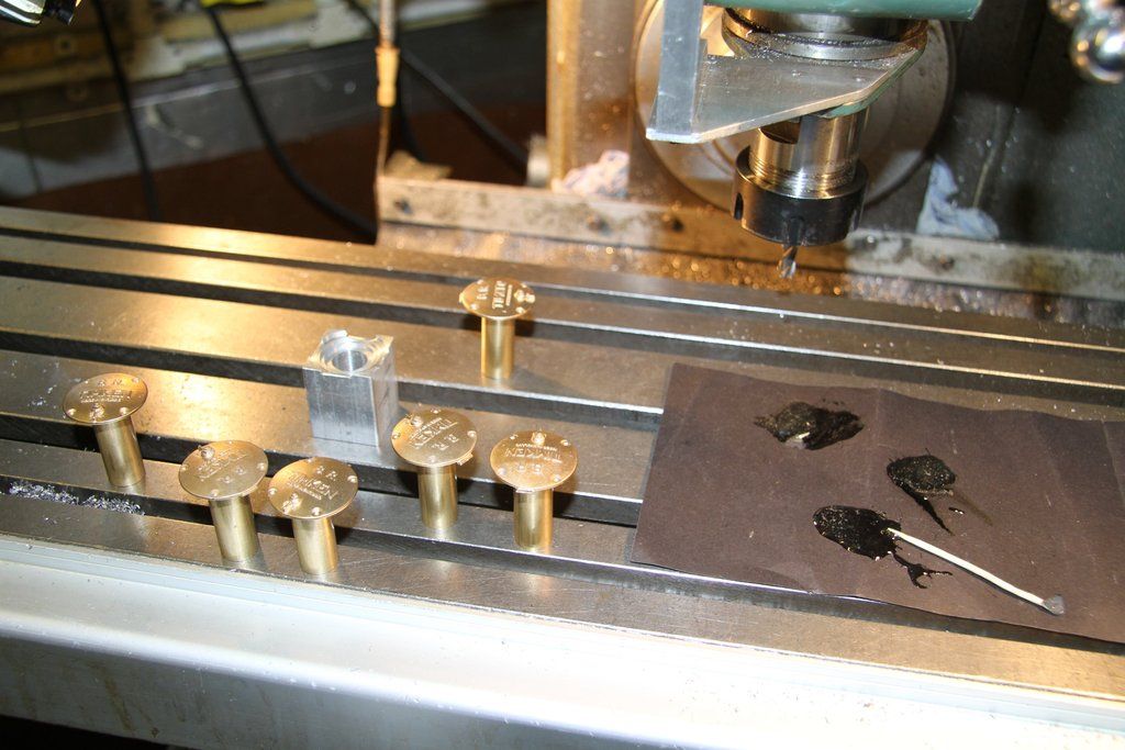 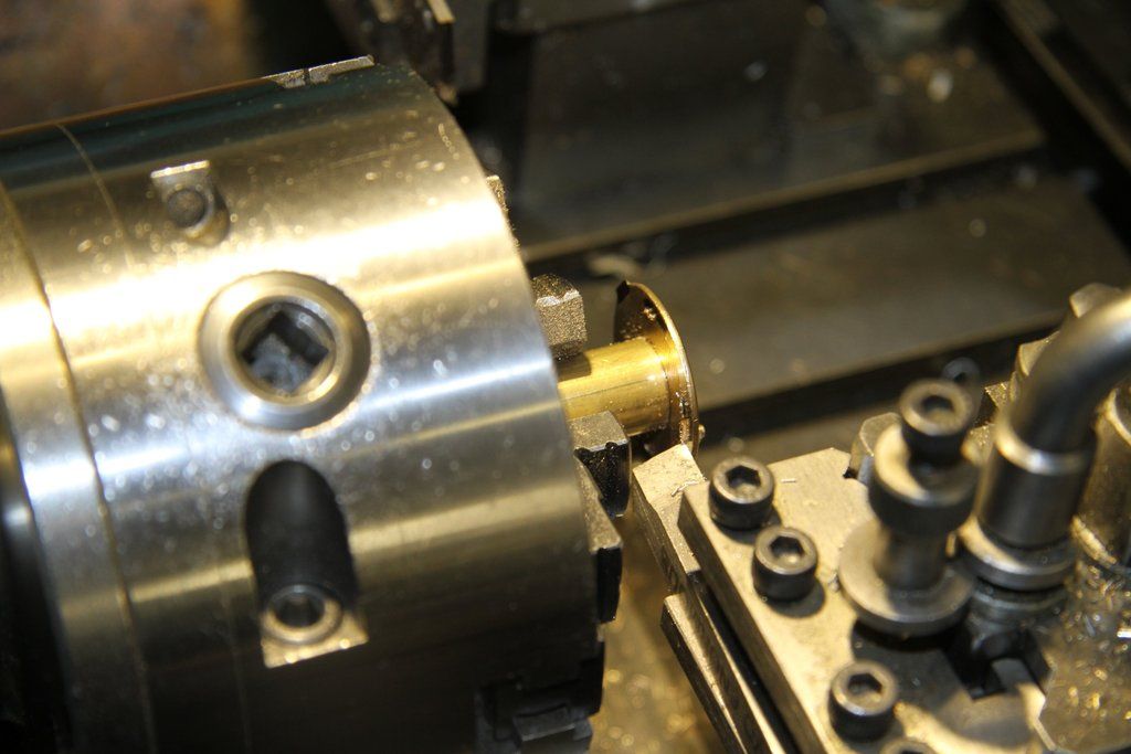 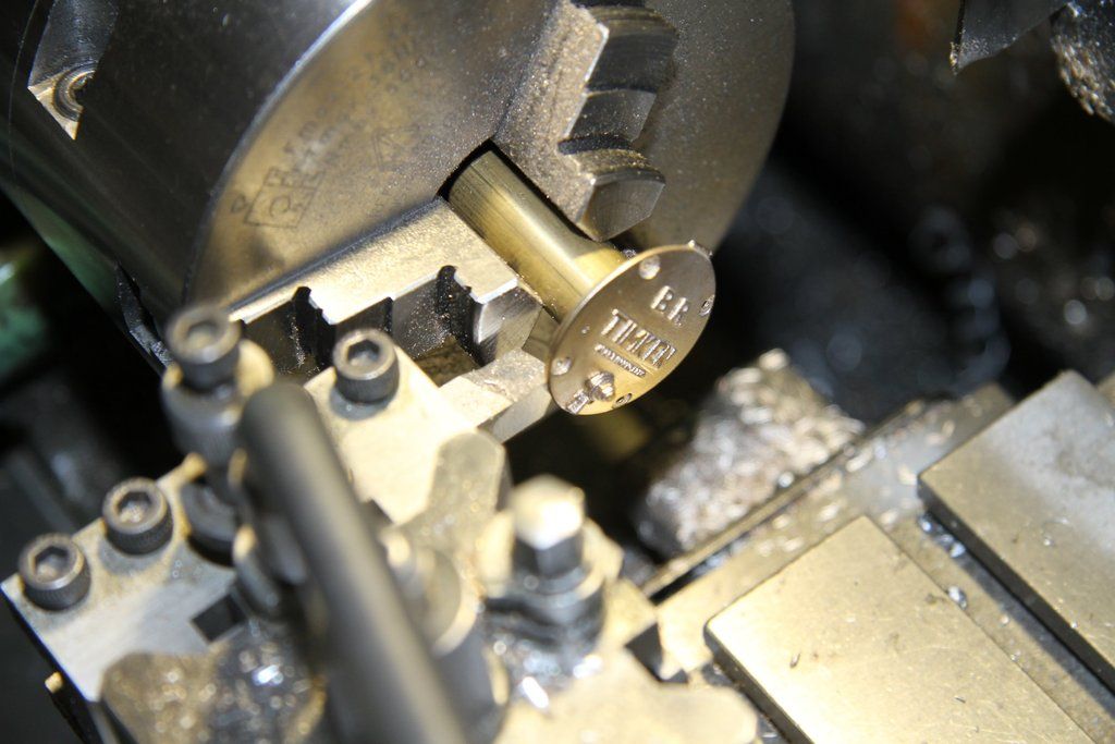 A finished axlebox: 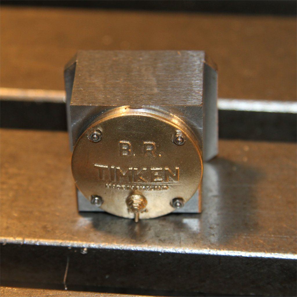 The axleboxes in the frames: 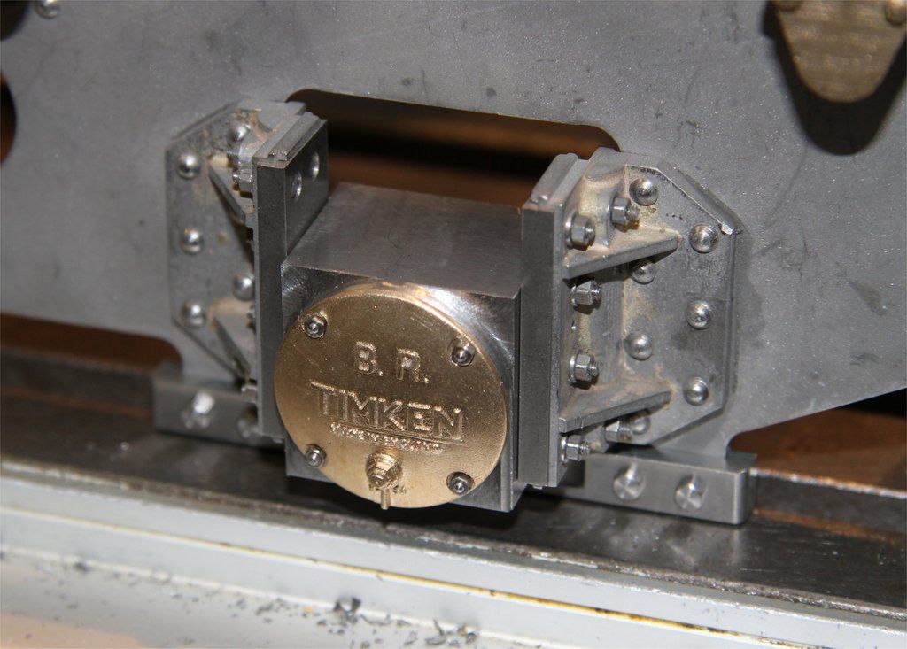 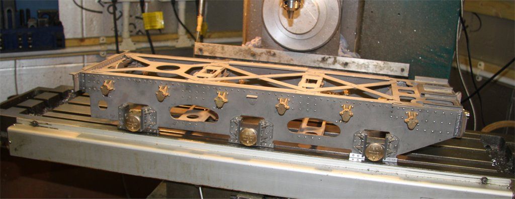 The next job is machining the axles, but that has to wait until the metal arrives - hopefully in the next few days. |
|
|
|
Post by noggin on Feb 27, 2017 19:22:06 GMT
Really nice workmanship,Look forward to this thread,can i ask how you broke the aradite seal,I would be worried that that may of damaged the covers as well, Thanks Garry
|
|
|
|
Post by 92220 on Feb 27, 2017 19:35:49 GMT
Hi Garry. Thanks for that kind comment. I used a parting tool to cut down to about 1/4" dia behind the cover. The araldite hadn't fully hardened and with careful persuasion, the cover parted from the brass bar, leaving a clean cast surface. I was prepared to part it off fully and be left with a shallow boss on the back but that wasn't necessary. The boss would have fitted inside the hole in the axlebox, if I had had to fully part off. This is why I used Rapid Araldite. It hardens so far as to provide a very strong grip in shear after about an hour, but it takes a full 24 hours to go hard. After an hour the grip is still hasn't reached maximum in tension so was quite easy to separate the two bits. I glued the covers on and left them for about an hour before skimming the backs and separating them from the bits of brass bar.
Bob.
|
|


