4303
Active Member

Posts: 44 
|
Post by 4303 on Oct 11, 2016 14:11:49 GMT
I've revived a pair of projects that have 'lain fallow' for several years but are now back on the bench. My query is regarding the compensating lever which links the leading springs to the sliding 'plug' in the front stay and pivots beneath the cylinder blocks. Is there a spring within the sliding 'plug' to provide resistance or is it just the short spring above each axlebox which does the work? There is nothing shown on the Shortland drawings (the later back-draughted set which replaces the original pencil ones) but the GWR works drawing (98682, Feb 1934) shows what looks like three rings within the sliding 'plug' stay. Alan Crossfield rebuilt his large prairie without any compensating arrangement and in an email to me some while ago said that the running was not affected. The drawback though is that the 'extra' spring hanger would be right where the front brake hanger bracket is attached to the frames. Could someone clarify please.
|
|
|
|
Post by Rex Hanman on Oct 11, 2016 18:45:10 GMT
I have built mine without anything other than a sliding fit. I believe I read somewhere that the full size had leather rings to act as dampers and that it took several tons force to move them. Not necessary in our sizes I suspect!
|
|
uuu
Elder Statesman
 your message here...
Posts: 2,807
|
Post by uuu on Oct 11, 2016 19:52:43 GMT
Not having a copy of GWR drawing 98682 to hand, could someone with a copy please say what we're talking about?
Wilf
|
|
|
|
Post by Rex Hanman on Oct 12, 2016 22:50:00 GMT
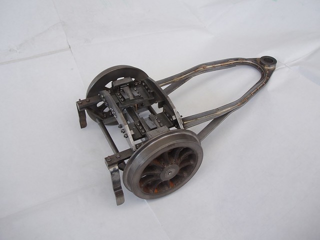
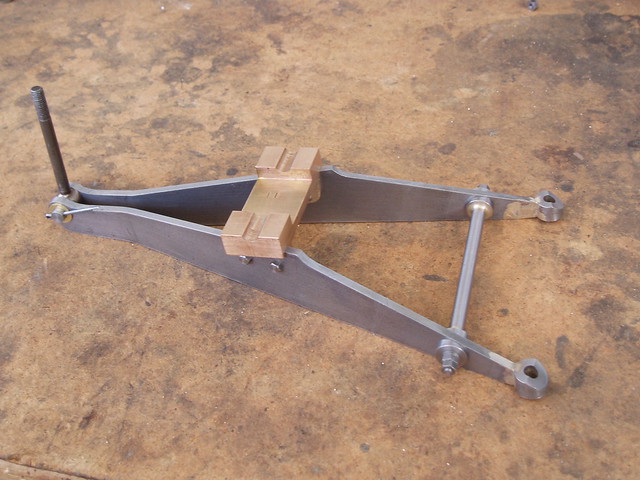
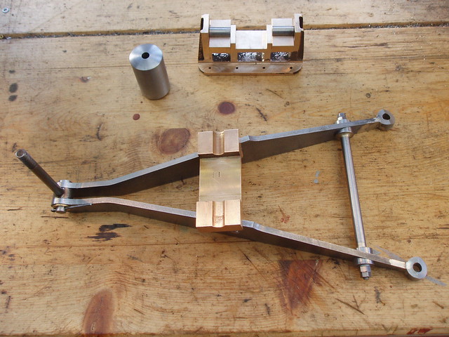
On a lot of GWR engines the front end of the leaf springs of the leading driving wheels are not suported by traditional spring hangers. Instead they are joined to a Y shaped beam (or sometimes T shaped) that is pivoted near its centre. The other end goes to a "piston" like arrangement in the stretcher above the centre of the front pony truck. Others more knowledgeable may explain the workings in detail but it's all to do with the suspension and equalising the weight between the pony truck and the driving wheels. Here in this upside down shot you can see the equalising beam (the red bit) and the end of the leaf spring. The casting at the other end sits on top of the pony truck. (here as yet not fully machined). 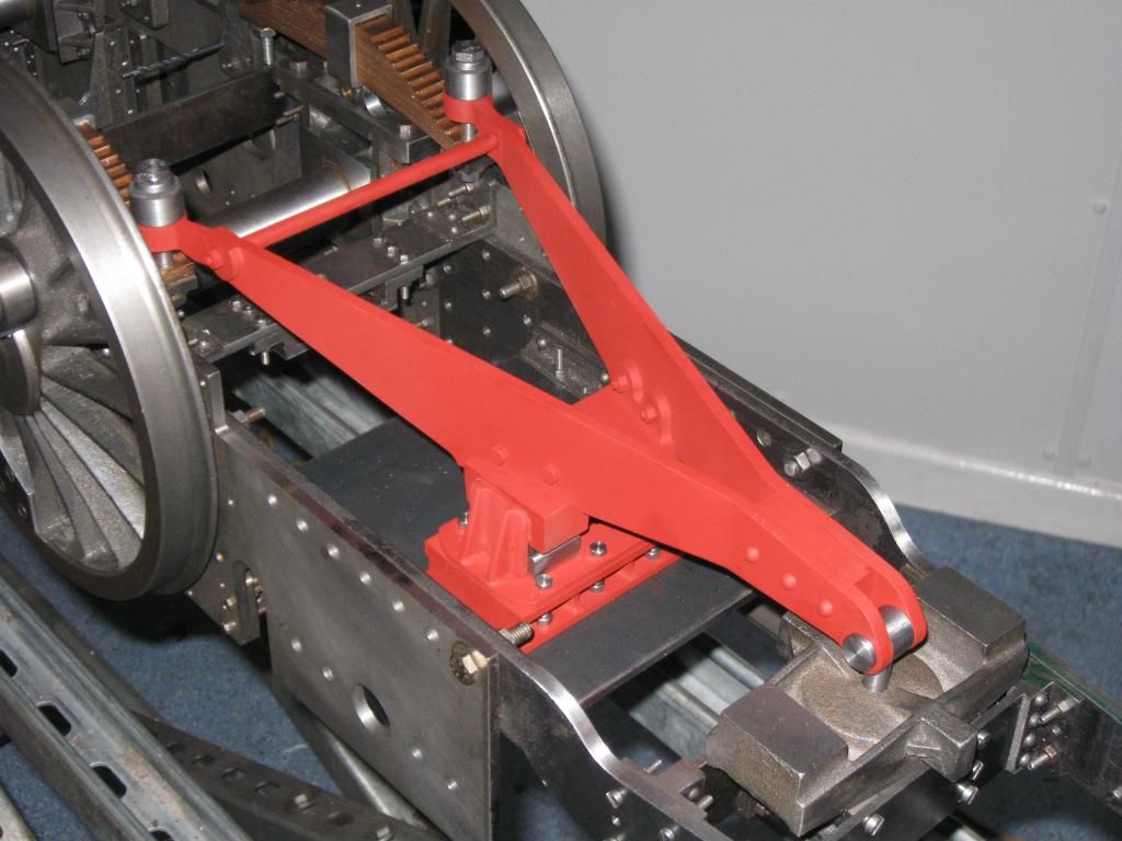 The same casting can be seen here, this time the other way up, with the pont truck underneath it. The end of the "piston" is domed and sits in the depression in the centre of the casting. A pin comes up through the centre hole from the end of the Y and joins the "piston" to the beam. The pony truch pivots around the end of the "piston". As I understand it, if the pony truck moves upwards the open end of the Y moves downwards equalising the weight, but I stand to be corrected! 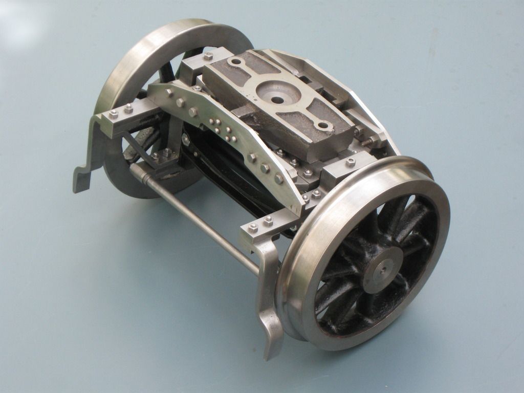 Hope that helped, please ask if it didn't! Edit: Please don't ask about the drill bit visible in the top left of the first picture...that would take a lot more explaining!  |
|
uuu
Elder Statesman
your message here...
Posts: 2,807
|
Post by uuu on Oct 13, 2016 6:21:23 GMT
A picture tells a thousand words. Thank you.
Wilf
|
|
|
|
Post by Laurie_B on Sept 16, 2017 10:18:33 GMT
|
|
|
|
Post by Rex Hanman on Sept 16, 2017 14:25:08 GMT
Thanks for the pictures Laurie B, I hope to restore mine at some point but it will be a lengthy job.  |
|