abby
Statesman

Posts: 925
|
Post by abby on Jan 17, 2017 17:37:10 GMT
I would guess that given the nature of model engineering , most contributing members are within quite a narrow age group and I suspect have had responsible careers in a branch of the engineering industry. There will be exceptions of course but most of us , unless the hobby is our business , didn't have the time nor possibly the funds until the family had left the nest, the mortgage was paid or retirement. I would think that most of us , knowing the requirements , are quite capable of visualisation. However regardless of how we choose to manufacture the part a sketch , drawing or even a photograph along with some dimensions is indispensible. Even when working from a set of drawings from which hundreds of models have been built there are incorrect or missing dimensions , dimensions that have to be extrapolated and often un-readable dimensions. Note the section on drawing errors. Speaking for myself I have found that it takes me less time to re-draw the part in my CAD package than to try to guess at what it should look like. A good 2D drawing is fine but can still need a fair amount of study before being fully understood . It takes a little more time to produce the 3D model but it can be rotated and viewed from any angle. How I am going to make it becomes much clearer , the pit-fall that I didn't see is now obvious . I admit I used to make at least two before being satisfied , now I mostly get it right first time. The time spent of an evening poring over the keyboard with a glass of red to hand is more than repaid with time saved machining. Just my take on the subject , sorry to be so tedious. 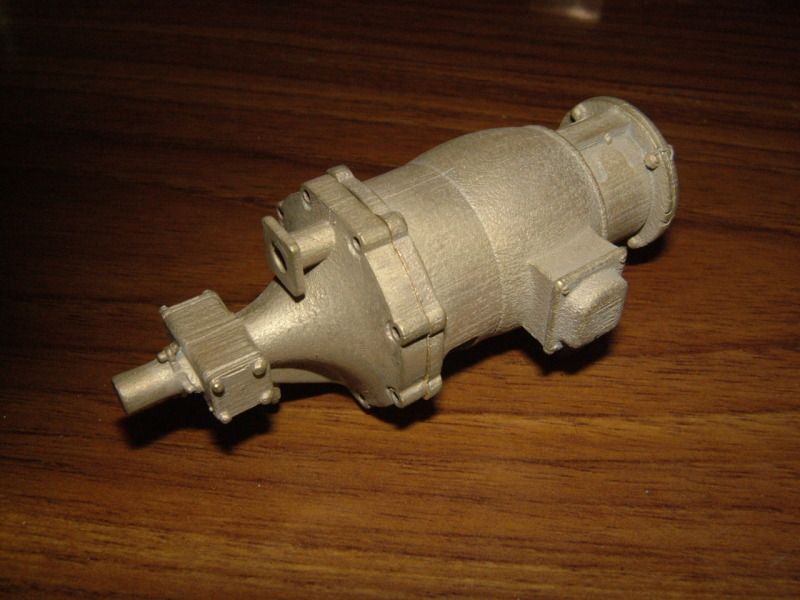 How long to fabricate this 5" gauge turbo-generator , more than the 30 quid casting , which would be impossible without 3D cad |
|
|
|
Post by suctionhose on Jan 17, 2017 20:40:05 GMT
Items like these due to their small size and fine detail a really what the present state of the investment casting industry are catering for. Just email the file and wait for the post.
I've used them too sometimes.
|
|
abby
Statesman
Posts: 925
|
Post by abby on Jan 17, 2017 21:34:35 GMT
Your opening post tells of how , over christmas , you learned 3D cad drawing in order to draw the ploughing engine part , now you say you have used online casting services before"just email the file and wait for the post".
This begs the question "how did you obtain the 3D drawing files required to produce the pattern ?
In actual fact a little more is involved than "just email the file and wait for the post" , like 30 years experience in making rubber moulds that allow the wax patterns to be removed without damage for a start.
And Harry Potter may say "Bronzium transformium" but I haven't got a magic wand so I have to make the moulds myself , melt the metal and pour.
But before all that of course the 3D drawing is required.
"small castings" like these are certainly not representative of the investment casting industry by any means although they may somewhat represent the limitations of the home foundry.
Certainly I cater for highly detailed parts and 3kg is about as big as I want to cast but I have done much larger in the past , nowadays I cast for fun and my own satisfaction.
|
|
|
|
Post by suctionhose on Jan 17, 2017 23:09:29 GMT
Sorry. I should clarify. I have purchased low cost dummy details from a supplier and used them on my models. Sometimes they are so inexpensive that they can't be passed by. (I didn't mean to be dismissive of your generator)
In fact, said supplier was not computer literate at all and used the make a master by fabrication (even 13ba wing nuts) from which the rubber mold was made and tree built up to cast several pieces in one shot.
The fellow that suggested F360 to me had a dummy valve assembly made by Shapeways with nice results.
My "Christmas part" exceeds Shapeways capacity, was rejected by a Sydney firm for the same reason. The Melbourne firm said "At least $1000". The sand casting foundry said "minimum qty 100 units"
Assistance generously offered by members of this site involved patching together multiple pieces or involving middlemen etc.
I then concluded this was the wrong way to go about it. Other options exist that are better aligned with my way of working.
|
|
|
|
Post by atgordon on Jan 18, 2017 2:46:38 GMT
If you are old enough to remember when this thread started (or is it young enough to have the power to follow it over multiple pages), I did promise PeteH that I would look at his 2D AutoCAD to 3D Fusion360 problem and see if I could help. Pete gave the info on the balanced beam engine he was looking at building, and I was able to find the PDF on the John Tom website. (Look for the Dykstra balanced beam engine drawings - a great design and a lot of info if you wanted to build the engine too). I went ahead and created a Fusion360 model of the beam of the engine: a 2D image from the PDF can be seen below ... (if you want to follow along, print it out since I was using a 2 x 24 high res monitor system with the PDF on one screen and F360 on the other) Autodesk has this really neat way of seeing how someone created a drawing. I was going to send this to Pete as a PM, but then decided that I would share my rather feeble 3D skills with all who are interested in seeing Pete's beam created in a 3D world. Click on the this link to see my attempt! If you are a F360 user, you can download the link and load the file in your workspace. If I was going to do this again, I would draw one quadrant and mirror to the right, and then mirror both to the bottom, and then edit the RHS recess and add the hole. Probably a 10 minute job second time round. Also, I would make sure that the "Constraints Window" was visible in the Screencast (I now know how to do that!). OK, Pete, now you know how to draw it, how long will it take you to draw and assemble the entire engine? I recon a day at most, or if you need sleep, maybe two! We want a Screencast of the assembly within a week ;-) Tony ...  |
|
|
|
Post by suctionhose on Jan 18, 2017 5:12:10 GMT
Thanks Tony for doing that for us. My experience was much the same as yours - lots of back and forth the time line to tweak sketches.
How would you rate that in terms of other 3D drawing? It seems quite tedious to create even a simple part like the beam.
I believe you said you'd drawn a whole super simplex! Must have taken months! For a collection of assembled parts do you draw separate "projects" and somehow connect the pieces at the end?
|
|
jasonb
Elder Statesman

Posts: 1,209
|
Post by jasonb on Jan 18, 2017 8:21:45 GMT
For a collection of assembled parts do you draw separate "projects" and somehow connect the pieces at the end? I draw each part and than make sub assemblies for example on a stationary engine I may have cylinder assembly, crank ass, conrod ass and so on. Then I will have a complete assembly. It makes the files more managable if you do it this way once you get lots of parts. If the parts are assembled in the right way then as I mentioned before it is easy to just hold the mouse button down on say the crank pin and then rotate it. This will then get teh whole engine "working" so teh cross head and piston will move, eccentric will activate the valve rod etc. From this you can see if anything will hit, click "section" on say the valve chest and valve then you can see how that is moving in relation to the ports. This is for Alibre but F360 should have no problem doing the same from what I have seen. Best thing over traditional methods is that if one part needs altering I can easily do that and the correction will be carried through to all the sub asemblies and the main assembly. Abby also makes a good point about visulisation, if designing the model yourself you will have the part in your head and know what it is meant to look like but if sharing teh drawings it may not be so clear to others what it will be like so you can easily add a small isometric or perspective of the part to the 2D drawing. J |
|
|
|
Post by Roger on Jan 18, 2017 8:59:26 GMT
Thanks Tony for doing that for us. My experience was much the same as yours - lots of back and forth the time line to tweak sketches. How would you rate that in terms of other 3D drawing? It seems quite tedious to create even a simple part like the beam. I believe you said you'd drawn a whole super simplex! Must have taken months! For a collection of assembled parts do you draw separate "projects" and somehow connect the pieces at the end? Hi Ross, You will develop ways of drawing things that make them much easier to modify as you get more proficient. I use constraints to keep lines at tangents to circles, lines parallel to others and such like. Some of them get automatically added when you draw them anyway, but you're not aware that this is what's happening when you start out. Look for the little indicators at or near the lines to see what constraints have been applied. Dimensions also keep things related and anchors can stop features from moving, although that's a blunt instrument. When I started, I used to draw all of the fillets and chamfers on the 2D sketches. These days everything is squared off and those are added on the 3D model, not the sketches. This makes it easy to apply a change across a range of features with one change. If you define an array of holes, just dimension one and make the others equal to it. Alternatively, draw one as a feature, and then create an array from that. Either way, you change one, and you change them all. It's quite possible to draw that beam in such a way that you could change the centre distances and have it all adapt to suit. It's a matter of 5 minutes work to draw something simple like that if you go about it the right way. I have a parametric model of a Cap screw, 'O' ring and a classic gland shape ie two ears with holes in around a central larger boss with a hole. I use the ideas mentioned above but also take the trouble to name the dimensions. You can then save a copy of the 3D model, and simply change the named dimensions in the table to instantly get the size and proportions of the part you need. I'd recommend anyone using 3D modelling to have a go at this because it will make you look differently at the way you model things. It really doesn't take long to model things once you take advantage of all of these tools, but you have to take the trouble to figure out where the benefits lie. |
|
peteh
Statesman
Still making mistakes!
Posts: 760
|
Post by peteh on Jan 18, 2017 12:21:07 GMT
Many thanks for spending the time to show me/us how to go about things in f360. I will have to study it in detail and try my own attempt. One of the hassles I ran into was trying to do this on a fairly old and slow laptop - switching between programs is painful to say the least! However it's all I have so will have to do but learning from the video tutorials on the f360 site was a pain.
Pete
|
|
abby
Statesman
Posts: 925
|
Post by abby on Jan 19, 2017 15:09:00 GMT
This has been an interesting thread and I was particularly interested in Tony's video , I have to say that it is far more complex than my prefered ViaCad , but then I would , wouldn't I ? But just a point that illustrates the benefit of doing the 3D drawing and model. The centre of Tony's 2D drawing shows 3 concentric circles , 6 ,9 and 13 mm diameter (some dimensions are cut off but can be found) Although the 3D model is shown correct to the original Dykstra drawing if it had been made to Tony's drawing it would look like this  Just a small point , and I think it looks better anyway but it does show how a drawing can be mis-interpreted. Hope I haven't made a mistake , wouldn't be the first time ! Dan. P.S. I have left the centre bearing out. |
|
|
|
Post by atgordon on Jan 19, 2017 17:26:34 GMT
... The centre of Tony's 2D drawing shows 3 concentric circles , 6 ,9 and 13 mm diameter (some dimensions are cut off but can be found) Not sure I understand what is being said ... ;-) I used the 9mm hole and 13mm trimmed arcs, and followed the layout from the 3D beam shown above the 2D drawing, so no radii flowing from the 13mm arc. Tony  |
|
|
|
Post by atgordon on Jan 19, 2017 17:51:07 GMT
.... It seems quite tedious to create even a simple part like the beam. How would you rate that in terms of other 3D drawing? I believe you said you'd drawn a whole super simplex! Must have taken months! For a collection of assembled parts do you draw separate "projects" and somehow connect the pieces at the end? "How to's" always take longer. I drew the beam earlier today with 2 x mirrored sketch and it took 8 minutes. All drawings take time, and as your fluency improves with the package of choice, so will your speed to complete models. Hell, it would take me at least 8 minutes to draw the beam in Autocad! I've used Pro/E (now Creo) and Solidworks in the past, and both are very powerful, and so have a lot of features that can confuse the beginner. I've found that F360 seems to be easier for me to use, and I have become "productive" without having to devote a lot of time to just learning how it works ... YMWV! I have a full set of 2D AutoCAD drawings for the Super Simplex, the majority from the late Robin Smith, a Canadian ex-pat s/simplex builder who had worked as a CAD draftsman, with a few more from baggo related to the 0-6-2 long simplex idea that he has designed, plus a few of my own! I have 3D CAD models of the parts that are known to be problematic on the S/S so I can determine how to "fix" the issues on the original drawings, rather than the entire engine! It is cool to be able to see the entire motion at work, and to be able to check clearances and adjust things in real time. A number of folks have mentioned how they go about drawing 3D assemblies: F360 works well (for me at least!) with sub assemblies. For example, I have the cylinder block, steam chest, slide valve, covers, piston, piston rod, guide bars all drawn up as components all in a single drawing (plus a balanced valve version too). Initially modeled as separate parts, and then assembled as a functioning unit (the piston and slide valve moves in and out the full length of the cylinder). Each item can be selected separately for creation of 2D drawings, and copied to a new drawing model to create the CNC machining programs. |
|
peteh
Statesman
Still making mistakes!
Posts: 760
|
Post by peteh on Jan 20, 2017 11:40:30 GMT
The 6 and 9mm diameters together refer to a bronze bearing, not the beam itself. Just drawn 'in situ' for simplicity and conserve paper space - Jan's plans are always reduced to the absolute minimum of pages, or at least that's how it seems to me. The original beam on jan's plan is shown with straight edges to the central area, although the arced ones do look nice, Tony was working off of Jan's plan not the original design.
|
|
jasonb
Elder Statesman
Posts: 1,209
|
Post by jasonb on Jan 20, 2017 16:14:31 GMT
The 13mm circle on the drawing is not solid, look closly and you will se its a line - dash - line so really just indicates the circle that the 4 tangental lines touch with a small arc top and bottom as Tony drew it.
Yes Jan'd drawings always seem very crowded to me. I could understand it if they were paper drawings but with them being shared digitally whats a sheet or two of paper.
|
|
|
|
Post by atgordon on Jan 20, 2017 19:56:03 GMT
Yes Jan'd drawings always seem very crowded to me. I could understand it if they were paper drawings but with them being shared digitally whats a sheet or two of paper. It's a pity that he didn't post the Inventor 3D file used to generate all the 2D drawings! That would have made the need to redraw in 3D completely unnecessary! |
|
peteh
Statesman
Still making mistakes!
Posts: 760
|
Post by peteh on Jan 21, 2017 6:58:35 GMT
Tony,
A further question please. I have now drawn the sketch OK and have started the extruding. I first extruded the inner sections in one operation but now my sketch has disappeared and I only have the new body. How the hell do I show the sketch to be able to extrude the outer area!
TIA Pete
OK, deleted all extrusions (bodies) and re-extruded and worked this time! Very slow internet in Australia makes this sw a pain to use!
|
|
jasonb
Elder Statesman
Posts: 1,209
|
Post by jasonb on Jan 21, 2017 7:42:57 GMT
Can't help with how to do it in F360 but I would have extruded the part full thickness equally about the central axis and then ectrude cut the recesses on one side and then mirrored that to the other side. This would save having to draw the outside shape again, edges of the cutouts can be set to run parallel to the external shape and just inset 1mm.
|
|
r707
Active Member

Posts: 30 
|
Post by r707 on Jan 21, 2017 11:48:12 GMT
Hi All - Been reading past entries with interest - and one thing that I've noticed missing in the "justification" of time spent in learning / using 3D CAD is the word "parametric". Put simply - this is the ability to change a dimension within an assembly (ie. a hole diameter), then the part rebuilds itself with the updated dimension (also any 2D dwg of the part). Part sketches within assemblies can be associative (or constrained) to other critical features or sketches (for example; a centre-line) so that if dimensions are altered it will always be aligned about that same centre-line. With time and practice, this is the real power of 3D CAD and makes modelling fast and efficient - saving an inordinate amount of time later on when cutting metal. The ability to check working clearances and trying variations on optimise parts saves time- energy and money down the track. The down side is that this parametric modelling function is generally not been available in cheaper CAD packages - until now. I suggest those interested check out Onshape - the first entirely cloud-based 3D CAD modelling program requiring no software downloads. ( free use up to 5 parts) Also - because its cloud-based it allows collaboration on CAD models where continents separate model engineers. www.onshape.com/And now; New software called FreeCAD that allows parametric modelling. I've yet to test it out, but it appears promising. Best of all its available for both PC and Mac platforms (personally I'm a Mac user but use Bootcamp to run 3D CAD programs) www.freecadweb.org/So take advantage of whats available, and make the tools work for you. Below is a pic of the R class locomotive I designed while learning Solidworks at university. The assembly is constrained in such a way to allow the motion and valve gear to operate simulating the valve events. R classCheers, ± Phil |
|
|
|
Post by atgordon on Jan 21, 2017 14:32:30 GMT
Tony, I first extruded the inner sections in one operation but now my sketch has disappeared and I only have the new body. How the hell do I show the sketch to be able to extrude the outer area! One of F360 "helpful features' is to turn off the sketch used for the extrusion "to improve clarity"! To make the sketch visible (or invisible if it is causing confusion), look for the Sketch tab on the left hand side of the screen; "open" the tab by clicking on the arrow, and you should see all the sketches used in the body being worked on. The one used for the extrusion will have the Light Bulb turned OFF; click on the bulb to Turn it ON and bingo, you can see the sketch again. You will use this turning on and off quite a lot, since F360 seems to turn things off somewhat arbitrarily: watch out for planes being turned on and off too, sometimes mid drawing. I think I PM'd you my email address: since ME Board doesn't inform me of posts in topics I'm following, it might be better to email me any questions you have. And the F360 forum is an excellent source of info |
|
|
|
Post by atgordon on Jan 21, 2017 14:46:47 GMT
Hi All - Been reading past entries with interest - and one thing that I've noticed missing in the "justification" of time spent in learning / using 3D CAD is the word "parametric". Put simply - this is the ability to change a dimension within an assembly (ie. a hole diameter), then the part rebuilds itself with the updated dimension (also any 2D dwg of the part). Part sketches within assemblies can be associative (or constrained) to other critical features or sketches (for example; a centre-line) so that if dimensions are altered it will always be aligned about that same centre-line. With time and practice, this is the real power of 3D CAD and makes modelling fast and efficient - saving an inordinate amount of time later on when cutting metal. The ability to check working clearances and trying variations on optimise parts saves time- energy and money down the track. For parts that I am designing for CNC machining, I use only parametric entries for the reasons listed above. There is a small price for the extra time taken to declare all variables and (if used) calculations, but very worthwhile when creating a new version of your favorite widget in seconds. For the s/simplex stuff, I am generally trying to work out part interaction and clearance problems, so I have to use actual dimensions from Evans design. F360 is both hosted (natively on Mac and PC) and cloud based for file storage or group collaboration design work. When the Autodesk cloud server crashed in December for over a day, I was glad it kept local copies of what I was working on! The cloud does mean that you are relying on someone else's systems to get work done. |
|


