|
|
Post by Roger on Mar 29, 2018 22:09:20 GMT
I'd really like to have another three of the Dickson S2 toolholders but cringe at the £80 they want for each one. It's not expensive when you consider how much work is in them, but since I've made a few before using the old Southbend lathe I had, I thought I'd make some on the CNC mill this time. I modelled it and then found that I had this big lump of Mild Steel bar which is just big enough to make them from. Now, you may well ask why I would do that rather than get some rectangular stock that's nearer the size. The reason is two fold. Firstly, cold rolled bar isn't that nice to machine compared to most round bar stock. Secondly, this will be more rigid while I'm machining the first of them. Yes, I know I could have machined it 'Old school' by machining rectangular block, one face at a time to end up with a lump that's the right size, but that involves a lot of faffing about with multiple setups. This way I can program it and let it get on with the job while I do something more interesting. 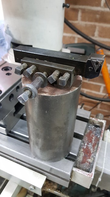 20180329_114644 20180329_114644 by Roger Froud, on Flickr The big face mill was used to clean up the top surface manually. The next ones will be faced off in the lathe. 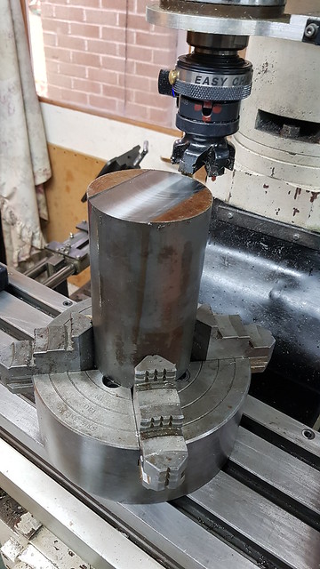 20180329_144758 20180329_144758 by Roger Froud, on Flickr Here I'm checking the centres of the Vees, I wasn't sure if the drawing I found on the internet was right. 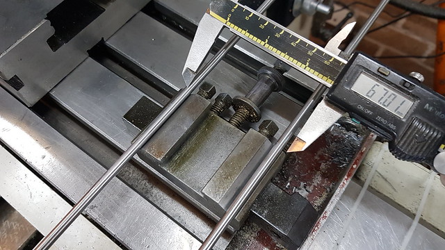 20180329_103500 20180329_103500 by Roger Froud, on Flickr Anyway, this is about software and how to go about machining something like this. I'm not claiming that this is a great way to do it, someone in a commercial shop would have a fit if this was proposed when time was of the essence! So this is the first operation. It's a 2D profiling one, there's a rectangular Orange sketch projected onto the top surface of the model to guide the tool. I'm using a 16mm ripper because that's long enough for the 31mm depth required. Actually I only need just short of 30mm, but it's best to avoid making the depth exactly the same as the finished part because the tool will never cut a square corner at the bottom. I'm only using 1mm cuts and a very shallow 2.5 degree entry slope because the first of these it standing a long way out of the chuck so it's not as rigid as I would like. It will get better on subsequent ones. 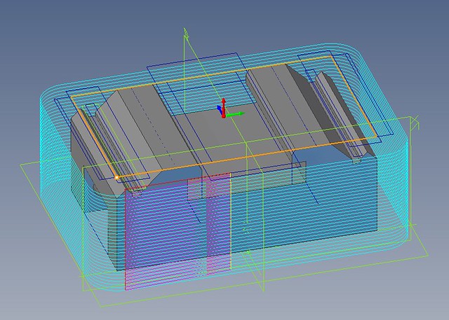 Rough profile Rough profile by Roger Froud, on Flickr Here's a wobbly video of that operation. 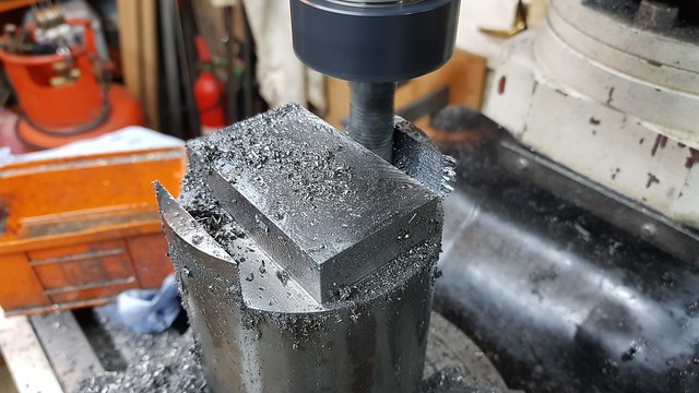 20180329_172105 20180329_172105 by Roger Froud, on Flickr While that cutter is being used, the next thing is to remove the bulk of the material from what will become the Tee slot. Again, the driving sketch is in Orange and the blue lines are the centre line paths of the various passes. This time I'm using a Pocket machining operation. 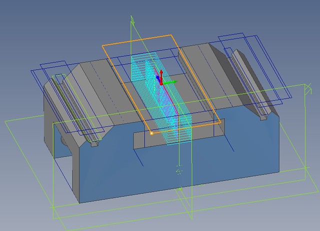 Rough centre Rough centre by Roger Froud, on Flickr And that results in this... 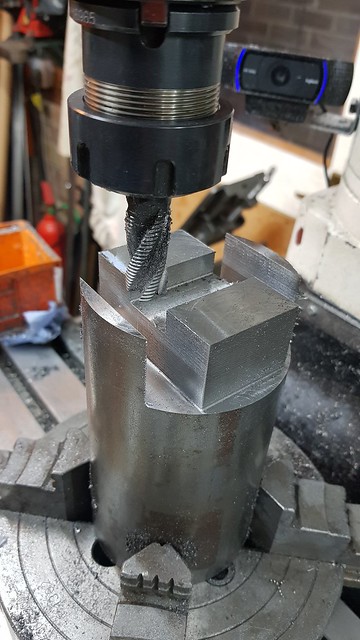 20180329_194803 20180329_194803 by Roger Froud, on Flickr I group operations using the same tool under the same machining operation and drag them into a common tree, similar to the way it's done in Windows. There's too much material above the Vees to start following the overall contour, so the next thing is to switch cutters to a 6mm ripper and face off an area there. This again uses a Pocketing operation.  Rough above vees Rough above vees by Roger Froud, on Flickr The result was this, which is not quite what I intended. I'd forgotten that leaving stock meant also not quite reaching the edge, to those have to be broken off with pliers before continuing. I make adjustments to the program as I go along for the next one. In this case, the containment sketch was extended another 0.5mm past the edge of the finished part. 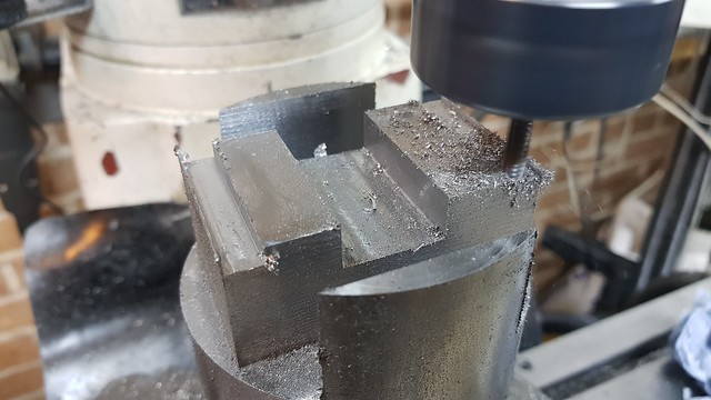 20180329_201737 20180329_201737 by Roger Froud, on Flickr This step uses Parallel Finishing with a 0.3mm offset and the Orange containment sketches to remove the bulk of the material for the chamfer leading into the Tee slot. This is very coarse, using a step over of 2mm 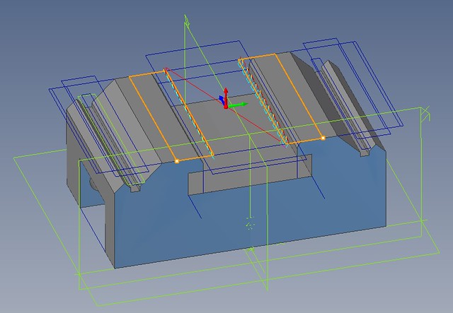 Rough inner chamfer Rough inner chamfer by Roger Froud, on Flickr The outer Vees are roughed along the final profile path but several millimeters above. The idea is to quickly knock the square corners off, again with coarse cuts, keeping the wasted time to a minimum by containing the machining within the Orange containment bounds. 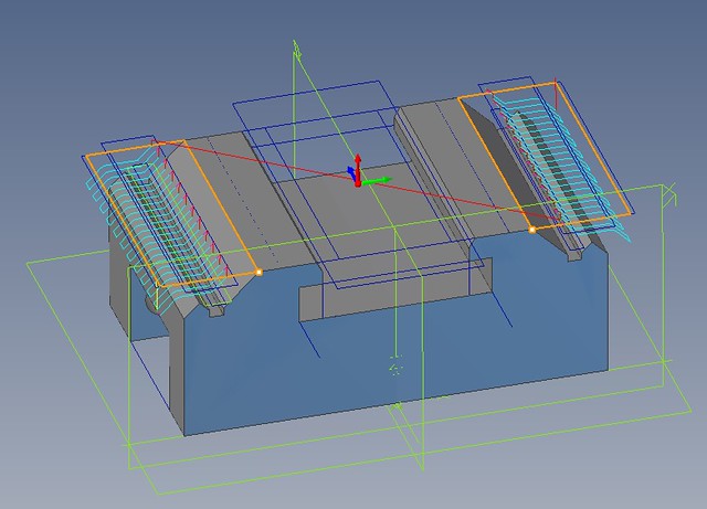 First rough of vees First rough of vees by Roger Froud, on Flickr There are three of these, each one getting closer to the final size. The last one is still 0.3mm above the finished surface. The idea is to rough the out as quickly as possible without having to worry about damaging the final surface. Here's the last of the three. 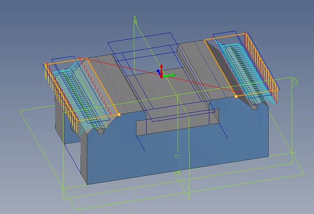 Last rough of vees Last rough of vees by Roger Froud, on Flickr Again, all the 6mm ripper operations were combined into one machining operation so they could be done one after the other without manual intervention. You can see that the next issue is that there's a missing Vee that couldn't be reached with the 6mm ripper. The key to getting these jobs done in a reasonable time is to use as bit a cutter as you can to start off with but always be aware that you're going to have to keep stepping down to a smaller one to get into all the features. In this case, I'm going to have to go down to a 2mm cutter to finish this job. Switching to a small size too early can add many hours to a program. it's easier to program, but the times quickly become unacceptably long. 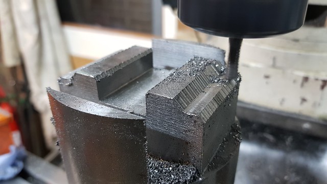 20180329_214105 20180329_214105 by Roger Froud, on Flickr |
|
|
|
Post by Roger on Mar 30, 2018 9:49:09 GMT
The next step is to get into the awkward Vee shape that has so far been missed by the larger cutters. Here I'm using a pocket, again defined by the containment in Orange, to reach down into the base of the undercut at the root of the Vee. This is using a 2mm slot drill and 0.5mm deep cuts. 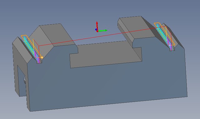 Rough vee root clearance Rough vee root clearance by Roger Froud, on Flickr The flanks of the Vee now need to be roughed to knock the sharp corners off like this. I'm using a Parallel Finishing operation leaving just 0.1mm 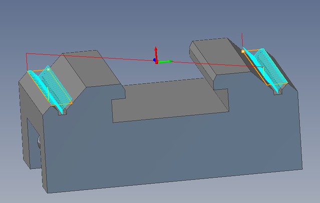 Rough inner vees Rough inner vees by Roger Froud, on Flickr Those passes leave the job looking like this. 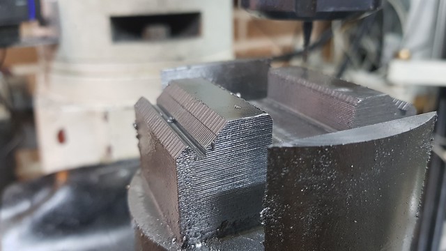 20180330_101643 20180330_101643 by Roger Froud, on Flickr |
|
|
|
Post by Roger on Mar 30, 2018 13:40:45 GMT
Now we get to the finishing stages with a 2mm Ball nosed cutter. You can see that there's not a lot of cutting length, nowhere near enough to reach to the bottom of the central section. 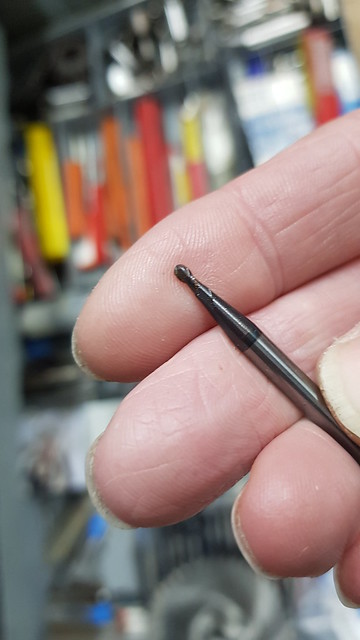 20180330_104945 20180330_104945 by Roger Froud, on Flickr So a couple of Orange containment regions have been set up to stop it from plunging into the middle. This is a coarse pre-finishing cut using a Parallel Finishing operation leaving 0.05mm stock and using a 0.75mm overlap. This removes the bulk of what's been left by previous roughing strategies and gives an even starting point all over for fine finishing. 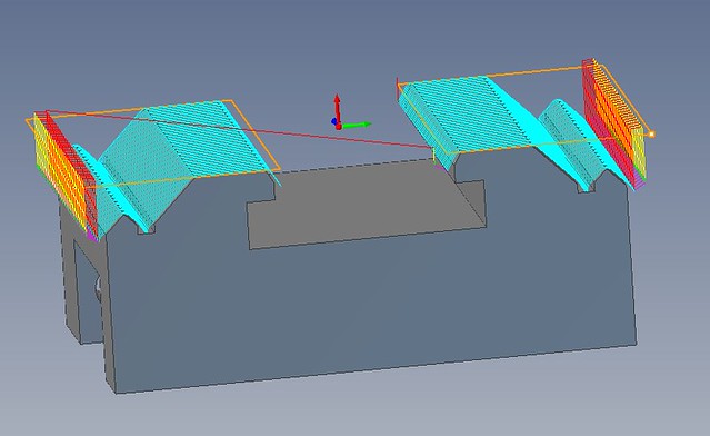 Pre finish Pre finish by Roger Froud, on Flickr And this is the Parallel Fine Finishing operation to the final size using a 0.1mm overlap. Initially I tried a 0.2mm overlap but the finish was unacceptable. 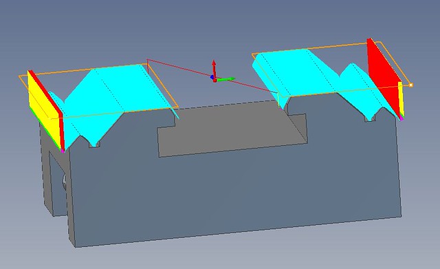 Fine finish Fine finish by Roger
Froud, on Flickr The final finishing looks like this, and here's a wobbly video to give you an idea of the feedrate. It's 350mm/min so you wouldn't want to run into something that was left from a previous roughing operation. The idea is to give a quick clean up first and then really ramp up the speed of this final cut else it takes forever. The final cut takes 1hr:40min while the much slower Pre-finishing cut took 40 minutes. 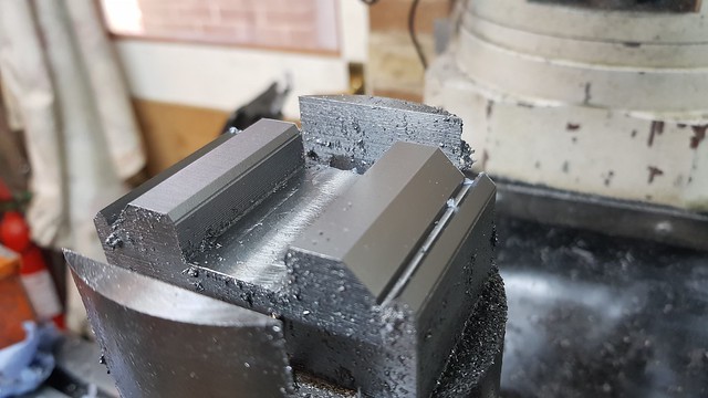 20180330_141551 20180330_141551 by Roger Froud, on Flickr |
|
|
|
Post by Roger on Mar 31, 2018 9:23:38 GMT
After sawing off the bar, the top was cleared with a series of cuts with the face mill, all of the commands being entered manually from the command line. I could have used a Facing operation, but they tend to generate long and bizarre paths that leave a messy trail on the surface. It looks much nicer to have one clean cut in a single pass. I very rarely use a Facing operation for this reason. 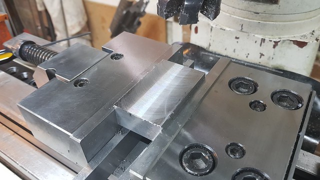 20180330_170507 20180330_170507 by Roger Froud, on Flickr The cutout for the tool was done with an open ended sketch, again shown in Orange. Since I know that this is going to be cleared using a 16mm tool, I can use a Profiling operation instead of a Pocketing one. In other words, the tool is big enough to cover more than half of the slot width, so just going around the profile will clear the middle anyway. This time I've defined an open ended path so I can plunge into fresh air beyond the end of the work. This is the roughing cut with a 16mm ripper and 40mm/min taking 1mm deep cuts. I've defined a new model for this in the right orientation since my CAM package is a base model where you can't define multiple axes definition and orientations. 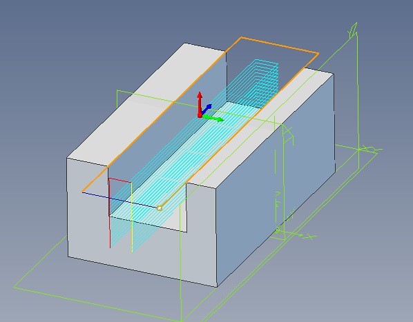 Tool slot roughing Tool slot roughing by Roger Froud, on Flickr The finishing pass takes much deeper cuts at a higher feed rate. 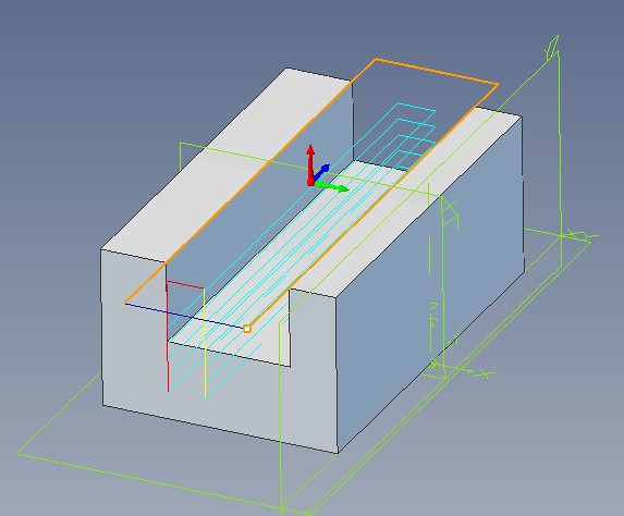 Tool slot finishing Tool slot finishing by Roger Froud, on Flickr That looks like this. 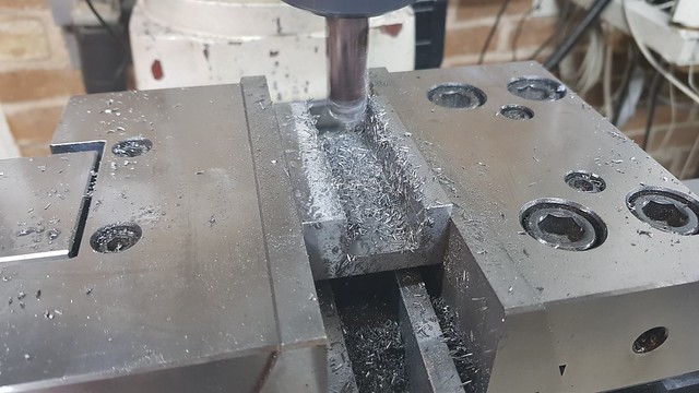 20180330_183403 20180330_183403 by Roger Froud, on Flickr After a quick clean up, it looks like this. 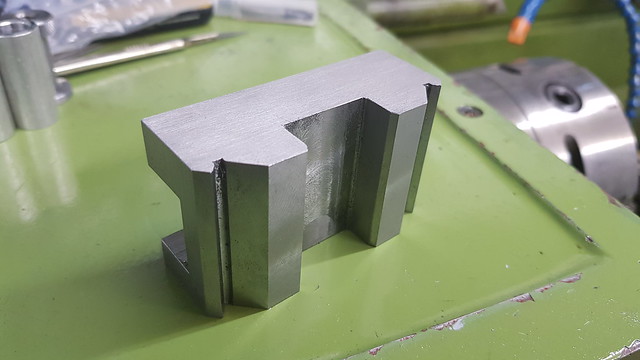 20180330_204400 20180330_204400 by Roger Froud, on Flickr The Tee slot is in the right orientation on the original model, but you can see that this path has been defined differently to all of the others. Here, the Orange sketch it's following is set to the bottom of the feature and not the top. Usually there's a depth that needs to be progressively changed, so you need to start at the top and work down. In this case, the cutter is the height of the cut I need to make, so the depth of cut is set to zero and the tool just follows the profile. I've used an open ended path again for this so that I can control where the tool plunges and leaves the start and end of the tool path. Obviously you wouldn't want it catching the narrow part of the Tee! I could have used a pocketing operation for this, the pocket would have needed to be much larger than the area to be machined so that the entry and exit could be made clear of the ends. The way I've done is results in a shorter cycle time because I can move from one side of the cut to the other as the centre line of the cutter clears the end. That does mean that I have to copy and paste the operation 8 times and use a different offset for each one. You have to weigh up the pros and cons of each decision, it's not a Black and White decision process. 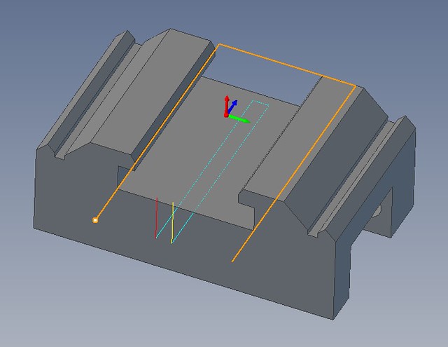 Tee slot1 Tee slot1 by Roger Froud, on Flickr I'm taking 0.5mm deep cuts at around 150RPM and 20mm/min so it's pretty gentle. I could have done this before taking the round bar out of the chuck, but I thought the overhang would cause a lot of chatter. CNC milling uses Climb Milling wherever possible because the finish is so much better, and the last thing I wanted was for it to grab the work and pull it over in the 4-jaw. When I to the last one, it might be rigid enough on the shorter bar to do it that way. 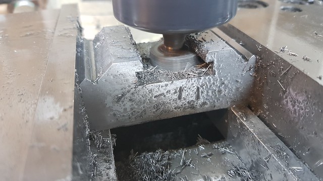 20180331_101841 20180331_101841 by Roger Froud, on Flickr |
|
|
|
Post by Roger on Mar 31, 2018 14:28:35 GMT
All of the tapped holes are M8, they're Imperial on the original but I'm allergic to things Imperial so I've changed it. The holes are created using a Drill Cycle which has loads of parameters I don't need. I just set up the Spindle speed for this. My mill has a powered knee for the Z-axis, the Quill is still manual. This is where that arrangement comes into its own, because I can use a utility program I wrote to rip out the unwanted cycle commands and convert them into linear moves instead. This means I can single step between holes without any Z-axis changes and I can use the Quill for drilling and supporting the tap. Drilling under power is fine if there are many holes, but I find it's easier to control what's going on with this semi-automatic method. You can select optimisation so that each hole is close to the last or on a zig-zag path. The CAM software would otherwise output the holes in the order they happen to have been created in the CAD file, and that might be far from an optimal path. As usual, I make the centre and top of the job the zero point and use the wobbler to find the centre from the vice jaws or the job ends. You can see the Triad that shows the zero position at the top of the model. 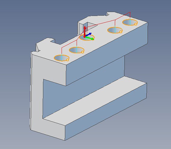 Tapped holes Tapped holes by Roger Froud, on Flickr 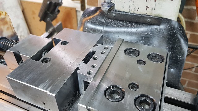 20180331_145106 20180331_145106 by Roger Froud, on Flickr The bobbin is a simple turning job, and a short length of Stainless Steel studding was used for the adjuster which was secured with Loctite. 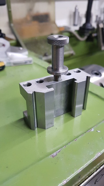 20180331_150634 20180331_150634 by Roger Froud, on Flickr I've ordered these high tensile flanged bolts from eBay for the Square clamping bolts. I looked everywhere for them as a finished item, but could only find them in large quantities. The idea of buying flanged bolts is to provide more length of material that can be machined square. 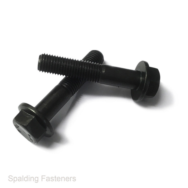 Flanged bolt Flanged bolt by Roger Froud, on Flickr |
|
|
|
Post by gwr14xx on Mar 31, 2018 15:13:28 GMT
Roger,
Leeside Tools at Yapton used to have a large stock of those square head toolpost bolts - worth a try!
Regards, Eddie.
|
|
|
|
Post by Roger on Mar 31, 2018 17:04:03 GMT
Roger, Leeside Tools at Yapton used to have a large stock of those square head toolpost bolts - worth a try! Regards, Eddie. Thanks Eddie, I'll look them up. |
|
|
|
Post by Roger on Mar 31, 2018 20:03:09 GMT
Here are the rest of the parts, including the spacers and tongues for the tool rack on the lathe. I've ordered a longer length of M10 rod to make that longer. 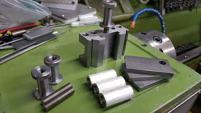 20180331_204954 20180331_204954 by Roger Froud, on Flickr |
|
|
|
Post by steamer5 on Mar 31, 2018 23:25:06 GMT
Hi Rodger,
Nice work & great explanation!
I recently made some specials for my Dickson, the baby one, measured up all my current ones, averaged the numbers, drew it up in 2D CAD, took the resultant file to the water cut guy! I must of done something right cause they fitted great! The down side.......the cost of the cutting!! I could of brought 3 holders off the shelf for the cost of 1 water cut! BUT I cant by a holder for a 20mm boring bar, or the cut knurler I built!
Cheers Kerrin
|
|
|
|
Post by Roger on Apr 1, 2018 8:13:44 GMT
Hi Rodger, Nice work & great explanation! I recently made some specials for my Dickson, the baby one, measured up all my current ones, averaged the numbers, drew it up in 2D CAD, took the resultant file to the water cut guy! I must of done something right cause they fitted great! The down side.......the cost of the cutting!! I could of brought 3 holders off the shelf for the cost of 1 water cut! BUT I cant by a holder for a 20mm boring bar, or the cut knurler I built! Cheers Kerrin Hi Kerrin, I would never have thought of using water cutting for that, there must be a lot less taper on the cut than I imagined! I dread to think how much mine would have cost to get CNC machined, there has to be around 8 hours machining time when you add it all up. As you rightly point out, being able to make special ones is definitely an advantage. I made one years ago to take a parting blade, and then I was given one that took a slightly wider one. I once visited Crawford Collets years ago, and they showed me a horizontal Gang Milling setup for machining the whole cross section of a long bar of material into these tool holders. The undercut obviously had to be machined separately. You've prompted me to make a proper drawing of this, it sounds like you struggled to find the correct dimensions too. I did find a partial drawing that showed the Vee centres, but not enough to completely tie it all down. Anyway, this is the drawing that mine are made to. 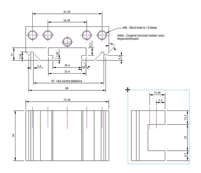 Dickson S2 tool holder Dickson S2 tool holder by Roger Froud, on Flickr |
|
milky
Seasoned Member

Posts: 120
|
Post by milky on Apr 1, 2018 18:44:18 GMT
I hasten to add Roger that's 8 hours of a very skilled machinist. Just finished the rack to hold mine  |
|
|
|
Post by steamer5 on Apr 2, 2018 16:07:07 GMT
Hi Rodger,
The guy I went to has a 2 1/2 D water jet. It compensates for the cut angle caused by the jet....well that's the way I understand it! The face was nice & square...well as best as I could figure.
The cost of cutting goes up quick as the material thickness increases, so if you double the thickness the cost doubles PLUS!! It's all about time on the table. There was an article on making my size holders in EIM, I think, a few years back, which was my starting point. I had the shape cut out of 6 mm plate to check it out, but it didn't quite fit my holder, hence the reason for measuring mine up & redrawing
Cheers Kerrin
|
|
|
|
Post by Roger on Apr 2, 2018 16:31:30 GMT
Hi Rodger, The guy I went to has a 2 1/2 D water jet. It compensates for the cut angle caused by the jet....well that's the way I understand it! The face was nice & square...well as best as I could figure. The cost of cutting goes up quick as the material thickness increases, so if you double the thickness the cost doubles PLUS!! It's all about time on the table. There was an article on making my size holders in EIM, I think, a few years back, which was my starting point. I had the shape cut out of 6 mm plate to check it out, but it didn't quite fit my holder, hence the reason for measuring mine up & redrawing Cheers Kerrin Hi Kerrin, Thanks for that explanation, it's a clever system then. Even with that compensation, I'm impressed that it seats well. I don't think there's a low cost way to make these. Perhaps they could be made using powder metallurgy, butI imagine the tooling would be expensive. |
|
|
|
Post by Roger on Apr 6, 2018 21:35:39 GMT
Just to round this project off, here is one of the M8 High Tensile Flanged bolts I bought for making the Square Headed bolts from. I'm using my standard M8 theaded bush which was made for this sort of occasion, locking the bolt firmly in place with a nut. 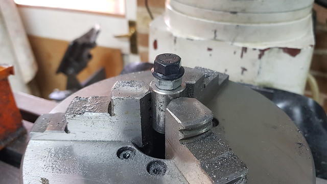 20180406_145647 20180406_145647 by Roger Froud, on Flickr It's pretty tough stuff to machine, so I've used a 6mm Ripper and only 1mm cuts. 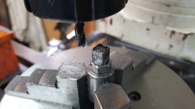 20180406_122527 20180406_122527 by Roger Froud, on Flickr It was finished off with a 10mm 2-flute... 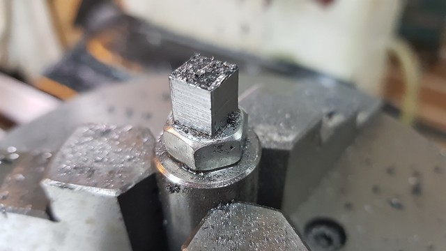 20180406_131445 20180406_131445 by Roger Froud, on Flickr ... then faced off and chamfered on the lathe. 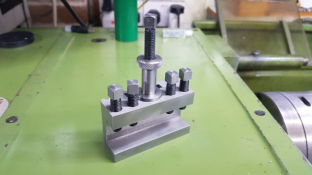 20180406_174525 20180406_174525 by Roger Froud, on Flickr This was the original rack for them... 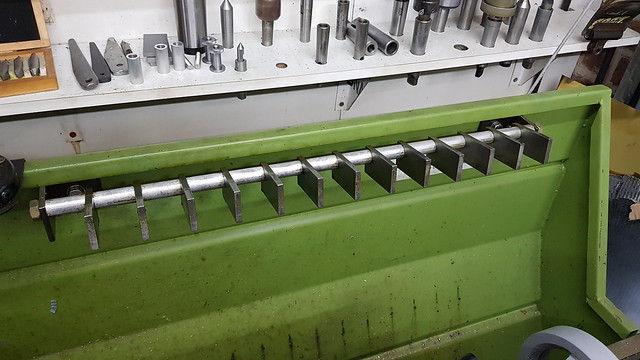 20180405_103815 20180405_103815 by Roger Froud, on Flickr ... and now there are three more places. Here I've clamped a flat piece of bar underneath so I can get them all level when the M10 stud is tightened through them. 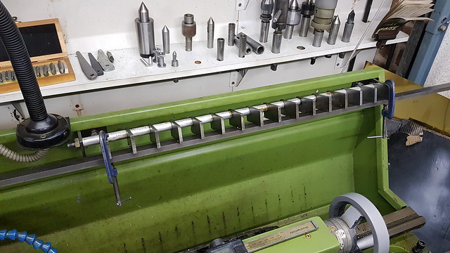 20180405_113537 20180405_113537 by Roger Froud, on Flickr Job done, just two more holders to make when I've got some spare time on the machine. 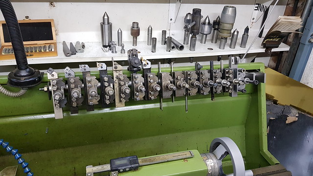 20180405_113711 20180405_113711 by Roger Froud, on Flickr |
|
|
|
Post by Roger on Apr 13, 2018 22:12:30 GMT
This is the second holder, but this time I thought I'd part it off rather than saw it. That's because it takes a fair bit of finishing off because you can't cut that close to the finished size. By parting it off, it can be taken to within about 0.3mm of the finished size. The part is 90mm diameter, so that's a pretty big overhang. Here I'm using a 3.1mm wide parting blade with no top rake an no thinning behind the cutting edge. I set the blade against the side of the chuck to get it square. 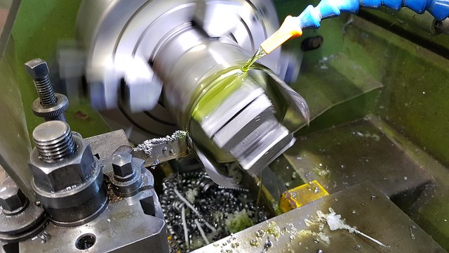 20180413_122617 20180413_122617 by Roger Froud, on Flickr This wobbly video shows how it looks when it's cutting. There's a little bit of chatter, but slowing it down slightly stopped that.  20180413_124653 20180413_124653 by Roger Froud, on Flickr 20180413_124653 by Roger Froud, on Flickr 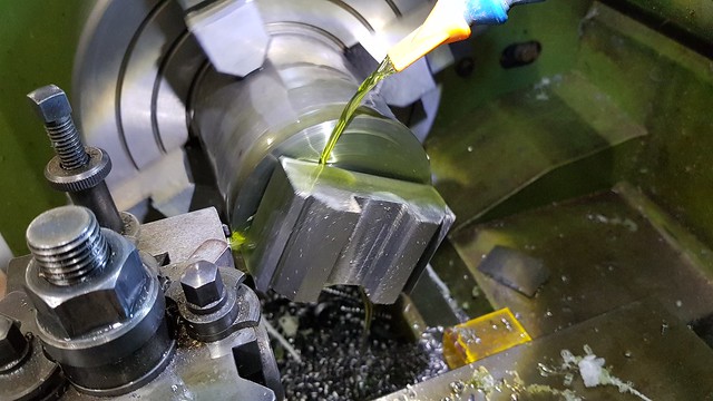 20180413_130515 20180413_130515 by Roger Froud, on Flickr I stopped it before it broke off, leaving the pip which was easily twisted off by hand. The pattern of marks left is typical of parts which have intermittent cuts. You can't get a good finish when you do this. 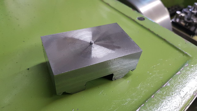 20180413_131639 20180413_131639 by Roger Froud, on Flickr Anyway, that's the second body done, just the square headed bolts to do now and add a stud. 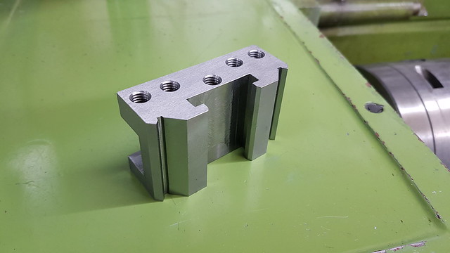 20180413_224038 20180413_224038 by Roger Froud, on Flickr |
|
sis
Seasoned Member
Posts: 113
|
Post by sis on Apr 15, 2018 12:49:16 GMT
Roger,
From the photographs and video it looks like the finish you have on the dovetail/prismatic surfaces look better than the flat. Would you agree? Based on the video is it correct that you are not using the center of the ball nose end mill for those dovetail/prismatic surface? If so this would explain the better surface finish, i.e. you are not using the "stationary/low" surface speed center of the cutter. Would you agree or perhaps I am making 2 + 2 =5.
I've seen some videos of the professionals and they tend to avoid the center of the ball nose end mills on finishing passes which I assume is for this reason. Which brings up another question has that been a strategy of yours across the speedy build?
The making of custom tool holders is of interest to me but I use the Multifix A sized QCTP system. I have a sketch of a multifix parting blade tool holder that I will try and make at some point. Tool holders are not commercially available that take the standard blades. I measured the dimensions and the spline on the A size that I use and it was not easy to be sure I have my dimensions correct. I need access to a microscope or projector scope to be sure or someone with a CMM!
Regards,
Steve
|
|
|
|
Post by Roger on Apr 15, 2018 14:33:40 GMT
Hi Steve,
It's an optical illusion, there's no real difference between the surface finish on the two surfaces. It's true that you're better off on the sloping surface, but I'm using pretty conservative feeds and speeds so there's plenty of time for the tip to do its work. I'm sure there are strategies you can use professionally to get the best surface finish with the shortest possible cycle time, but my software isn't that clever.
I guess a simple profile machined to your measurements would prove whether they were close enough?
|
|
sis
Seasoned Member
Posts: 113
|
Post by sis on Apr 15, 2018 15:15:39 GMT
Roger,
I think a simple profile and some blue will give enough information to determine if it is close. I have based the measurements off of a sanity check via the Multifix B size which is much bigger than the A and therefore easier to measure. My B size measurements tallied with a posting I found on a french language forum where someone had made there own B sized tool holders. Although down at A size it was very difficult for me to see what I was doing! One interesting difference between the original Swiss made holders and all the clones is that the spline becomes asymmetric as it moves away from the center. At first I did not understand why they had designed it this way until I examined some C size holders which are really quite large. The asymmetry provides more relief when inserting and removing the holders. I.e. they are easier to install and remove. Down at A size the benefit is marginal, hence why the Germans, French and Chinese clones don't bother with it. I have no idea if they do in the larger sizes.
I'll send you an email.
Regards,
Steve
|
|


