44767
Statesman
 
Posts: 539
|
Post by 44767 on Aug 21, 2018 10:16:25 GMT
The one piece of advice I'd give is to fabricate the stretchers leaving enough material on them to machine to the sizes on the drawing. Don't expect to fabricate to size by any method. You should only need 0.5mm per side but this will allow you to get them square and parallel and the correct size. Therefore, elements requiring machining will be thicker in the fabrication.
|
|
|
|
Post by runner42 on Aug 24, 2018 8:18:33 GMT
I have spent a whole week making the drag box, done with old procedures i.e. hack sawing and filing. I tried to use the Milling Machine to establish the cut outs but found that the work tended to move into the end mill and caused it to go over the marked out lines, must be doing something wrong! It also weighs a bit so my locomotive is going to be a heavy weight, unlike a colleague of mine who used a lot of LBSC's Doris's design principles in building his 5" gauge black 5. But the end result appears to tick all the boxes for functionality ie the critical dimensions are spot on and all the angles are square. It was quite challenging in getting to that point. Brian 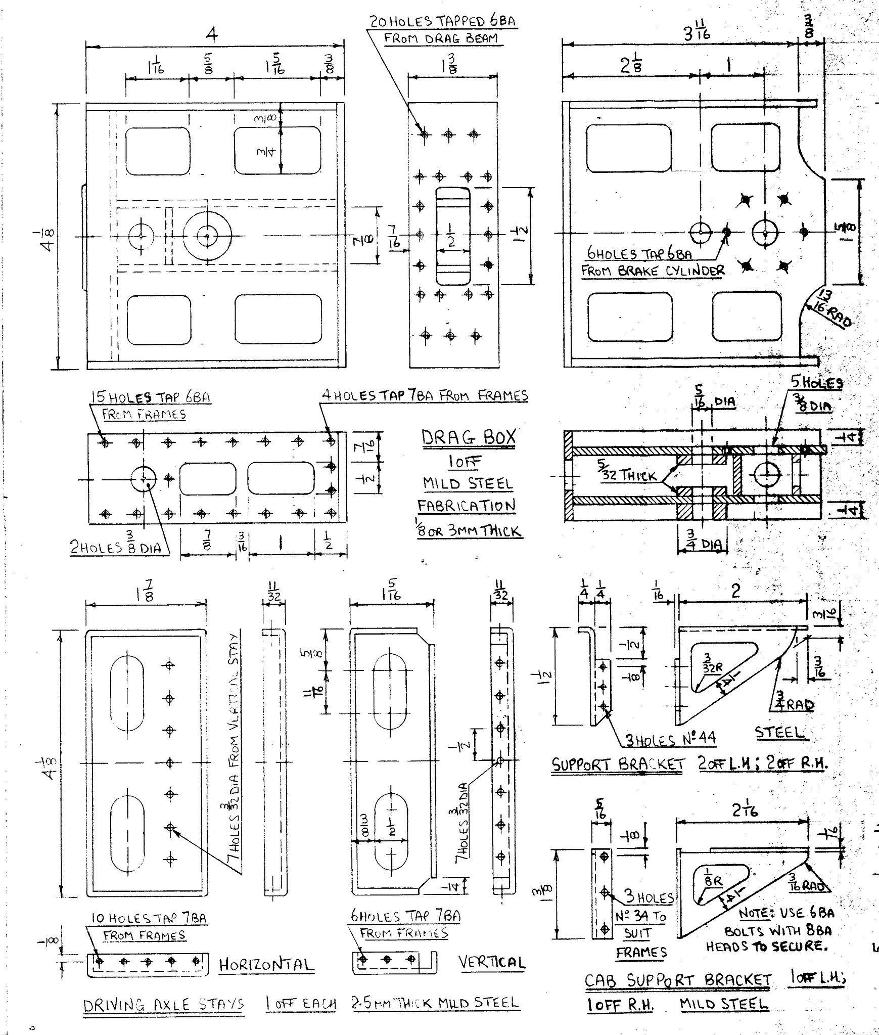 Drag Box Drag Box by Brian Leach, on Flickr 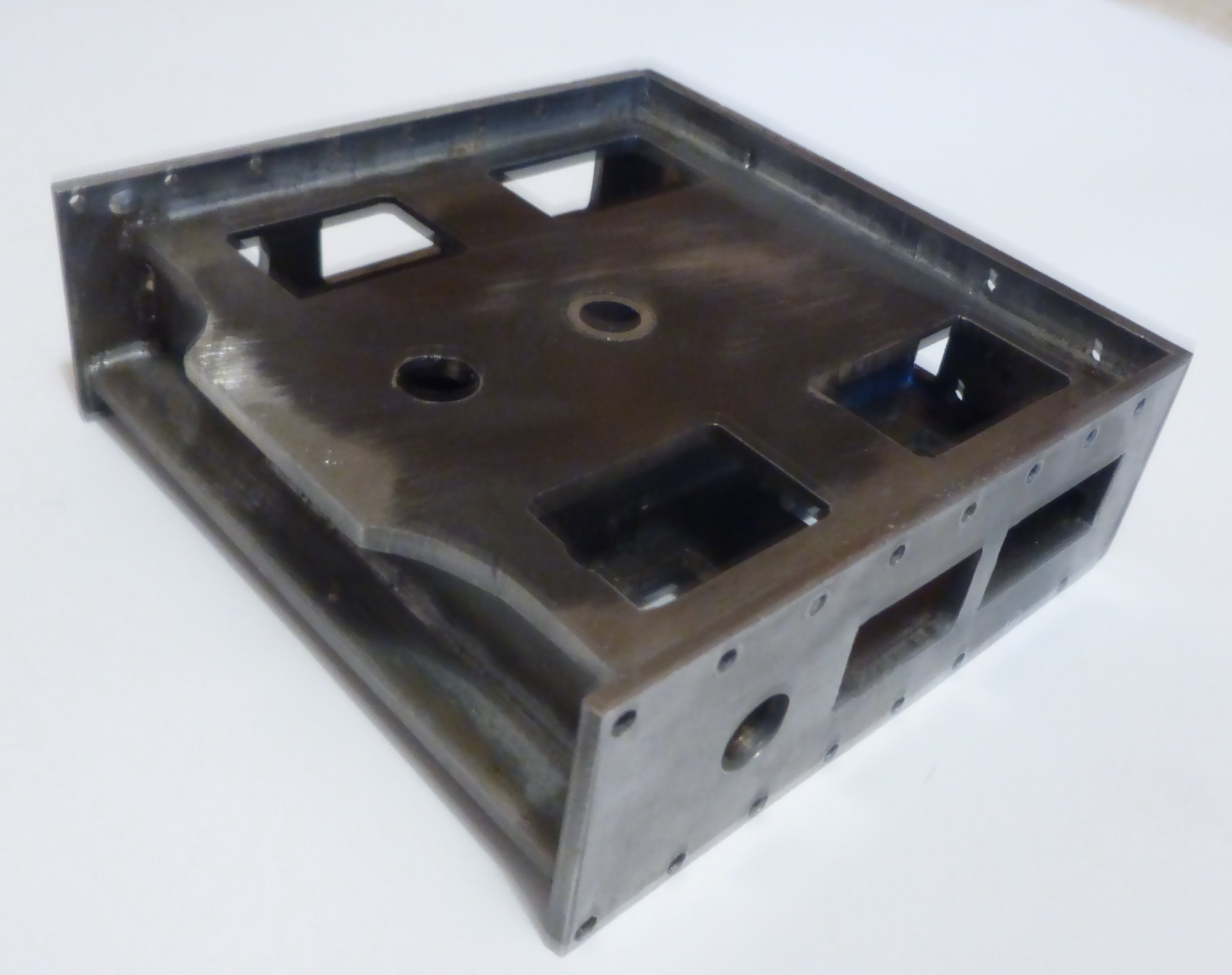 Drag Box1 Drag Box1 by Brian Leach, on Flickr 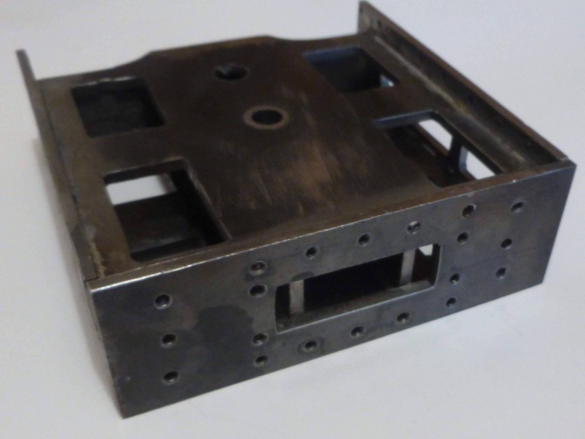 Drag Box 2 Drag Box 2 by Brian Leach, on Flickr 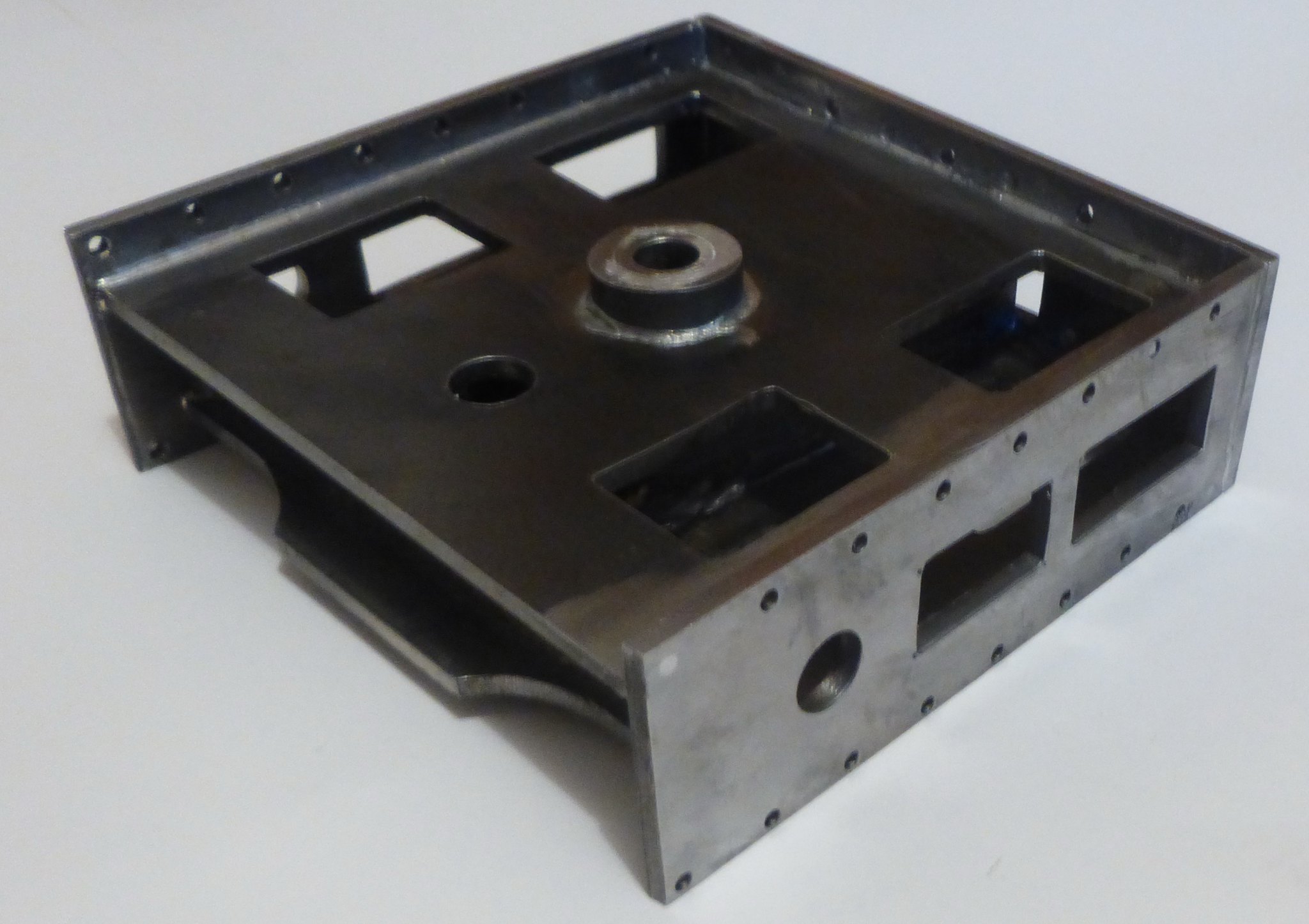 Drag Box 3 Drag Box 3 by Brian Leach, on Flickr |
|
|
|
Post by runner42 on Aug 25, 2018 7:43:12 GMT
Attention Black 5 builders! What are the boiler replenishment systems. I can't see a axle driven pump or and emergency hand pump in the tender. I assume that the only system is by an injector. AMBSC Code Part 1 requires at least two independent feed water systems. What are builders incorporating in their design.
Brian
|
|
|
|
Post by Deleted on Aug 25, 2018 8:05:36 GMT
Don's words for Doncaster are..'It would be undignified to fit a hand pump in such a model..I would guess that the black 5 is the same using 2 injectors as per prototype, this counts as two independent feed systems.
Pete
|
|
|
|
Post by Jim on Aug 25, 2018 8:45:46 GMT
Don's words for Doncaster are..'It would be undignified to fit a hand pump in such a model..I would guess that the black 5 is the same using 2 injectors as per prototype, this counts as two independent feed systems. Pete Boadicea is the same, a high pressure injector and a low pressure injector and as the injectors are independent of each other they comply with the code. If you want to add a hand pump or axle pump as extras you certainly can.
Jim.
|
|
|
|
Post by runner42 on Aug 26, 2018 4:31:57 GMT
Well having only injectors is a bit of a gamble in my situation having had no success with them both in making and purchasing. I think that having an axle pump at least is a good idea, but to incorporate it needs to make early adjustment to the stay arrangement. Also, I am thinking that a single mechanical lubricator mounted between the frames at the front is a simpler solution, so the front stay and draw bar is going to be binned. This is a significant departure from Don Young's design but I would rather have a locomotive that has a good chance of being a reliable runner than being close to the prototype.
Brian
|
|
mbrown
Elder Statesman
  
Posts: 1,793
|
Post by mbrown on Aug 27, 2018 10:14:06 GMT
On e of the problems with installing an axle pump is that it needs a fair amount of pipework which ahs to be fitted in somewhere - feed pipe, delivery pipe and by pass plus an additional clack. I felt the same as you about relying solely on injectors so I put the axle pump on the tender which means that it only needs a delivery pipe to the loco, and in my case the hand pump feeds through the same pipe with the axle pump drawing water through the hand pump. The delivery pipe and clack are fairly unobtrusive.
I haven't done any calculations but I kept the pump on the small side to reduce any risk of it locking the tender wheels when feeding against boiler pressure. IT is enough to keep the boiler topped up, but probably not big enough to fill it rapidly. Anyway, for me, it was a fair compromise between keeping the appearance of the loco to "scale" and having the insurance policy of a feed pump.
Juts a thought....
Malcolm
|
|
|
|
Post by runner42 on Aug 28, 2018 7:36:03 GMT
I don't think that having a locomotive driven axle pump is a great departure from the scale version unless you look from underneath, the above rail outward appearance is sufficiently in conformance to DY's specifications to be a fine example of what he intended. The extra pipework is rather dependent on whether you have two injectors or just one, having one and an axle pump then I would equate to having two injectors. An aside I have yet to discover whether DY has specified the pipe work arrangements, there is so much to digest. As I mentioned before a colleague has used a lot of LBSC's Doris design solutions in his 5" gauge Black 5, I have included a photo. Brian  Allan's Chassis Allan's Chassis by Brian Leach, on Flickr |
|
|
|
Post by Deleted on Aug 28, 2018 8:01:57 GMT
Hi Brian If the Black 5 is anything like 'Doncaster' there will be very little if anything re-pipework. About being prototypical or not...it's your loco..do whatever suits you best. I agree that an axlepump is unlikely to be seen when built...I would point out one thing that may not be obvious...an axlepump can make a fair bit of noise...something to bear in mind. The frames look great sir...a Don Young signature....  Regards Pete |
|
smallbrother
Elder Statesman
   Errors aplenty, progress slow, but progress nonetheless!
Posts: 2,269
|
Post by smallbrother on Aug 28, 2018 15:24:57 GMT
Hi Brian If the Black 5 is anything like 'Doncaster' there will be very little if anything re-pipework. About being prototypical or not...it's your loco..do whatever suits you best. I agree that an axlepump is unlikely to be seen when built...I would point out one thing that may not be obvious...an axlepump can make a fair bit of noise...something to bear in mind. The frames look great sir...a Don Young signature....  Regards Pete Hi Pete and Brian, When I got into the hobby in 2009 I was told all sorts of things about axle-pumps. You hit a wall when you close the bypass was the one I particularly remember. I have owned and driven 5" and 7 1/4" locos with them fitted and have nothing bad to say about any of them. Never felt or heard them when working, all that happened was the water level went up. My current loco has 2 injectors (by Len Steel) and a hand-pump. After a bit of pipework and clack-valve fettling they all work fine. Pete. |
|
stevep
Elder Statesman
  
Posts: 1,073
|
Post by stevep on Aug 28, 2018 15:41:59 GMT
I concur with Pete. My Rob Roy has the cross-head pump that is specified by Martin Evans, and when I close the bypass, as Pete says, the water level just goes up (and the steam pressure down).
I like having a hand pump, as it's useful when performing the hydraulic tests before taking your engine to the club for the inspector to test.
|
|
|
|
Post by Roger on Aug 28, 2018 15:42:46 GMT
I would point out one thing that may not be obvious...an axlepump can make a fair bit of noise...something to bear in mind. Regards Pete I've driven many locomotives with axle pumps and the most I've heard is a creaking kind of noise when they've been run with the bypass closed or nearly so. With the bypass open, I've never heard one make a sound. I can understand why a worn out pump might make a knocking noise when the slack in the mechanism is taken up, but I've never heard it myself. I know that axle pumps are a contentious issue for some reason, but they can be a Godsend when injectors fail to pick up if the pressure's a bit low and the water's hot. If you want to run solely on injectors, just open the bypass valve. If you want to let a rookie have a go, close down the bypass. What's not to like when it comes to the practicalities of running at the track? |
|
|
|
Post by Deleted on Aug 28, 2018 17:34:05 GMT
No contention from me, as I said to Brian, it's his loco, he can do as he likes and rightly so. I have heard axle pumps on loco's, some very loud, others not so. My own 4470 makes a low clunk,clunk,clunk sound when the pump is engaged, not very loud but it's there, mixed in with the regular 6 beats, you can also physically feel the draw on the loco, perhaps not a problem with 5"? I'm just pointing out what I have observed/experienced and in fact been told. Each to their own though chaps..  Pete |
|
|
|
Post by Jim on Aug 28, 2018 22:56:24 GMT
Another issue I faced when considering an axle pump for the Britannia was the ease with which it could be accessed for servicing or repair. Given that the Britannia is a heavy loco where ease of getting at anything between the frames is very difficult I decided to leave the pump off. If, when I get it to the track I feel I need the additional back up of a pump beside the two injectors already fitted I will look at locating a pump under the tender or even my driving trolley but in an easily accessible location. In the end as Pete has pointed, out these are basically personal decisions based on what you feel comfortable with and will work on your locomotive.
Now I'd better get a wriggle on with making the kit to transport the loco, it's tender and driving van before I fall off the twig and my son gets it all on a plate. I can't have that. 
Jim
|
|
|
|
Post by runner42 on Aug 29, 2018 1:40:52 GMT
We all have our versions on the pros and cons of any particular aspects of our locomotive design and axle pumps have their detractors and supporters. One that was mentioned is that they add more load to the locomotive particularly when the bypass valve is shut. Also as Roger has mentioned the noise if it exists tends to occur on worn or poorly designed axles pumps. One problem in design is the conversion of a rotary motion into a linear one and this often exists when the ram is at the beginning of the stroke as there is a sideways force as well as the linear force to push the ram. Careful design at this point can dramatically reduce the sideways force and it is better to have the gland with a four screw fitting instead of the conventional single thread between the gland and the pump barrel. Like so. Brian  axle pump axle pump by Brian Leach, on Flickr |
|
|
|
Post by Roger on Aug 29, 2018 7:42:46 GMT
Hi Brian, Is the 'O' ring on the inlet valve is intended to stop it from sticking? If so, I'm not sure if that would work or not. My solution is to have a piece of 1mm section 'O' ring cord positioned below the bottom ball such that it just holds the ball above the seat. All it requires is a 1mm hole cross drilled. It prevents the ball sitting on the seat when it's stored but allows the ball to locate the moment water tries to flow in the reverse direction. If the ball isn't sitting on the seat, it can't stick. 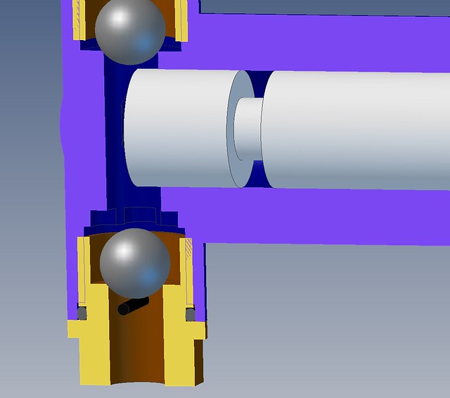 Pump inlet valve spring Pump inlet valve spring by Roger Froud, on Flickr |
|
|
|
Post by runner42 on Aug 29, 2018 8:25:01 GMT
Hi Roger,
it's a poppet valve and the O ring forms the seal when pressed against the seat. I find them easy to make and they are very forgiving in providing a perfect seal as opposed to the SS ball type which can be frustrating when the seat has some imperfection and leaks. I must admit your solution to prevent the ball sticking is very ingenious and doesn't need manual intervention, my solution to ball sticking is to have a tickler, which is a small piece of wire bent in a U at the end to lift it so it touches the ball to unstick it.
Brian
PS the tickler solution because it requires manual operation would not be as practical to use on a axle pump inside the frames of a locomotive, however it is someting I used on the emergency hand pump in the tender.
|
|
|
|
Post by Roger on Aug 29, 2018 8:58:18 GMT
Hi Roger, it's a poppet valve and the O ring forms the seal when pressed against the seat. I find them easy to make and they are very forgiving in providing a perfect seal as opposed to the SS ball type which can be frustrating when the seat has some imperfection and leaks. I must admit your solution to prevent the ball sticking is very ingenious and doesn't need manual intervention, my solution to ball sticking is to have a tickler, which is a small piece of wire bent in a U at the end to lift it so it touches the ball to unstick it. Brian PS the tickler solution because it requires manual operation would not be as practical to use on a axle pump inside the frames of a locomotive, however it is someting I used on the emergency hand pump in the tender. Hi Brian, I personally wouldn't use stainless steel balls anywhere as a valve now that Silicon Nitride ceramic balls are so cheap and readily available. I think they would overcome any objections you might have to using them in that position since they are much harder and have better geometric tolerances than most of the stainless steel balls used I model engineering. |
|
|
|
Post by runner42 on Sept 10, 2018 23:14:59 GMT
A modification to DY's Motion Plate Stay. I decided that bending 2.5 mm steel plate was not feasible mainly because 2.5 mm steel plate is not as available as 2 or 3 mm steel plate. So I used 3 mm and used similar fabrication techniques as the drag box. I however didn't follow the advice given in making the material thickness larger and machining to size after fabrication, I used the make the bits to size and hope for the best. The result is the important dimension 4 1/8" is 0.010" undersize. I will try and shim on assembly to the mainframes. When drilling fixing holes in say the motion plate, mainframes and motion plate stay (they all have to line up with the same screws) what is the best way to accomplish this? Brian  Motion Plate Stay Motion Plate Stay by Brian Leach, on Flickr |
|
Lisa
Statesman
 
Posts: 806 
|
Post by Lisa on Sept 11, 2018 1:06:03 GMT
If you do your drilling on the mill, you can scribble out a diagram; decide which hole is 0,0, and mark the dimensions, handwheel positions, and number of turns for each hole, that way they'll all match. This is how I did the steam chests, steam chest covers, and port face bolting holes on blowfly, and they all line up perfectly.
Alternatively, drill one part first, and use it as a jig for the others; again decide on a 0,0 hole, drill it in all the parts, bolt them together, and drill the rest.
|
|