|
|
Post by Deleted on Sept 11, 2018 7:49:17 GMT
Hi Brian
I'm no expert but believe that all structural holes should be drilled into the mainframes when bolted together before erecting. That's how Doncaster is done, full size too IIRC, you can then position the stay inside the frames, square it up and then transfer the holes. I have employed a variety of methods depending on the part and access to it. I find transferring a couple of holes, drilling and tapping these and then using them to hold the part in it's correct position while drilling the others works best for me. That's my preferred method but have used others when necessary, such as plotting one hole on the part if it's not something that can be squared up, ie cylinder block at an incline, and use that as my datum to plot the others directly from the frames.
regards
Pete
|
|
|
|
Post by runner42 on Sept 11, 2018 8:10:08 GMT
Thanks Pete and Lisa, most helpful replies. I think that drilling the mainframes bolted together is an essential prerequisite since the position of the motion plate on the frames is most important and at an angle to be normal to the cylinder bore. Once these holes are drilled using the milling machine for determining hole positions, these data can be repeated for drilling the motion plate and motion plate stay. If done correctly they all should line up.
Brian
|
|
|
|
Post by runner42 on Sept 14, 2018 8:17:14 GMT
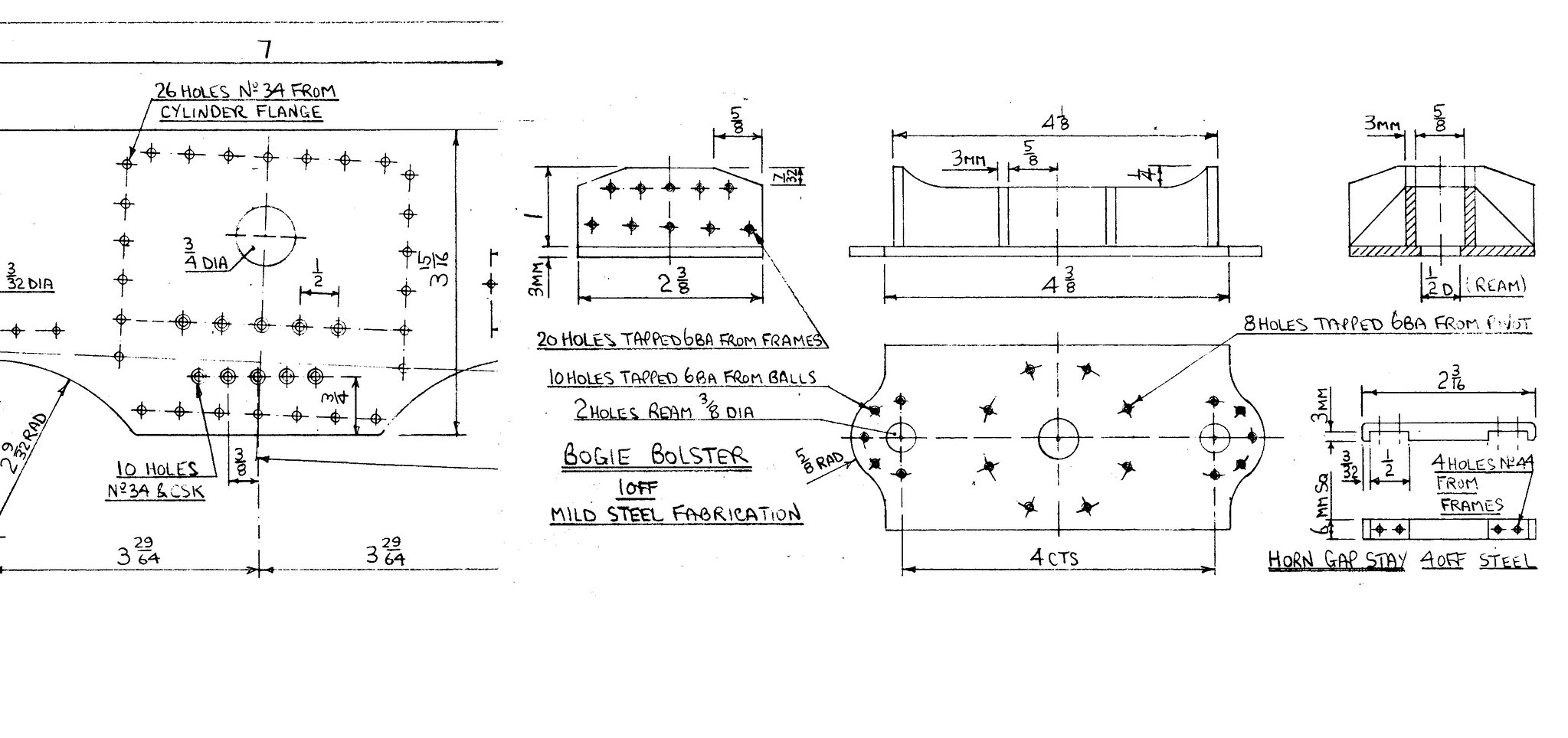
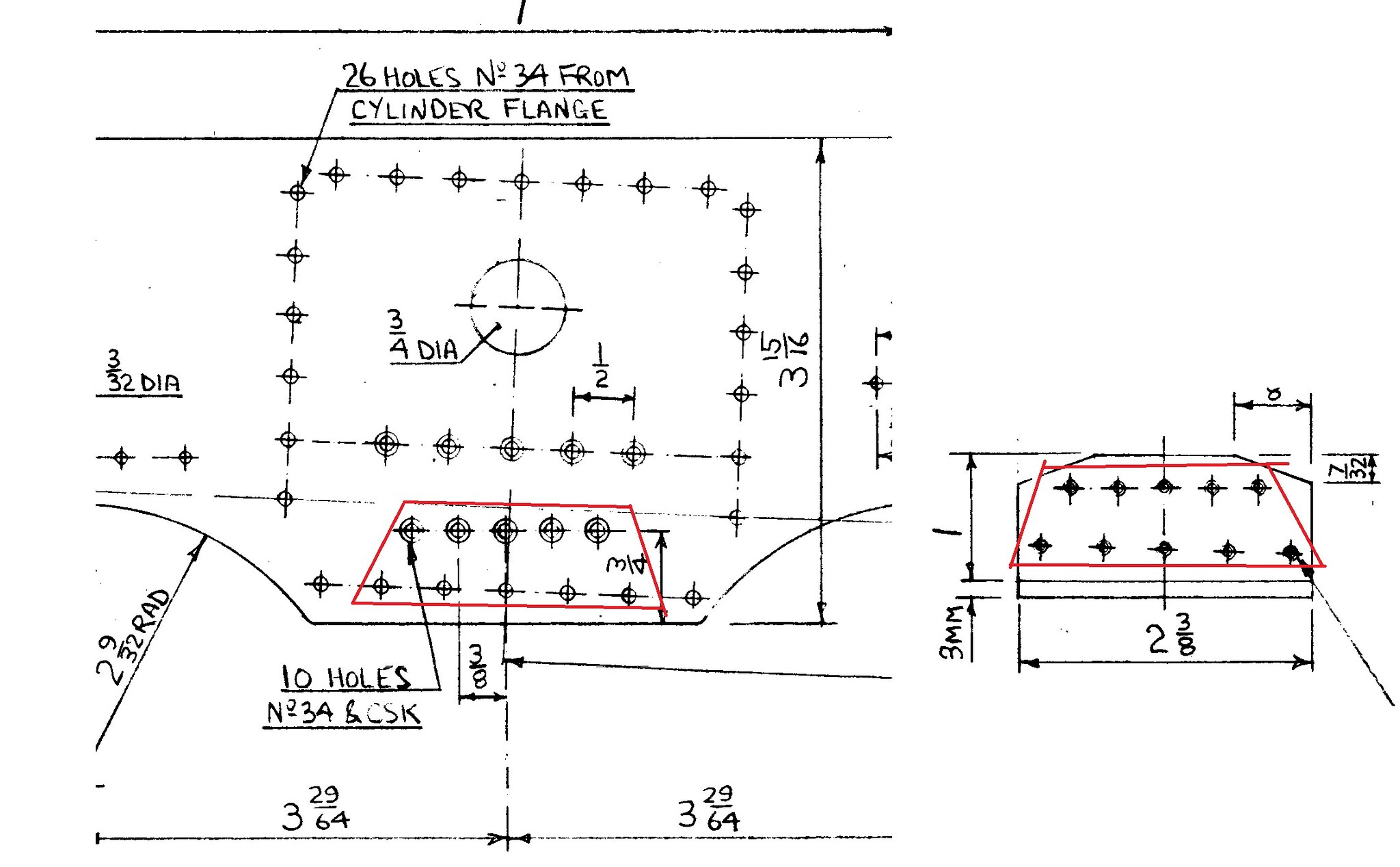
Started to drill the mainframe to bogie bolster and was once again flummoxed by DY's drawings. The bogie bolster 10 holes are in two rows of five, the top row is parallel to the mainframes and the bottom row is parallel to the cylinder centre line, the spacing of the top row is I assume 3/8" and the bottom row is again I assume 1/2". There doesn't appear to be a dimension for the spacing between the top and bottom rows. However, the problem is apparent because the mainframe detail shows that the spacing arrangement is inverted ie the top row is parallel to the cylinder centre line and the bottom row is parallel to the mainframes. In addition on the mainframe detail the bottom row is 3/4" above the mainframe bottom which is an irrational figure because the distance of the bolster above the bottom plate is only 1", so it does not compute. I would in other circumstances adopt an expedient approach and ignored the mainframe details and drilled the mainframe to suit the bogie bolster, but there is a lower set of holes which are the bottom row of the cylinder clamping plate. I don't want to forge ahead and adopt she'll be right approach and rue the fact that I didn't ask the "been there done that" Black 5 builders, what is the answer? All comments gratefully received. Brian  mainframe detail & bogie bolster mainframe detail & bogie bolster by Brian Leach, on Flickr |
|
stevep
Elder Statesman
  
Posts: 1,073
|
Post by stevep on Sept 14, 2018 8:36:20 GMT
Brian,
Reading your post, and looking at the drawing, I would think it's quite likely that the drawing is OK.
The top row of 5 holes, shown countersunk on the frame drawing, would match up fine with the bolster, which as you said, projects up 1". So plenty of room for the 6 BA tapped holes.
You mention the cylinder mounting plate in relation to the bottom set of holes, and that would also make sense - Don is using the bottom bolts of the plate to go right through the frame and screw into the bogie bolster.
The drawing of the cylinder mounting plates may give guidance on the spacing and position of the lower row of holes, which are probably marked off from the angled motion centre line.
|
|
|
|
Post by runner42 on Sept 14, 2018 8:59:24 GMT
|
|
|
|
Post by Deleted on Sept 14, 2018 9:03:14 GMT
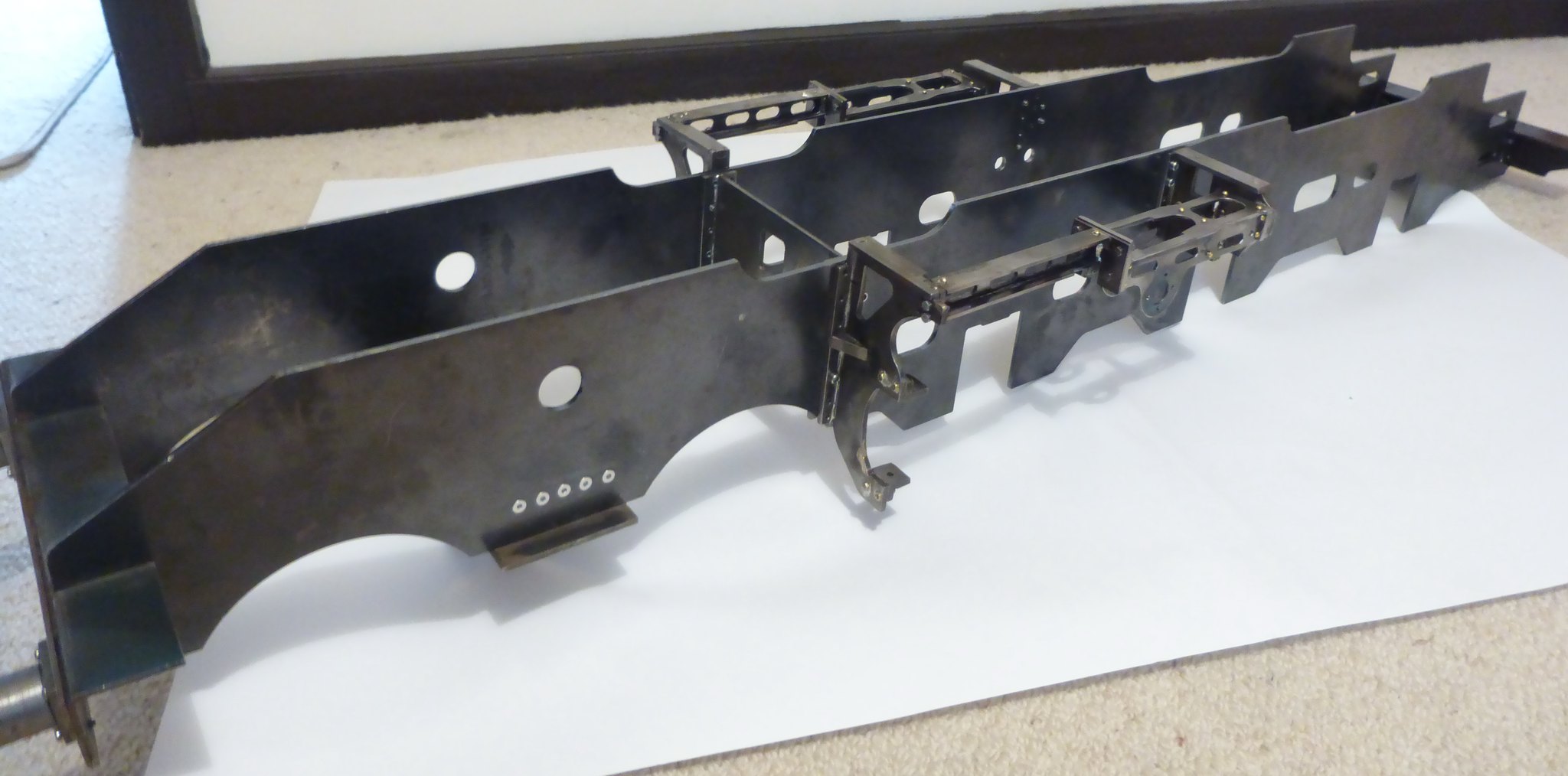
Hi Brian I agree with Steve, check the flange plate details for missing dimensions...to give you peace of mind here's an early picture to show that 'Doncaster' is the same re the lower cylinder flange plate holes also secure the bolster to the frame.. my outside cylinders are parallel though so a little less confusing.  regards Pete |
|
oldnorton
Statesman
  5" gauge LMS enthusiast
Posts: 726
Member is Online
|
Post by oldnorton on Sept 14, 2018 9:04:12 GMT
Hello Brian
Yes I agree that the sloping and the parallel to frame lines are tricky to interpret. I will try to explain how I worked through this and I do hope this might help in some way.
On the frames the 26 Holes No.34 form an outer rectangle *1 and these are the tapped holes that will secure the Cylinder Flange Plates. These flange plates can either pick up the drillings from the frames, or as Don says on the drawing "... No.34 FROM CYLINDER FLANGE". The cylinders then get their drillings from the flange plate inner holes.
The parallel to frame row of 5 holes "10 HOLES No.34 & CSK" are to secure the Bogie Bolster. Then, when the Cylinder Flange Plates are added (with Cylinders affixed) the lowest row of outer rectangle *1 holes are also tapped through to the Bolster permitting deeper attachment for the Flange Plate screws.
The innermost row of 5 holes immediately below the exhaust port are used to secure the Smoke Box Saddle. There is absolutely no reason at all why they follow the cylinder alignment, and this is what makes it confusing. In fact, I changed these holes to use just four each side that are spaced further out and around the exhaust port. I chose to do this to improve the sealing around the exhaust port by pulling the frames better onto the Smoke Box Saddle - the single row of screws at the bottom of the Saddle made no sense to me.
Beware the drawing of the Flange Plates at the top of Sheet 4 as my notes tell me it is not to scale in the vertical spacings and the "1 11/32" might be wrong (I have crossed it through). I redrew it to agree with the frame drillings.
I do suggest that you get a set of the final drawings from Reeves (with stencil text) just in case there are changes from your early hand scripted set.
Best wishes
Norm
|
|
|
|
Post by Deleted on Sept 14, 2018 9:07:49 GMT
You're looking at the wrong holes Brian, the bolster sits along the bottom edge of the frames, the 3mm lip being the stop so to speak...ignore the top row of holes in your red box on the frames, look at the lower holes at the bottom of the frames, these will match those in the bolster....unless that is, I'm not thinking straight this morning...  Pete I should add, the central 5 bottom holes match the bolster, the outer two must be for the flange plate alone... |
|
|
|
Post by simplyloco on Sept 14, 2018 9:10:21 GMT
You're looking at the wrong holes Brian, the bolster sits along the bottom edge of the frames, the 3mm lip being the stop so to speak...ignore the top row of holes in your red box on the frames, look at the lower holes at the bottom of the frames, these will match those in the bolster....unless that is, I'm not thinking straight this morning...  Pete I'd be wary of ANY drawing that mixes imperial with metric, as that one does! John |
|
|
|
Post by Deleted on Sept 14, 2018 9:13:20 GMT
You're looking at the wrong holes Brian, the bolster sits along the bottom edge of the frames, the 3mm lip being the stop so to speak...ignore the top row of holes in your red box on the frames, look at the lower holes at the bottom of the frames, these will match those in the bolster....unless that is, I'm not thinking straight this morning...  Pete I'd be wary of ANY drawing that mixes imperial with metric, as that one does! John IIRC John, Don does this when specifying the closest available stock size for the job in hand, perhaps 3mm is closer (more suitable) to scale than 1/8th? Pete |
|
|
|
Post by simplyloco on Sept 14, 2018 13:07:26 GMT
Pete, I wish (sometimes) that I had your generous nature!  John |
|
|
|
Post by Deleted on Sept 14, 2018 13:11:45 GMT
Pete, I wish (sometimes) that I had your generous nature!  John haha..no but honestly, Don often states in his words that he chooses material (metric or imperial) by what's closest to scale and what's stocked by Reeves, in some cases, Reeves especially take stock of a suitably sized material to suit Don's drawings. Pete |
|
|
|
Post by runner42 on Sept 14, 2018 21:40:36 GMT
Thanks for the replies, but Norm's and Pete's explanation cracked it for me, here's the answer, Brian  the answer the answer by Brian Leach, on Flickr |
|
dscott
Elder Statesman
  
Posts: 2,440
|
Post by dscott on Sept 14, 2018 23:20:42 GMT
I would or WILL just drill the bottom 5 holes clearance and tap the
5 holes in the 3mm plate of the Bolster as nuts are usually this thick
and it saves time and makes alignment easier!
Had this bit out on the dining table last week?
We sit in front of the box and mouse something in from You Tube!!!
Keith Appleton at the moment!! Love the dining table for drawings!!!
David and Lily.
|
|
|
|
Post by runner42 on Sept 15, 2018 22:07:50 GMT
Thanks David and Lily,
however I did the reverse. I have only drilled and tapped the top five holes in the bogie bolster with clearance holes in the frame. The reason being I am a long way from fitting the cylinder plates and when at that stage I will use the drilled cylinder plate as the drilling guide.
Brian
|
|
|
|
Post by runner42 on Sept 17, 2018 7:36:59 GMT
Deleted
|
|
|
|
Post by runner42 on Sept 24, 2018 7:39:39 GMT
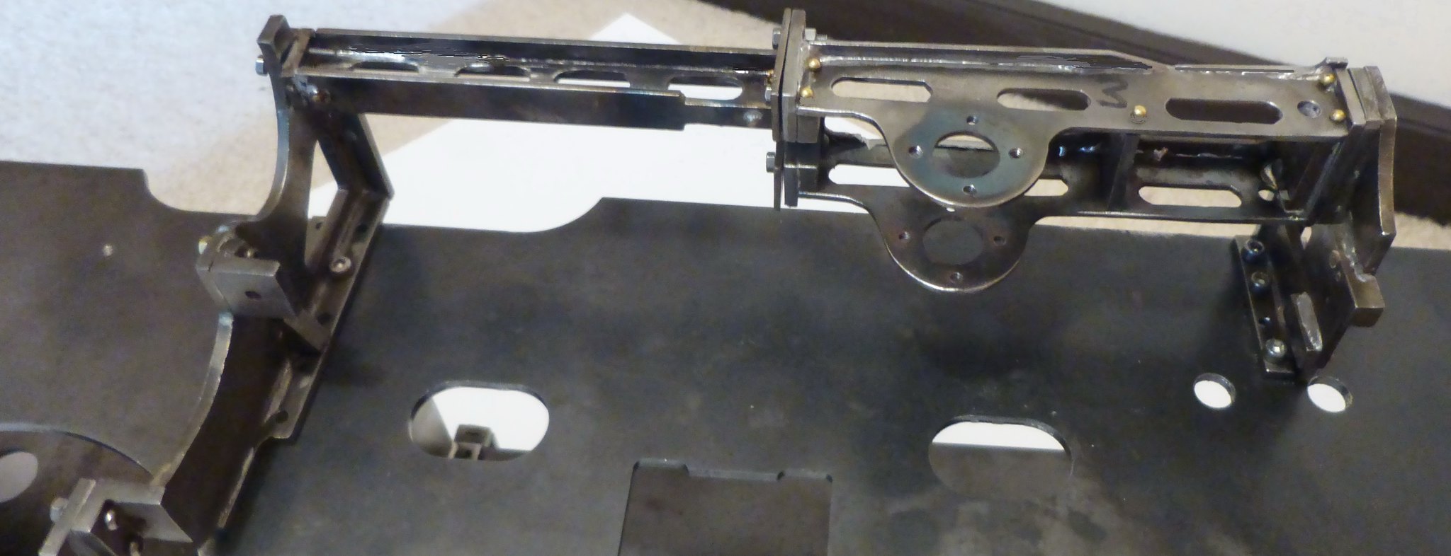
A small update prior to catching the big bird and flying to Venice to set sail on a cruise liner to various places on the eastern seaboard of the Adriatic and on to the Mediterranean for visits to Malta Sicily and Rome. Another stopover on the return journey to Adelaide. I re-visited Pete's (Greenglade) to see how he tackled drilling the frames. It appears that it was an iterative process of assembling and stripping the chassis as and when each new part was installed so that the frames could be drilled together. I have other parts that need frame drilling but that will have to wait until I return. I expect SWMBO will ask on the cruise what are you thinking about, not that train again and I reply it's not a train it's a locomotive. Brian  P1030661 P1030661 by Brian Leach, on Flickr  P1030662 P1030662 by Brian Leach, on Flickr  P1030663 P1030663 by Brian Leach, on Flickr |
|
Neale
Part of the e-furniture
 5" Black 5 just started
Posts: 283 
|
Post by Neale on Oct 13, 2018 9:12:04 GMT
I'm making slow progress on my own DY Black 5, currently working on tender drag boxes. Didn't fancy DY's words and music - "cut pieces to size, hold together with temporary bolts into tapped holes in edges of plates, horizontal pieces will jam in place while silver-soldering". My favourite phrase "what could possibly go wrong?" comes to mind...
Toyed with the idea of buying laser-cut parts but not sure if those available off-the-shelf are compatible with DY frames (which I have from Reeves) or to another design. So, drew up the drag box in F360, and modified all the bits for tab-and-slot assembly. Managed to cut all the bits on my CNC router (wasn't sure it would be up to it, but did a better job than expected). Bit of work with files and it all goes together very nicely.
Question now is - do I silver-solder or run beads of MIG weld down the joints? I have made parts slightly oversize with the intention of machining to dimension afterwards so minor distortion is acceptable. However, I do not remember ever seeing anyone talk about welding components like this - is there a good reason for this?
As a follow-up, how were the full-size parts made - castings, welded fabrications, or what? I'm thinking here about tidying up joints between the individual panels - for example silver-solder would give a much smaller fillet than welding.
I'm about to go the the workshop to run some test welds on offcuts of the steel I'm using but interested to hear comments.
|
|
|
|
Post by steamer5 on Oct 13, 2018 17:42:11 GMT
Hi Neale,
Would love to see some pictures of how you are doing this if possible? I had a friend weld up my stretches, he did a great job. He put the side plates against the frame so they just overlapped & welded up. I then dressed the weld to give a nice radius to make it look like the original, which had the stretches folded. The problem was I hadn’t allowed for any machining! So now I need to make another set!
Brian,
Looking good!
Cheers Kerrin
|
|
|
|
Post by Roger on Oct 13, 2018 18:29:51 GMT
I'm making slow progress on my own DY Black 5, currently working on tender drag boxes. Didn't fancy DY's words and music - "cut pieces to size, hold together with temporary bolts into tapped holes in edges of plates, horizontal pieces will jam in place while silver-soldering". My favourite phrase "what could possibly go wrong?" comes to mind... Toyed with the idea of buying laser-cut parts but not sure if those available off-the-shelf are compatible with DY frames (which I have from Reeves) or to another design. So, drew up the drag box in F360, and modified all the bits for tab-and-slot assembly. Managed to cut all the bits on my CNC router (wasn't sure it would be up to it, but did a better job than expected). Bit of work with files and it all goes together very nicely. Question now is - do I silver-solder or run beads of MIG weld down the joints? I have made parts slightly oversize with the intention of machining to dimension afterwards so minor distortion is acceptable. However, I do not remember ever seeing anyone talk about welding components like this - is there a good reason for this? As a follow-up, how were the full-size parts made - castings, welded fabrications, or what? I'm thinking here about tidying up joints between the individual panels - for example silver-solder would give a much smaller fillet than welding. I'm about to go the the workshop to run some test welds on offcuts of the steel I'm using but interested to hear comments. Hi Neale, Personally, I'd tack weld it together with the smallest of tacks, and then Silver Solder it. That's what I do with the TIG welder and it works really well. You get it held really firmly, and you can straighten it up when it's all together. Then Silver Soldering can be done without any further worries. I'd drown the whole thing in flux when you do that so that there's as little cleaning up of the dreaded black oxide as possible. |
|