Neale
Part of the e-furniture
 5" Black 5 just started
Posts: 283 
|
Post by Neale on Oct 13, 2018 20:16:22 GMT
Couple of screen grabs from Fusion 360 to show the structure. I modified/improved my technique with almost every piece I cut. I eventually (after spending quite a bit of time with needle files squaring out the corners of slots and the bases of tabs) realised that location is entirely on the flat surfaces of the tabs and the rest of the structure constrains sideways movement, so tabs do not need to be a close fit side-to-side in slots. So I ended up making the slots very slightly overlong and rounding the ends, and cutting semicircular bites out of the base of the tabs to give clearance. Makes fitting much quicker and easier - you can see some of this in the exploded view. What it is supposed to look like when finished: 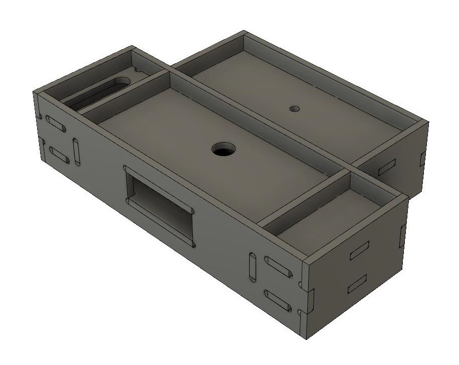 And an exploded view. This was created by F360 but due to the fact that I had several pieces forming one component, and F360 explodes at the component level, this needs just a little bit of study to see how the bits fit.  Looking at the image, I see that the "explosion" has left some debris in the wrong place. The double-piece vertical pieces should be inside the single piece and not outside. Comparison with the "what it's supposed to look like" image should make it clearer. I decided to weld it fully (remember - "What could possibly go wrong?") and the assembly is now clamped to the bed of the mill for finish machining. Picture of item to follow - my welding is absolutely dreadful although I did do a few practice runs first. However, my CNC router is all welded steel, and although the welding on that is dreadful as well, it holds together well enough to have been able to machine these steel bits for the model. Grinder and JB Weld are called for and once painted, and given that none of this will be visible once the thing is on the track, I'm not losing sleep over it. I shall probably weld the rear drag box the same way, but the intermediate stretchers will be silver-soldered. The idea of a few strategic tack welds is useful - I'll certainly consider that although I do have ideas on how I can tab-and-slot those as well. |
|
Neale
Part of the e-furniture
5" Black 5 just started
Posts: 283
|
Post by Neale on Oct 13, 2018 22:02:27 GMT
Now, promise you won't laugh... Some of the welding is diabolical. The rest isn't up to that standard (where's the red face smiley when you want one?)  However, I think that there is sufficient weld in sufficient places and with sufficient penetration that there is adequate strength. The coupling pin bushes were spigoted and welded into the appropriate plates before welding up the full structure. After welding, I cleaned up one "face" so that the box sat without rocking on the milling machine table and took a light skim off the top. Then I flipped it and machined the other face to bring the thing to size. Reclamped with the buffer beam face parallel (to a reasonable approximation as it was not quite flat) to the X axis and took a skim off that with the side of a big end mill. At the same setting, I machined the frame bolting faces to clean up and bring the overall width to size. I still need to drill and ream the coupling pin hole. The image shows the box clamped between the tender frames; I wanted to reassure myself that having done so, the frames didn't point off at funny angles. To my great relief, they do not. I still reckon that a grinding point in a Dremel plus JB Weld will make it look perfect. At least to a "Your friends will never know the difference" standard  And a quick question for the experts - will citric acid clean up the oxidation from the welding? |
|
|
|
Post by Roger on Oct 13, 2018 22:53:20 GMT
Hi Neame,
Personally, I wouldn't use Citric acid on any ferrous materials. It happily dissolves unprotected metal as well as the oxidised places.
|
|
|
|
Post by steamer5 on Oct 15, 2018 0:01:57 GMT
Hi Neale,
Thanks for the screen shots & explanation. Makes things much clearer!
As to the welding.........it’s way better than mine!
Cheers Kerrin
|
|
|
|
Post by runner42 on Oct 18, 2018 7:18:00 GMT
I am stuck on understanding the bogie and how each piece fits together. I have searched the web for photos of this assembly but to no avail. I would be grateful if a photo of the completed bogie is posted.
Brian
|
|
|
|
Post by Deleted on Oct 18, 2018 7:56:49 GMT
Hi Brian
I failed to find a picture too...perhaps we can help if you post the drawing with any questions? I know other members have built this model yet can't find anything re the bogie ....
kind regards
Pete
|
|
|
|
Post by Deleted on Oct 18, 2018 8:06:07 GMT
Hi Brian I tried another search and found this thread which discusses the bogie in some detail, in particular, possible fouling issues with the beams... there's also 2x 3D CAD drawings of the bogie on page 2...hope this helps.. modeleng.proboards.com/thread/1266/don-youngs-black-5Pete |
|
|
|
Post by runner42 on Oct 18, 2018 23:20:40 GMT
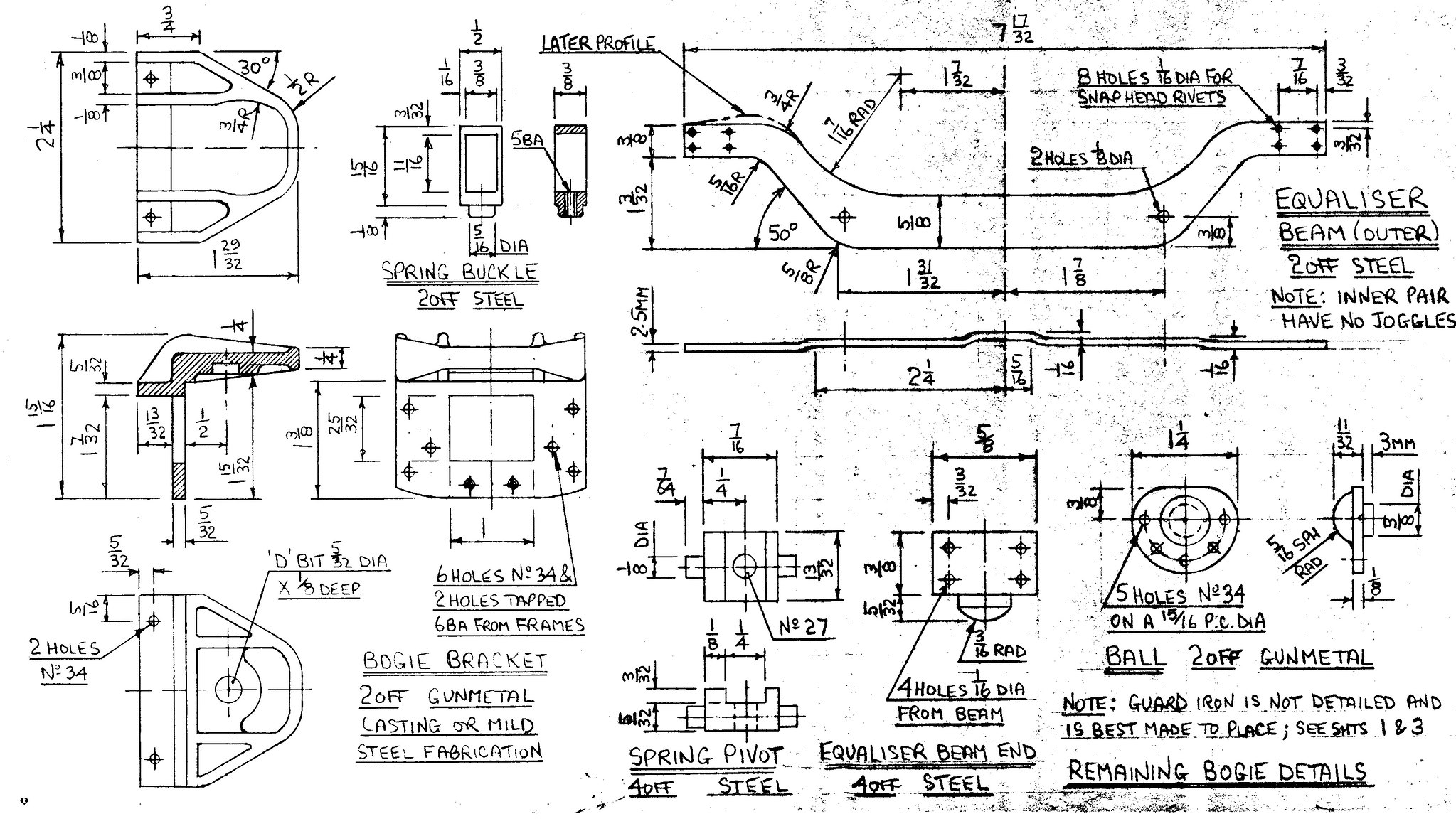
Thanks Pete, you are constantly answering my concerns for which I am most grateful. The link you provided displaying the 3D picture does answer some of my concerns, however the main concern lies with the centre part which is unnamed and is probably the yellow coloured item in the 3 D picture. It doesn't appear to have the 3rd dimension specified, is it that it occupies the gap between the bogie half centres? Also the gunmetal buffer appears to be fixed in the centre of the unnamed part, but the two parts have incompatible dimensions. Brian  whats this whats this by Brian Leach, on Flickr |
|
|
|
Post by Deleted on Oct 18, 2018 23:40:53 GMT
Hi Brian
can you show the rest of the drawing including dimensions please, I may be able to understand it a little more.
I'm off to bed in a few mins so may not see it till tomorrow....
regards
Pete
|
|
|
|
Post by runner42 on Oct 19, 2018 6:47:15 GMT
|
|
Lisa
Statesman
Posts: 806 
|
Post by Lisa on Oct 19, 2018 8:14:12 GMT
If it comes to it Brian, maybe make all the bits from cardboard then try to work out how they fit together like a box of Lego with no instructions.
|
|
|
|
Post by Deleted on Oct 19, 2018 9:11:39 GMT
Hi Brian
That's an interesting bogie, lots going on and I can see why it's a little confusing...I haven't fully digested it's workings, I think like Lisa i'd make up the parts and see how they fit although myself I'd trust Don's design in that everything will fit once assembled and make from metal.
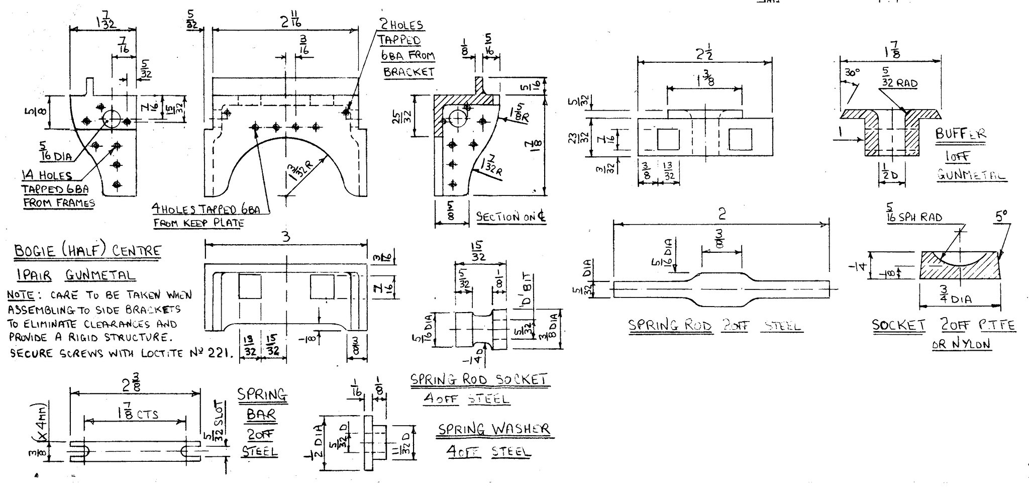
Now looking at the drawing you showed first of the buffer, at first I thought this was showing two parts with the buffer itself being a 'turned' item but now that I can see the rest and can cross check dimensions this looks to be two views of the same part, for want of a better word, a spacer between the two 'bogie center's', buffer makes one think of something 'round'. The drawing of the 'keeps' as seen in the 'bogie arrangement' drawing would help to confirm this (can't see it in the drawings posted). The buffer (spacer) is of rectangular shape sandwiched between the 'center's. The flange on the top face having a squared side along it's length but angled 30 degree's along it's width for the 'keeps' to locate in place. As stated i haven't fully digested the design but think this may answer your question. I note that Abby who did the CAD work was online just a couple of days ago so perhaps a PM to him might confirm what I'm thinking?
hope this helps, more importantly, hope I read this right... I'll try to digest it a little more later to confirm
NB: the width of the 'buffer's' lower part seems to suggest '1 inch' that looks right when looking at the drawing itself, ie 1/2" pivot hole with assumingly 1/4 either side.
|
|
stevep
Elder Statesman

Posts: 1,073
|
Post by stevep on Oct 20, 2018 8:47:31 GMT
I agree with this. I also thought it was a round part, but it makes far more sense as you have described. If we had the third projection, it would have all been clear!
|
|
|
|
Post by runner42 on Oct 20, 2018 22:12:42 GMT
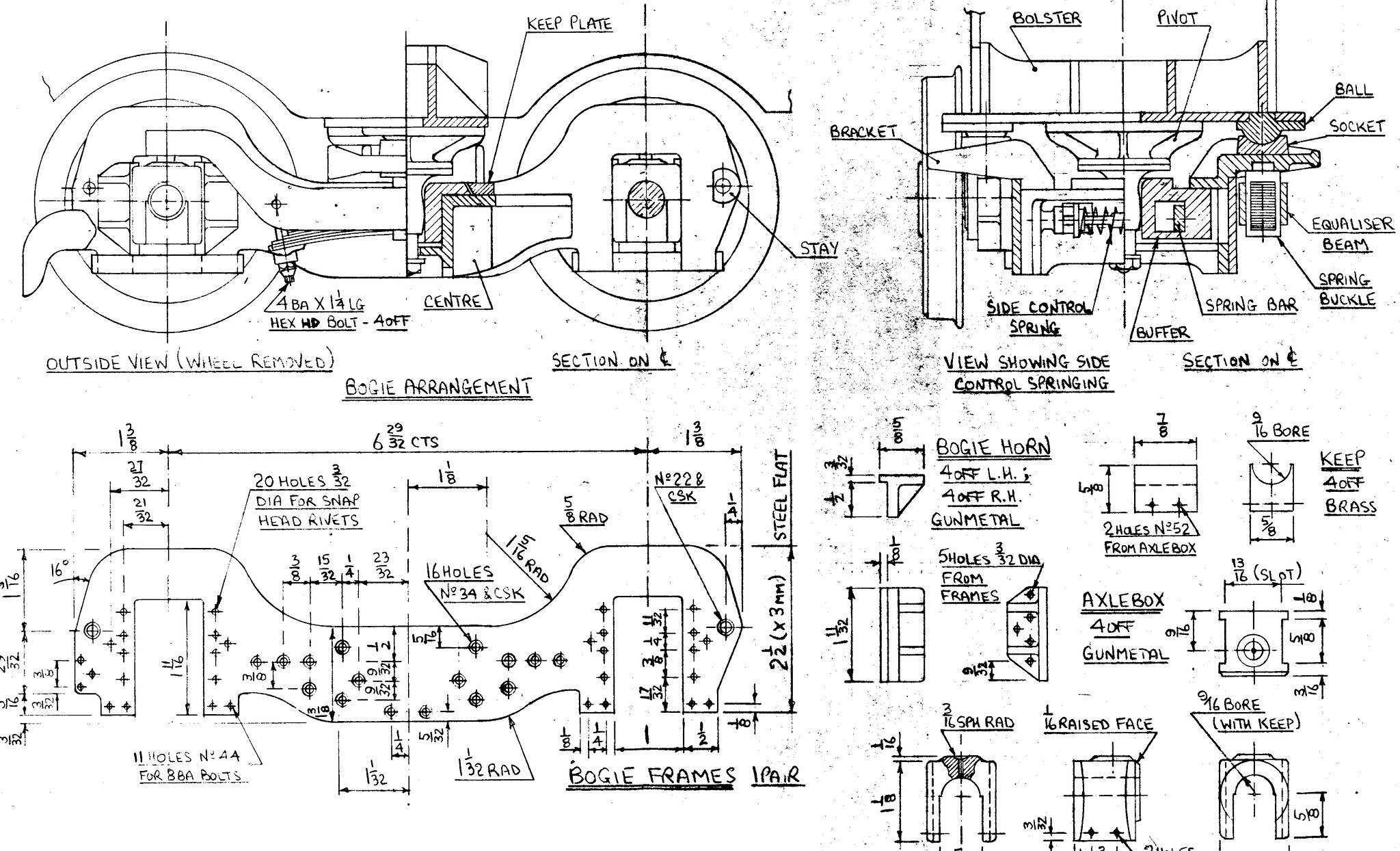
Thanks Pete and Steve, so the buffer is not circular at the top but rectangular being 1 7/8" X 1 3/8" with a 30 deg chamfer on the 1 7/8" dimension only, but where is that elusive keep plate shown in the bogie arrangement drawing?
Brian
|
|
|
|
Post by Deleted on Oct 20, 2018 22:23:28 GMT
Hi Brian..
Err..no....going back to your original post showing the buffer and I think what you called the 'unknown' part...those two drawings are in fact two views of the same part. As Steve said...if the 3rd view ( the plan view as I was taught in TD) had been included this would have been much clearer.
Hope that explains it better...cheers
Pete
|
|
uuu
Elder Statesman
your message here...
Posts: 2,860
Member is Online
|
Post by uuu on Oct 21, 2018 7:37:17 GMT
This also explains why, in the middle of the three pages, the view showing side control springing, the part labelled "Buffer" is just one piece, not two.
Wilf
|
|
|
|
Post by runner42 on Oct 21, 2018 7:46:13 GMT
A picture saves a thousand words, so is this it? I assume that the cross hatching on the buffer indicates that it is a sectioned view so I have assumed that this view is half the complete item. Because of the lack of third projection is a best guess result but I could be way off. Brian  Buffer Buffer by Brian Leach, on Flickr |
|
|
|
Post by Deleted on Oct 21, 2018 7:55:49 GMT
Yes it's a cross section half way through...your isometric view looks right to my eye....mind you I'm still in bed a little blurry eyed....well it is Sunday.... Pete |
|
stevep
Elder Statesman
Posts: 1,073
|
Post by stevep on Oct 21, 2018 9:02:00 GMT
I was going to do the same thing Brian. I think you've got it. The raised part with the chamfer is 11/16" long in your half-section (1 3/8" all together).
|
|
|
|
Post by runner42 on Oct 26, 2018 6:40:09 GMT
Made a start on the bogie and I have by necessity had to change DY's design, due mainly to not having ME stockist in the Antipodes supplying bar gunmetal for the buffer and simplifying the design of the half centres. Assuming the only bearing surface is the centre of the buffer I made that from gunmetal. Also the essential castings such as wheels and cylinders does not appear to be available from EJ Winter any longer, I assume that he is rationalising his stocks and only keeping the ones that are more in demand. So I would like to know where I can get these. Brian 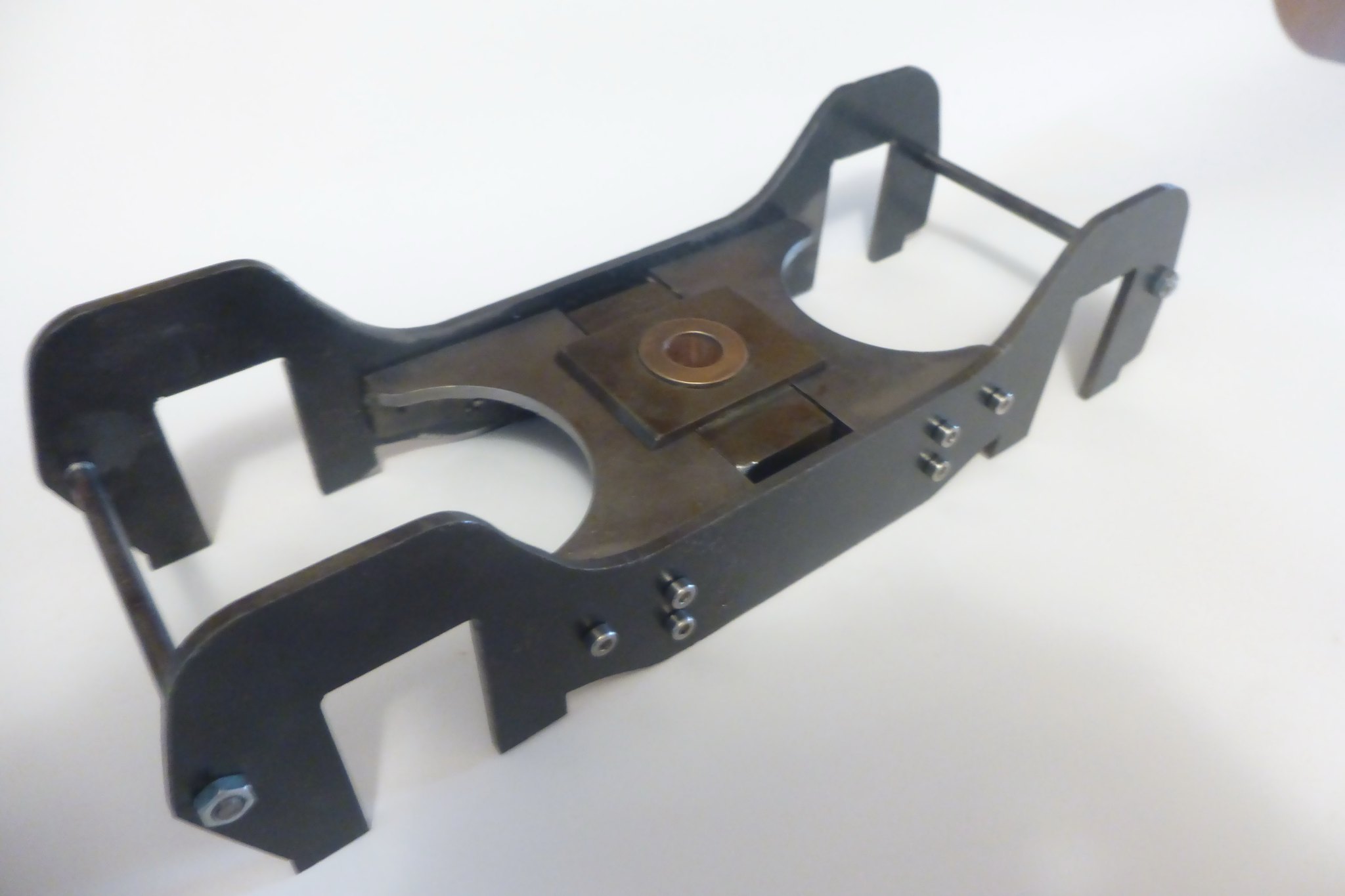 bogie assy bogie assy by Brian Leach, on Flickr |
|