Lisa
Statesman
 
Posts: 806 
|
Post by Lisa on Oct 26, 2018 7:28:52 GMT
If you need flat/square/rectangular bar sections of cast iron or bronze, ask about axlebox 'sticks'; there's a lot of different sizes for various designs, so you can often get bar that way provided you don't need more than 6-12" lengths.
|
|
|
|
Post by runner42 on Oct 27, 2018 6:36:59 GMT
How does the side control spring work, if I can understand it's operation then the assembly of those parts of the bogie may become clearer?
Brian
|
|
|
|
Post by Jim on Oct 27, 2018 21:14:13 GMT
The side control springs are located each side of the pivot block and as I understand it assist the bogie in guiding the loco through curves and returning it to a central position once on the straight. Similar springs exist on the trailing truck of the Britannia but in the Perrier drawings the springs are mounted on a straight rod which I believe should be curved to the same arc the truck swings to as it moves through a curve.
Jim.
|
|
|
|
Post by Deleted on Oct 27, 2018 22:44:13 GMT
Hi Brian
Sorry I meant to answer your question last night but forgot and have been out all day at my grandson's 4th birthday party..I've taken a closer look and think that I have the design clearer in my head so will try to answer your question. As you will be aware the buffer slides from side to side between the center halves. Parts involved for the side control itself are the springs, spring washers, spring rods, spring rod socket and spring bar. These make up two spring sections, one front and one rear of the bogie center halves. Note that the center halves have 5/16 holes in them, this is to locate the sockets which sit either end of each spring assembly. The spring rods fit between the sockets either side, then the washers and then springs. note that both the buffer and center halves have square cutouts, these are to allow the spring bars to pass through both buffer and center halves with the forked ends slipping over the spring bar between sockets and spring washers...Hopefully, my poor description might make the spring control drawing a little clearer?
Kind Regards
Pete
|
|
|
|
Post by runner42 on Oct 28, 2018 6:40:16 GMT
Thanks Pete and Jim. LBSC in his Doris construction did not require a side control spring but indicated that such an arrangement was required if one scaled up his Doris design to 5" gauge. Is the spring working in compression or tension mode, ie is it being lengthened or shortened? I think that looking at a simplified arrangement as shown that the spring is being lengthened when buffer is being moved laterally in one direction due to the curvature of the track and this lengthening tends to resist further movement and causes it to return to its original position. There is obviously a limit on the lateral movement that the buffer can achieve due to the size of the rectangular cut-outs. I assume that this arrangement tends to dampen the movement. Brian 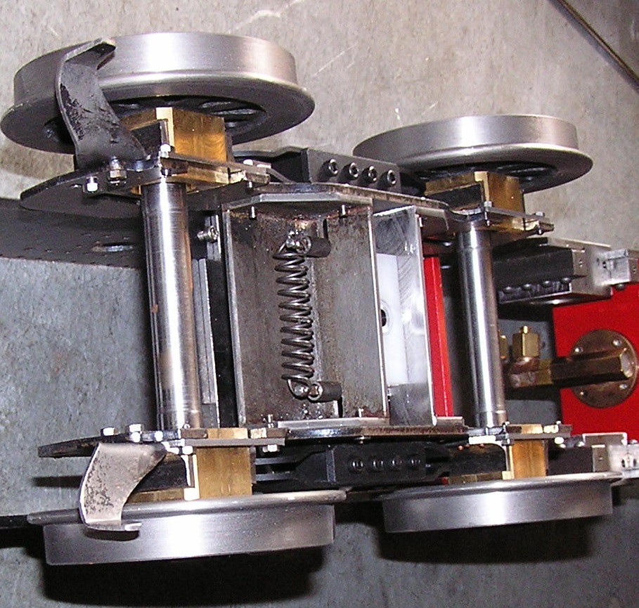 simple bogie simple bogie by Brian Leach, on Flickr |
|
|
|
Post by runner42 on Oct 30, 2018 6:29:33 GMT
Thanks Pete and Jim. LBSC in his Doris construction did not require a side control spring but indicated that such an arrangement was required if one scaled up his Doris design to 5" gauge. Is the spring working in compression or tension mode, ie is it being lengthened or shortened? I think that looking at a simplified arrangement as shown that the spring is being lengthened when buffer is being moved laterally in one direction due to the curvature of the track and this lengthening tends to resist further movement and causes it to return to its original position. There is obviously a limit on the lateral movement that the buffer can achieve due to the size of the rectangular cut-outs. I assume that this arrangement tends to dampen the movement. Brian  simple bogie simple bogie by Brian Leach, on Flickr I had a 50/50 chance of getting it right, however I got it wrong. Having constructed the side control spring mechanism it's painfully obvious that the springs are being compressed. The well informed MEs out there didn't attempt to correct me assuming I would find out my error in due course. Brian PS looking again at the picture the spring bars are at the inside of the slot so the only movement possible is the lengthening of the spring as one or other of the bars move to the outside position. However, the spring bars in DY's design are at the outside position and move towards the centre when the buffer is moved. So different strokes for different blokes. |
|
|
|
Post by chris vine on Oct 30, 2018 9:47:31 GMT
Hi Brian,
I think you were right first time, if I understood you correctly.
The springs look as though they will be stretched, in tension, as the bogie is pushed to the side.
Also, by the arrangement of slots, there will be a snapping action to the centre. This means that there can be some preload on the springs, so that as soon as the bogie is pushed off centre, there is a decent side force.
If you just have a spring pushing towards the centre, the load only builds up slowly with displacement.
Chris.
|
|
|
|
Post by runner42 on Oct 31, 2018 0:51:11 GMT
Hi Brian, I think you were right first time, if I understood you correctly. The springs look as though they will be stretched, in tension, as the bogie is pushed to the side. Also, by the arrangement of slots, there will be a snapping action to the centre. This means that there can be some preload on the springs, so that as soon as the bogie is pushed off centre, there is a decent side force. If you just have a spring pushing towards the centre, the load only builds up slowly with displacement. Chris. Hi Chris, yes the example shown in the picture the spring is in tension, but if you look at DY's drawing for the bogie arrangement view showing side springing arrangement the spring bars are positioned at the outside positions of the cut-out so the only movement is towards to centre thus putting the spring under compression. Brian |
|
|
|
Post by runner42 on Nov 1, 2018 5:16:07 GMT
A bit more added to the bogie and the side control spring arrangement not to the letter of DY's requirements but at least in the spirit of his design. I jammed a bit of wood at the side of the buffer to show the side control springs under compression. Brian 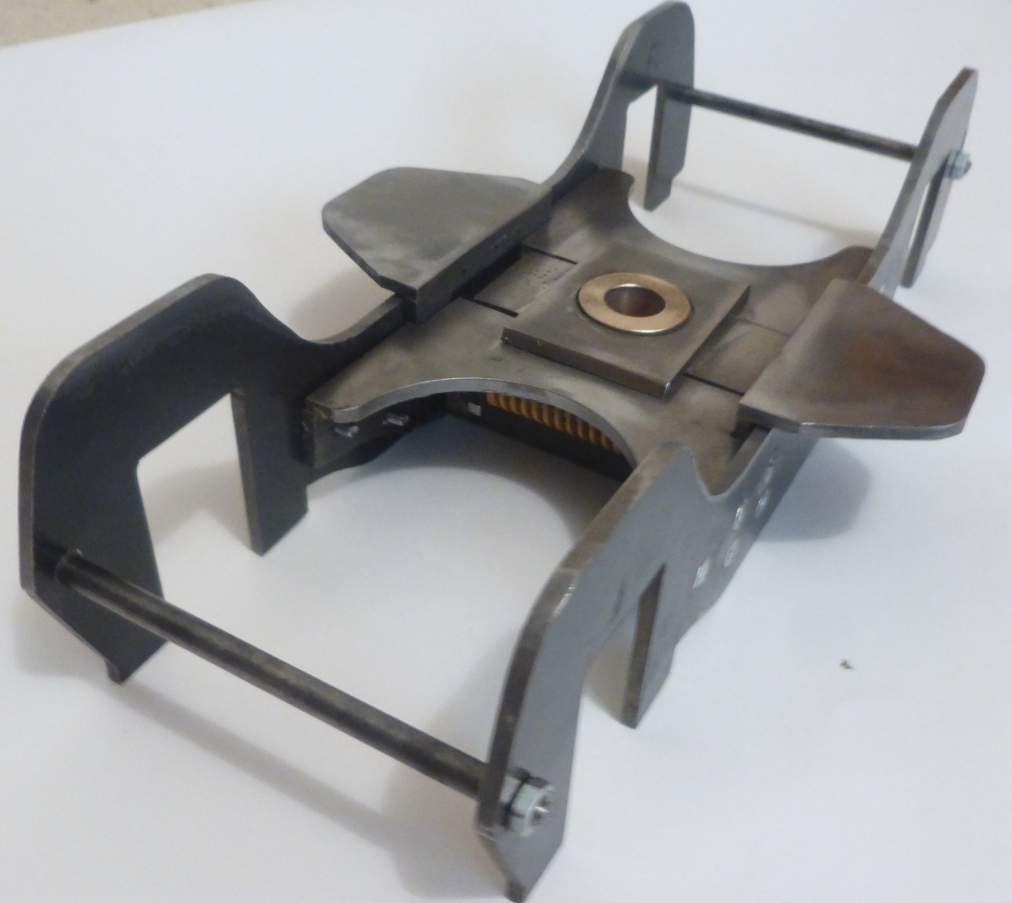 P1040154 P1040154 by Brian Leach, on Flickr 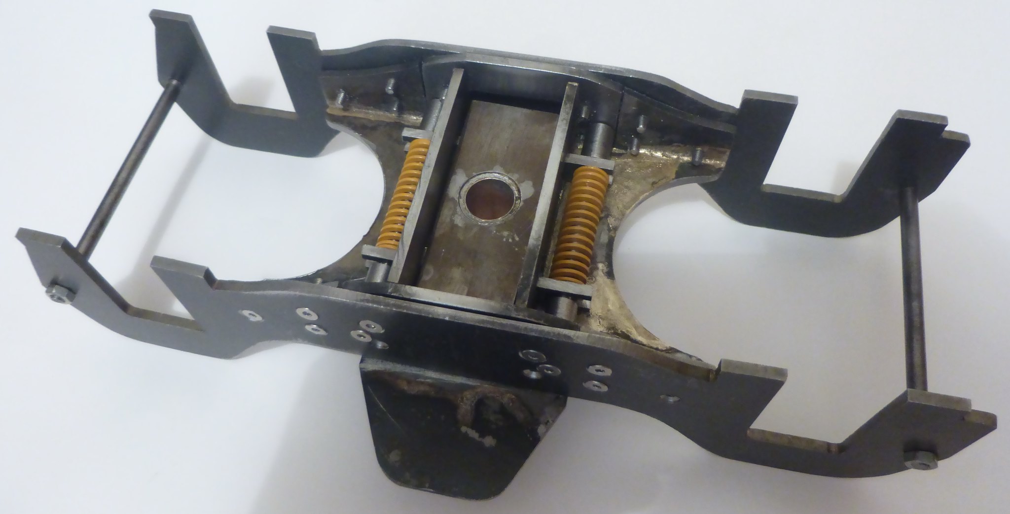 P1040156 P1040156 by Brian Leach, on Flickr 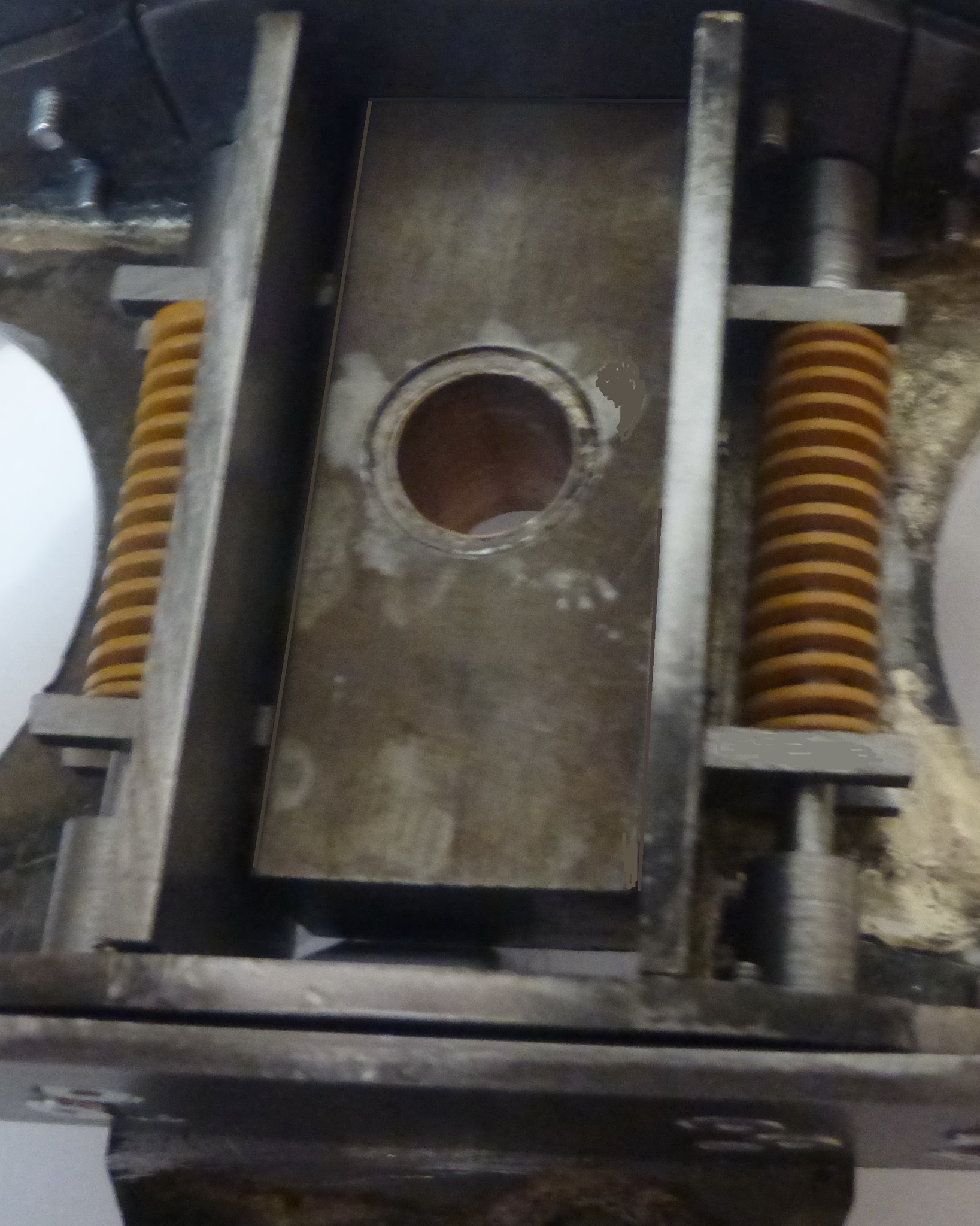 P1040158 P1040158 by Brian Leach, on Flickr |
|
|
|
Post by runner42 on Nov 3, 2018 4:38:04 GMT
A bit more on the bogie, the pivot added. My digital camera is crap for taking close up photos is very poor it has a macro setting but this is not available for ordinary photos..strange. Brian 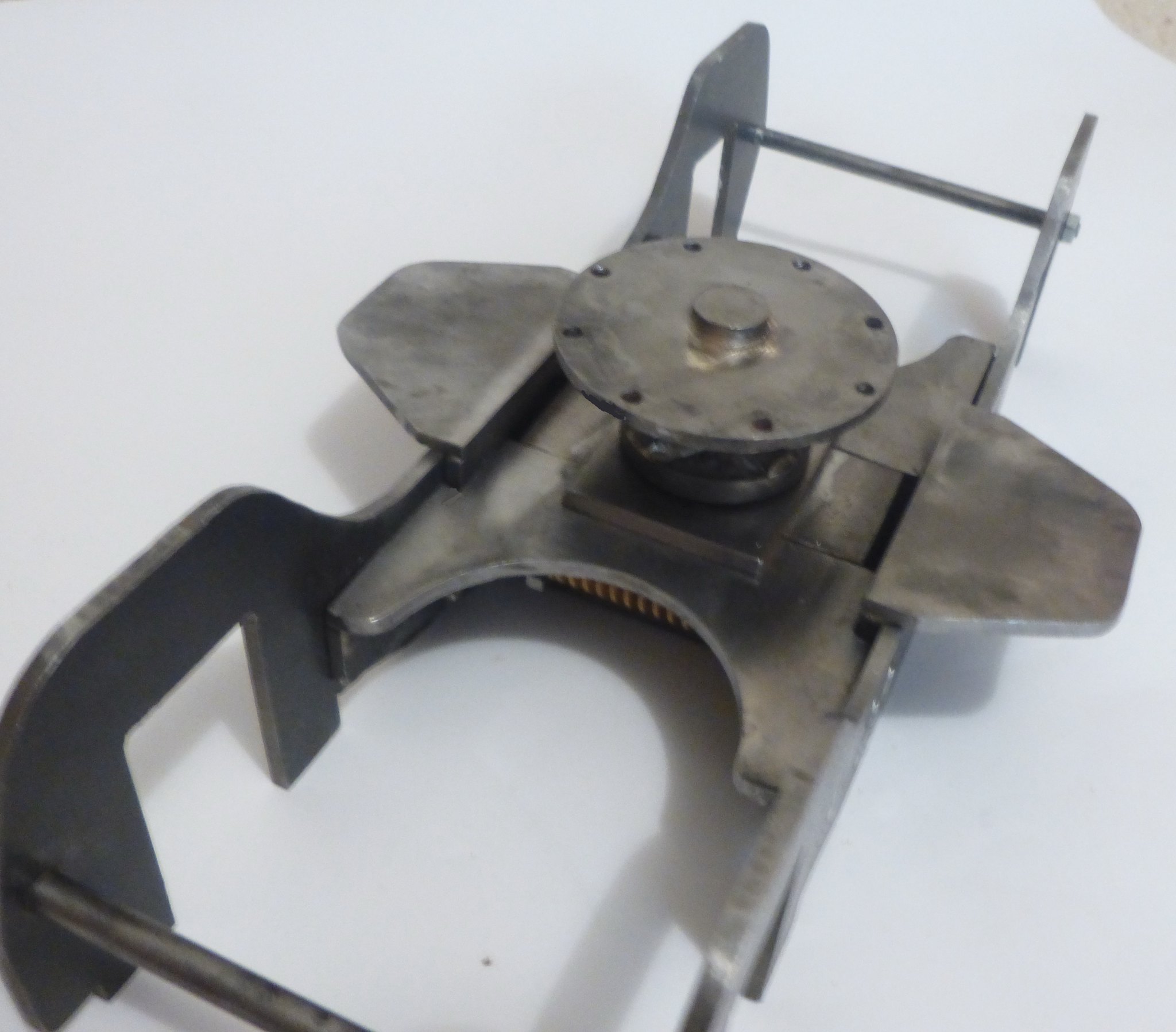 P1040160 P1040160 by Brian Leach, on Flickr 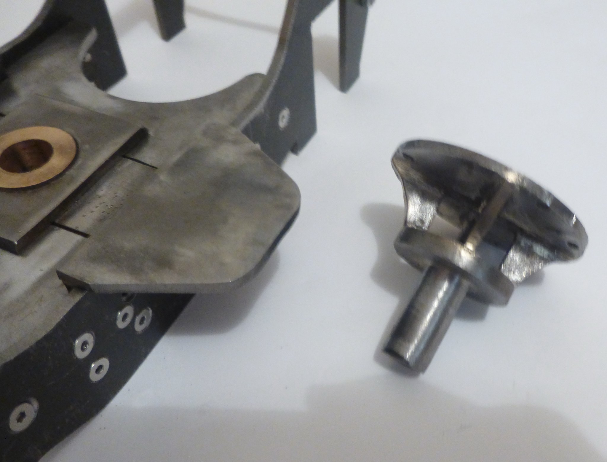 P1040161 P1040161 by Brian Leach, on Flickr |
|
|
|
Post by runner42 on Nov 12, 2018 6:53:36 GMT
A bit more added to the bogie. I am delayed by not receiving items I ordered from E J Winter three weeks ago namely the bogie wheels, gunmetal stick for the bearings and brass angle for the horn cheeks. These were requested using the order form sent to the e-mail address, I followed up with progress report e-mails using both the web based contact facility and the e-mail address used for the initial purchase. I haven't received a reply. I also used the on line shop facility to purchase rivets and other items where payment is debited using Paypal, however until postage and handling costs have been determined and an e-mail sent to the purchaser requesting the postage and handling costs the Paypay debit is showing as pending on my Bank details. Is anybody else having problems? Brian 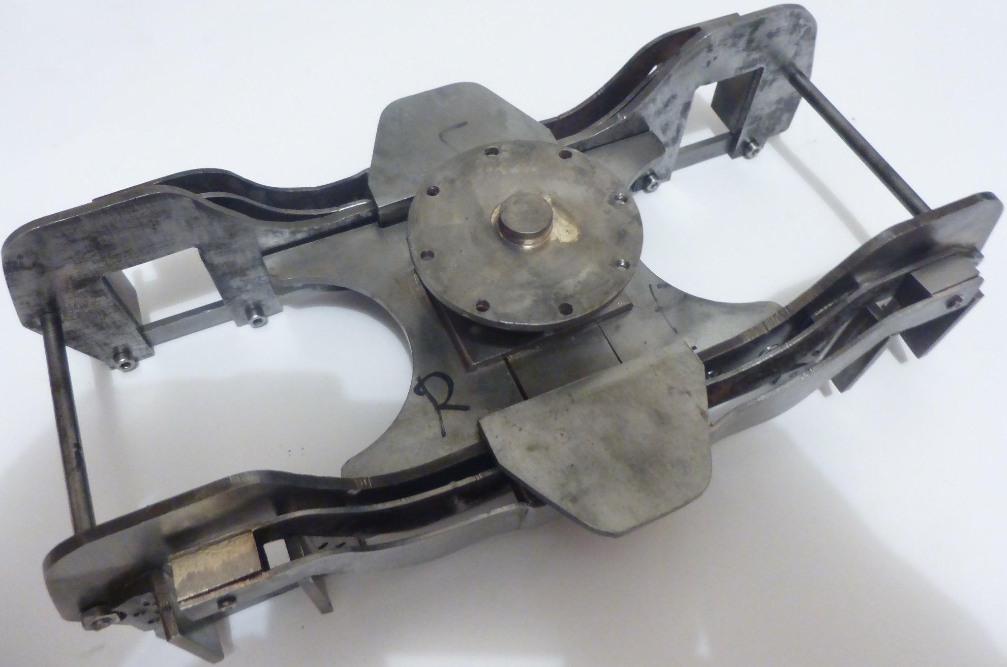 P1040170 P1040170 by Brian Leach, on Flickr  P1040168 P1040168 by Brian Leach, on Flickr |
|
|
|
Post by Jim on Nov 12, 2018 7:19:16 GMT
I have never had problems since Ben took over E J Winter but he does try to get to all the club invitation days and AALS Conferences and I believe that is where he's been lately as I got a note apologizing for the delay in getting back to me.
I'm sure you'll hear from him shortly.
Jim
|
|
Lisa
Statesman
 
Posts: 806 
|
Post by Lisa on Nov 12, 2018 8:20:02 GMT
I haven't bought anything from EJ Winter in a while, but I did swap some emails back and forth with Ben with some queries about things recently. Possibly, as Jim mentions, you might have just had bad timing in that he's off at invitation runs lately.
|
|
|
|
Post by racinjason on Nov 12, 2018 12:02:25 GMT
Brian,
I know Ben does look on here so I'm sure he will be in touch soon.
jason
|
|
|
|
Post by runner42 on Nov 12, 2018 21:56:12 GMT
I am a bit red faced, Ben in actual fact did try to phone me on the 5/11/2018 at left a message using Telstra's 101 service, however we hadn't noticed a message was left until today.
Brian
|
|
Lisa
Statesman
 
Posts: 806 
|
Post by Lisa on Nov 12, 2018 22:34:12 GMT
At least you got the message in the end; we had to drop the 101 service as it became a bottomless pit that messages would disappear into never to be seen again.
|
|
|
|
Post by David on Nov 13, 2018 22:14:42 GMT
Ben's working his @rse off to win back E&J Winter's goodwill - he's a member of my club so I know the herculean amount of work he's put in since taking it over.
I hate making phone calls (I'm an e-mail person) but a phone call will get you answers much faster than e-mails if you think something is lagging.
|
|
|
|
Post by runner42 on Nov 14, 2018 0:39:28 GMT
I phoned yesterday but got his answering machine, but I am not phased by the temporary absence it was just to understand that there was nothing more serious.
Brian
|
|
Neale
Part of the e-furniture
 5" Black 5 just started
Posts: 283 
|
Post by Neale on Dec 2, 2018 20:46:14 GMT
I'm getting near to the point that I can start assembling frame components for my Black 5 tender. Looking at the axleboxes, I can't see any provision for lubrication. No oil pad at the bottom, no way to get oil in anyway. One-piece axleboxes so not easy to machine an internal recess for an oil pad so I'm wondering about drilling an oil hole down from the top (with a small reservoir machined in?) plus horizontal hole to intersect with vertical oilway and bottom of axle hole, to be plugged after drilling. What have other people done/are going to do?
|
|
|
|
Post by runner42 on Dec 21, 2018 6:50:57 GMT
Ben phoned me yesterday to say that he had just dispatched the bogie wheels, his last activity for the year. I have made changes to DY Black 5 design and borrowed heavily from LBSC"s Black 5 Doris mainly due to ease of manufacture and that the changes wont be discernible unless you turn her over (heaven forbid). The addition of the water pump is a significant change because relying solely on injectors is not something I want to do. Also, a single mechanical lubricator is going to be at the front behind the drag beam and be operated by an eccentric on the forward axle. Some photos, as always apologies for the poor staging but I didn't want to photograph the chassis on the bench and have the picture filled with the clutter that would also be shown. 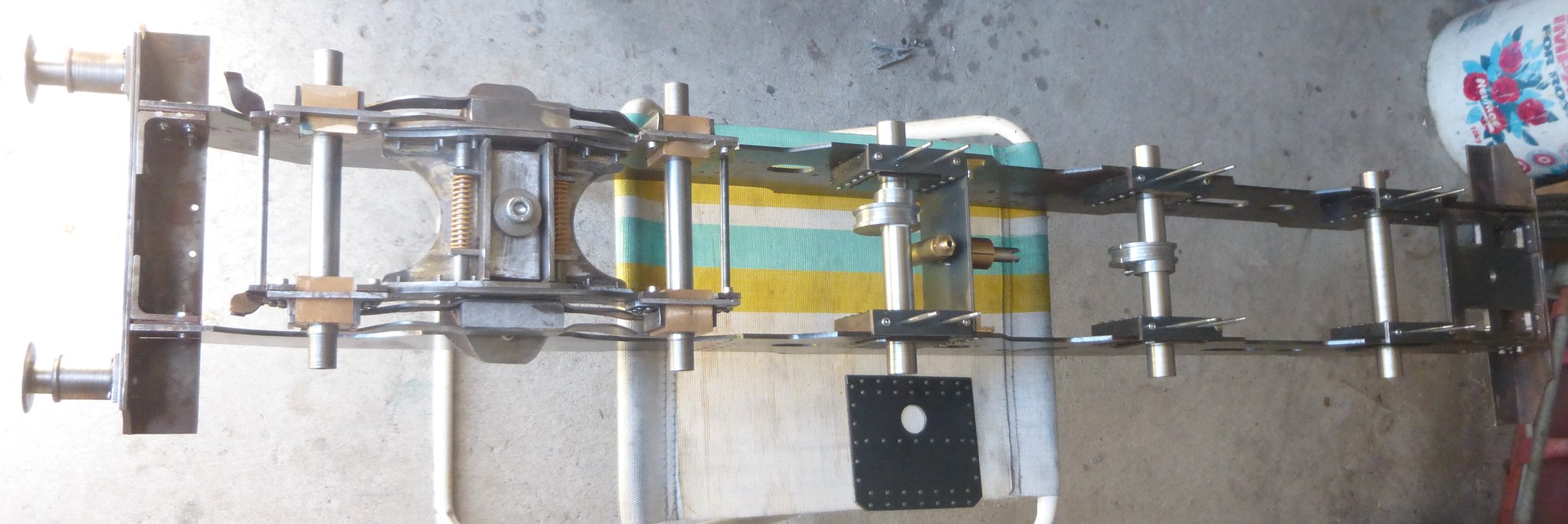 P1040187 P1040187 by Brian Leach, on Flickr 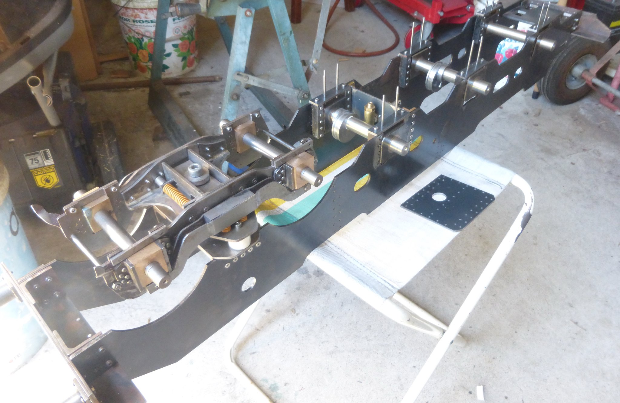 P1040188 P1040188 by Brian Leach, on Flickr 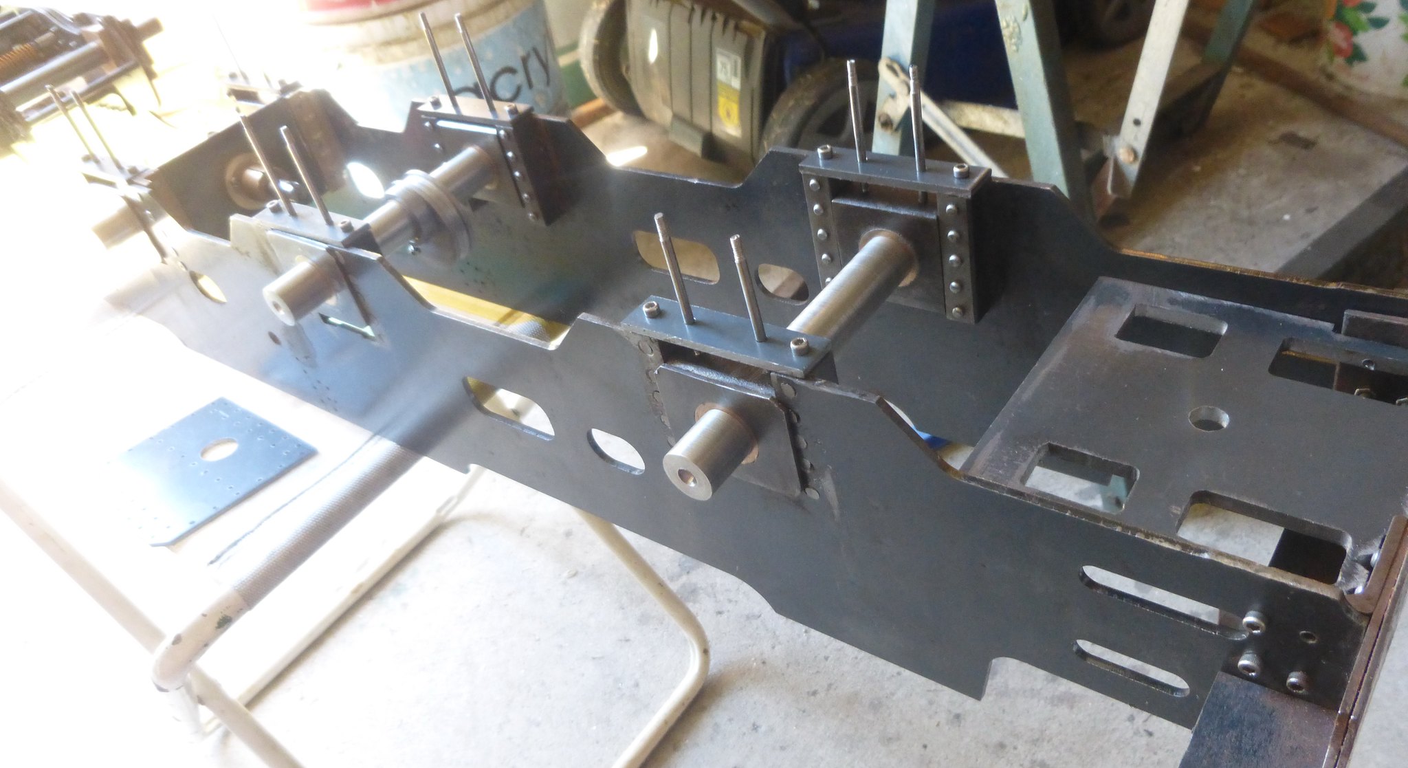 P1040189 P1040189 by Brian Leach, on Flickr 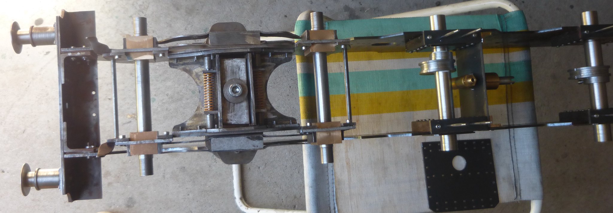 P1040190 P1040190 by Brian Leach, on Flickr 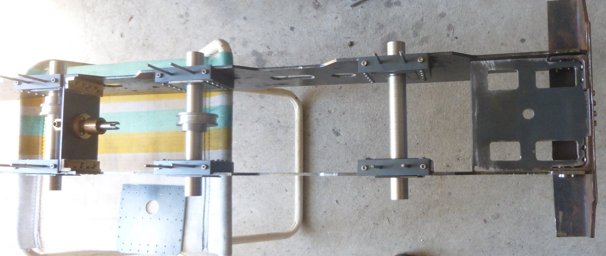 P1040191 P1040191 by Brian Leach, on Flickr The springing is another departure, preferring to use coil springs which I am procuring from China. These come ready made in a variety of sizes and found that the cost of procuring the correct SWG wire and postage costs from an Australian supplier would be comparable to obtaining ready made springs. Finally I have produced a drilling jig for the cylinders used for both drilling the frames and at a later date the cylinders. The large hole in the drilling jig is 3/4" dia and was bored using my newly acquired Boring Head for use in the Milling Machine. I couldn't bore this hole in the lathe using a 4 jaw chuck because of the size and that the hole is offset so the 4 jaw wasn't big enough. It was easily accommodated using the Boring Head. However, the first boring tool I used as soon I attempted to cut metal the cutting chip became detached because the fixative failed. Can this be re-stuck, if so using what fixative? Brian 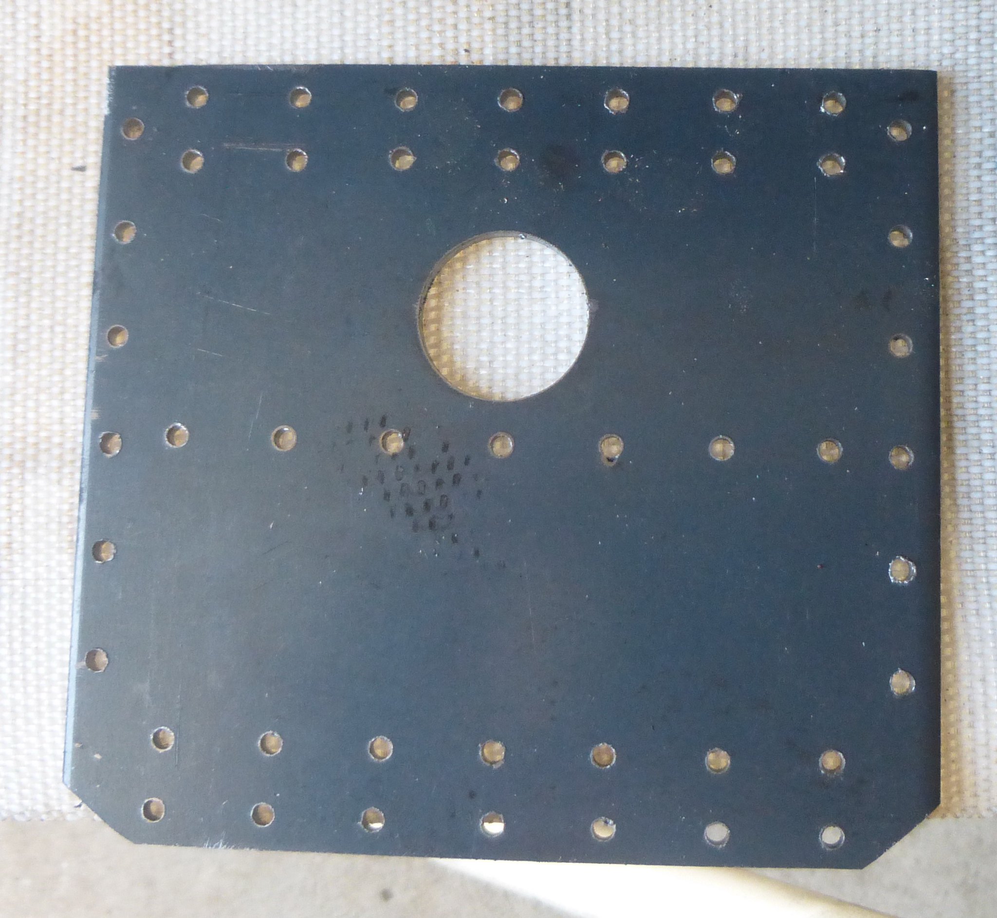 P1040192 P1040192 by Brian Leach, on Flickr |
|