|
|
Post by Roger on Jun 22, 2018 23:05:54 GMT
The way assemblies are modelled are different dependant upon what software is being used, so I can't comment on anything other than Alibre Design when it comes to specifics.
However, there are a few things to consider, some of which have been discussed elsewhere. There are others on the forum who have used 3D modelling in a disciplined commercial environment who will hopefully be able to contribute their rules to make this robust and manageable.
Mike has already touched on some of these things but here's my checklist of things I've found to be necessary to make this manageable. Alibre Design is a mid-range product that's nowhere near as sophisticated as packages such as Solidworks or Fusion360 so some of the restrictions and issues I've encountered might not present the same problems.
1) Files, folders and naming conventions...
These things can very quickly descend into chaos unless you're disciplined right from the start. Personally, I group things under bigger headings with folders such as Cab, Boiler, Smokebox, Chassis, Valve Gear etc. Inevitably there will be some overlap where you're unsure where to put something that is perhaps in the Cab but attached to the Boiler.
There are a variety of naming conventions and ideas which are worth exploring before you get too far down the line. Changing this sort of thing later isn't viable as the number of parts becomes large.
I use sub folders under the more general headings for each section, ultimately ending up with a folder for every part. That might seem excessive, but bear in mind that even a simple part might give rise to many different files as follows..
a) The 3D model
b) A 2D drawing
c) Notes on how it's made, and things you might want to record about it
d) NC files for each operation if you're going to us CNC to make it.
Some parts have 20 or more files associated with it. Either way, I've found it best to just assume that every trivial part may result in more than one file so it gets its own folder.
2) Assembling parts into an assembly...
Alibre allows parts to be loaded into a separate module where you can then define constraints to connect them. Usually it's necessary to anchor the first part so it doesn't move.
A constraint in Alibre always consists of two things that you connect in some way. That may be a diameter that's aligned with another diameter, or a face aligned to a plane.
Aligning two diameters, say a rod and a hole, is equivalent to creating a bearing which can slide along its axis. Add another constraint to tell the ends to be aligned and now it's a bearing which will only rotate.
If anything is slightly wrong, say attempting to align a pair of holes in two items where the holes are on different pitches, the software will throw an error on the offending constraint. When you get to bigger assemblies, it's possible to attempt to define a new constraint that seems completely reasonable, only to find that there are many previously defined constraints that are violated! It's not always at all clear as to why this is the case. Constraints can be fickle and hard to diagnose. Labelling them might help, but I tend to only name ones where I might return to change them, for example the angle of the pole reverser so I can check the position of the valve gear at any position.
3) Small sub-assemblies...
It seems to be better to group small sub-assemblies into bigger ones and then again into bigger ones. Alibre has a restriction in that anything that's put in a sub-assembly is fixed. For example, if I bring together the two halves of a hinge in a sub-assembly, I can move the hinge without any problems. However, if I then include that hinge sub-assembly in a bigger one, say attaching the hinge to something else, the hinge cannot then be moved without going back to the original sub-assembly and moving it there.
You have to consider this if you want to make a 3D model where the wheels turn and the valve gear animates.
4) Fixings and duplicated items...
It's probably a good idea to model the nuts and bolts and 'O' rings separately and generate parametric models for them. That enables you to model it once and then change the parameters to get the right length, diameter and flat dimensions for example. Once that's been done, you can copy it and save them into the folder pertinent to the assembly it's used on, giving it a sensible name, say "M2.5 x 10 bolt" or "O-ring 3x1section"
Adding all of the bolts looks great but introduces too many constraints which brings the computer to its knees.
A similar fate awaits a model of the boiler which has all of the tubes and stays in it. To keep it practical, I'd only model the bare minimum and leave the repeated details out unless they are useful in seeing where there are clearance issues for example.
I originally modelled both sides of the valve gear but that crippled the computer. I now only have one half modelled.
5) Maintaining a robust model...
It's very easy to end up with broken constraints and everything in disarray. Discipline is ever more important as the assemblies get bigger. I like to locate the different parts using the fixing holes that actually hold things together, ie using constraints to hold faces against faces and diameters of holes on one part to diameters on the mating piece. Alibre allows you to 'spot through' from one part to another so you can position a piece where you want it with constraints and then project hole features, for example, from one piece to another. I'm sure you can do this on other CAD packages too.
I'm at a point with my model that I really need to revisit some of the sub-assemblies and add things to those rather than how it currently is with them added to the main assembly. The boiler has too many unnecessary parts included and there are too many parts added to the main assembly. If you find yourself adding a buffer head to the main assembly, ask yourself whether that would be better added to a "buffer assembly" where two of those are attached to a "front buffer beam" assembly which is in turn added to a "frame assembly".
There are a vast number of ways to group assemblies together and I doubt if there's a 'right' way to do this. Other CAD packages work differently so you will need to look at the consequences of the different systems before going too far.
Can we please try to avoid fighting hard for our favourite CAD system, there's more than one way to skin a cat. By all means explain how certain packages work but leave it at that. Solidworks might be an awesome package for example, but if it costs £5000 (say) then it's not much use to anyone here unless you happen to get your hands on a free seat. Arguing that it's the best isn't helpful if nobody is going to be able to afford it!
|
|
|
|
Post by Mike Clarke on Jun 22, 2018 23:38:52 GMT
If you find yourself adding a buffer head to the main assembly, ask yourself whether that would be better added to a "buffer assembly" where two of those are attached to a "front buffer beam" assembly which is in turn added to a "frame assembly". Hi Roger. many thanks for taking the time to write such a detailed post - it was very useful and I'm sure others will find the same. 3D CAD is such a useful tool for this hobby and I find learning it a pleasurably part of the hobby. Your quote above describes the path I took in the end.......so that's encouraging. You are definitely correct in saying you need to be very disciplined with naming parts! So for the steps I mentioned in your build thread.......you would: 1) Create a part for top step. 2) Create a part for middle step (unless this is identical to top step). 3) Create a part for bottom step. 4) Create part for back plate. 5) Create part for left top bracket. 6) Create part for right top bracket. 7) Create part for bottom bracket. 8) Create assembly of above. 9) Add above assembly to main assembly. Just for info......I use Solidworks because I have access to it - I did download Fusion the other day (which appeals greatly as it is offered free for hobbyists), but my computer struggled to run it. I did like the look of it though and might use it as an excuse to get a new PC. Regards, Mike |
|
|
|
Post by Roger on Jun 23, 2018 9:06:08 GMT
Hi Mike,
That's pretty much the idea, but with a few changes.
I tend to model parts in ways that make them easy to modify. By that I mean use reference lines that are dimensioned from edges say, and then put holes on that line so one change in dimension will move them all. If holes need to be central to a face, I might project the faces to make a reference figure that's constrained to follow any changes I might make to the face size. If, say, the centre of the face was drawn by a reference line, that would remain in the centre of the face even if that was re-sized. Hopefully I've made that clear. The point is that if you're trying to make things to scale but you don't have the works drawings, you have to make a best guess at say the height of the step, but when it's on the model you might want to slightly adjust it to make it look right. It's then a pain if the fixing holes don't stay in the middle of the back face when you change the height.
This general method also works well when you need to make a different width step. I just change the width and then do a 'save as' on it.
In the case you've mentioned, I did that for the two middle steps because they have different fixings. I've found it better to do that than to somehow bodge it with two sets of fixings.
On this assembly, the main folded bracket is actually two parts which make up a sub-assembly. That might seem to be a bit pointless, but logically the bracket will end up as one piece so that makes sense to me.
I also attached the steps to the Cab assembly, not the main one. Again, it's easier to control if you break it down into smaller chunks.
I haven't used Solidworks but I understand it's very good. Just be aware that whatever you start the project with is going to be required to many years, and if you lose access to it then you're in trouble. Don't imagine that you will always be able to use a pirated or spare copy for example. From time to time these companies get bought and sold and change their licensing systems. Alibre was sold to Geomagic and then back to Alibre. As a result, the new versions wouldn't work with the previous owner's licensing system and I was forces to take up maintenance again to be able to use it. I don't know what the future holds for Fusion360, but it looks like it wouldn't cost too much to pay a monthly subscription to keep it. if that's how it turns out in the end. It's hard to see it remaining free forever for hobbyists and small businesses but I may be wrong.
I think you need a pretty good PC to run any of these programs with large assemblies.
|
|
|
|
Post by Mike Clarke on Jun 23, 2018 10:54:27 GMT
Many thanks for explanation Roger. It will definitely be of help. Moving holes has definitely been a pain in the past!!
I'm sure there is a chance the free Fusion360 will be another Photobucket.
Regards,
Mike
|
|
|
|
Post by Roger on Jun 24, 2018 19:51:31 GMT
I've started to put the bunker back together in a more robust way. The model below adds about as many new parts as I'd add now. As soon as you add more parts, it can end up in a mess that's hard to put back together if any of the contstraints are disrupted. So this assembly is left like this, and the next assembly adds this as a single component. 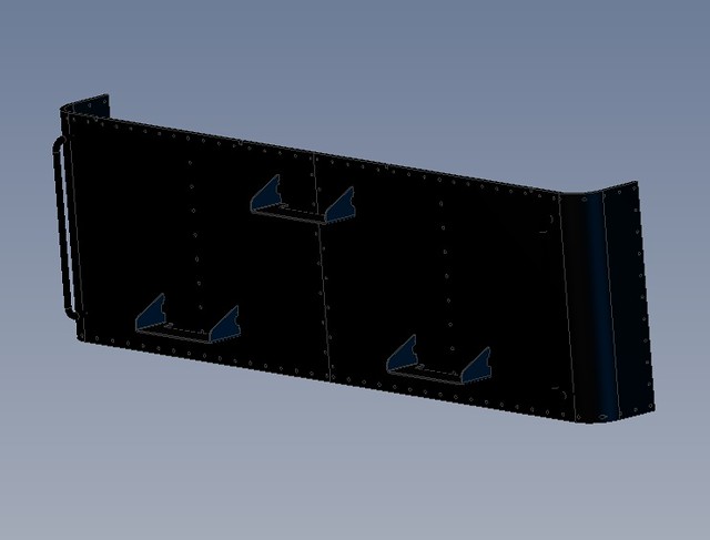 Lower curved back assembly Lower curved back assembly by Roger Froud, on Flickr Here's another example of an assembly that won't get any bigger. If something needed to be added to the step for example, it would be added here and NOT to a bigger assembly. The idea is to leave as few things as possible that need to be added to the top level assembly 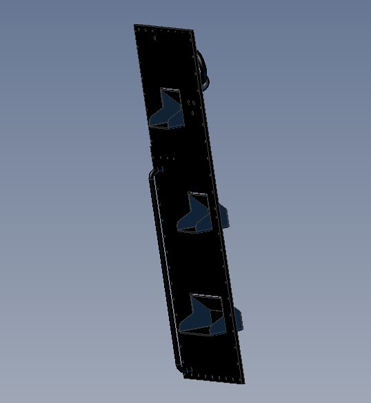 LH Bunker side assembly LH Bunker side assembly by Roger Froud, on Flickr So moving on, this encapsulates multiple sub assemblies, each adding say four new items the sub-assembly that we're adding to. 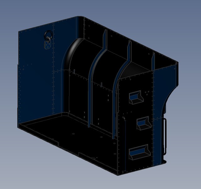 Bunker base with back and sides Bunker base with back and sides by Roger Froud, on Flickr This is very different to the last way I did things. I had the whole bunker as a single assembly, adding things piecemeal to the base plate and building up without any sub-assemblies. 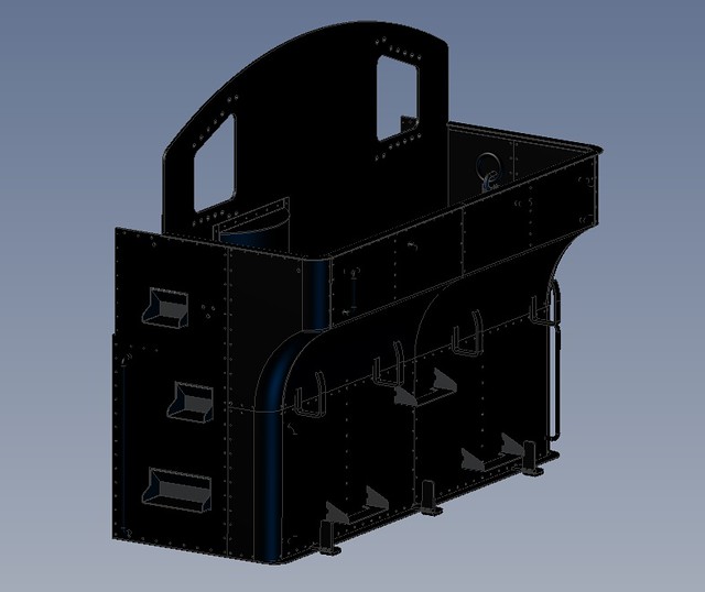 Bunker base with back sides front and cab rear Bunker base with back sides front and cab rear by Roger Froud, on Flickr In some cases the sub-assemblies are really simple. For example, the RH bunker side is just the side plate with the lifting eye assembly on it. The lifting eye is an assembly of the base and the ring. In the above image, the Base originally was made into a sub-assembly which had just the lamp brackets attached to it. Maybe this is not the way to go about things, I'd be interested to know what professional and much better disciplined designers do. I know there are different types of CAD system that work in a different way. Given the constraints of my particular system though, this seems to be a much better way of stopping the whole model turning into a monster with hundreds of constraints and no clear order of being created. |
|
kipford
Statesman
 Building a Don Young 5" Gauge Aspinall Class 27
Posts: 566 
|
Post by kipford on Jun 24, 2018 20:55:35 GMT
Roger
Apart from the obvious top level assembly model. Assemblies and sub-assemblies models are normally configured around how the part is to be manufactured. For example in model engineering terms an obvious one would be the boiler. However within this could be sub assemblies such as the firebox front plate and the tubes. Note though that these assemblies will evolve all the way through the design process. The way to avoid constraints and minimise problems of parts 'moving' is draw where possible all the parts to the same datum axis system. The exception to this is standard parts such as 'o' rings and fasteners. This is pretty much standard aerospace practise and I use it for all my own projects.
Dave
|
|
|
|
Post by Roger on Jun 24, 2018 21:09:49 GMT
Roger Apart from the obvious top level assembly model. Assemblies and sub-assemblies models are normally configured around how the part is to be manufactured. For example in model engineering terms an obvious one would be the boiler. However within this could be sub assemblies such as the firebox front plate and the tubes. Note though that these assemblies will evolve all the way through the design process. The way to avoid constraints and minimise problems of parts 'moving' is draw where possible all the parts to the same datum axis system. The exception to this is standard parts such as 'o' rings and fasteners. This is pretty much standard aerospace practise and I use it for all my own projects. Dave Hi Dave, Thanks for that, I suppose that's pretty much the way my thinking has evolved. When you start with no idea what you're doing, things quickly get out of hand. I'm not quite sure I know what you mean about "the same datum axis system". I do sometimes use say the Z axis as the reference and make each item aligned to that is they're all concentrically aligned rather than constrain them to each other. Is that what you mean? In Alibre, the axis system from a sub-assembly seems to be lost when you add it to a larger one. There doesn't seem to be a way to carry an axis that was used as a reference across. When making assemblies, I first constrain the first item to the planes else adding other parts can cause the first item to move when usually that's the one I want to base that assembly on. The biggest single pain in my opinion is that there's no alternative but to add all of the Wheel sets and individual valve parts to one final assembly so that it can be animated. I would have thought that you could have moving parts carried across but that doesn't seem to be the case unless I'm missing something. That does necessarily mean that the final top level assembly has an awful lot of constraints because there are so many pieces in the valve gear. As it is, I'll only model one half else it cripples the computer. This time I'm going to be very conscious of where I add any new parts as I build it all up. It would be interesting to show Alibre to someone who's used to working in an commercial environment to see what they think of the tools. My guess is that they wouldn't be that impressed! You have to learn its ways and how to stay out of trouble. Go about things the wrong way and it bites back. |
|
kipford
Statesman
Building a Don Young 5" Gauge Aspinall Class 27
Posts: 566
|
Post by kipford on Jun 25, 2018 20:52:54 GMT
Roger
The datum axis or global axis is the axis system at X, Y0, Z0. I use CATIA V5 which is the Aerospace industry standard and totally unaffordable unless you a know man who (I will stop here). In Catia if the part is created as the first part in an assembly the axis system in that original part becomes the 'global axis' for the assembly. If you create a new part inside the assembly, then you are asked if you want to use the global axis or define a new one. However if the part is created outside of the assembly, eg using a standard part, then when that part is added to the assembly, it will appear at X0, Y0 Z0 of the global axis and constraints will probably be required to position it. I would expect Ailbre to operate in a very similar manner. The beauty of using a global axis system for as many parts as possible is that if it all goes T"%$ up then you can reassemble the model a lot quicker, in the knowledge they will be in the correct position. Reference carrying parts across assemblies for doing the kinematics, Catia is the same as Ailbre, the parts you want to move relative to each other have to be in the same assembly, I do not know of any system which does it any other way. By the way,I do not see anything fundamentally wrong in your modelling approach, unless you are bound by a company standard, work to what suits you.
Dave
|
|
|
|
Post by Roger on Jun 26, 2018 6:56:56 GMT
Hi Dave,
Thanks for making that clear, I see what you mean now. I've done a little research and referencing to global axes doesn't seem to be supported. I can't find it in any search and the tutorials don't mention it. I do notice that when I add a new part to an assembly, the origin of that part or assembly is the point by which I have hold of it though. The doesn't seem to be available as anything you can reference to though.
So in a nutshell, you are stuck with having to reference any new items to the local axes, planes or features. That's a bit of a pain when you have to set a part equidistant astride a plane for example because there's no way to reference the middle of a line or a face. I usually have to set an outer face to the central plane with a precise offset which isn't ideal.
Having said all that, my new heavily nested method of assembly does mean that you can't end up with the whole thing going awry because those local references to each nested local set of axes can't be destroyed unless you go into that nest level and mess it up there. Heavily nested assemblies certainly seems to be a much more robust way to go about things even if it's more challenging deciding where parts and sub-assemblies should live in the folder structure.
I've broken down the locomotive into big chunks and kept the top level away from other stuff so the structure starts like this...
Top level folder - 3D Model (keeps it clear of pictures, turning frame, rolling road and other stuff)
2nd level folders - Accessories and other parts, Boiler and fittings, Cab and bunker, Chassis, Side tanks, Smokebox
etc etc - The Accessories and other parts hold things that don't logically go anywhere else, for example the common lifting link that goes both on the top of the side tanks and also inside the bunker. I've also included the injectors in there but you could argue that they could go in the Boiler and fittings one.
The thing I've tried to do is to limit the number of folders at this level to mostly big chunks of locomotive so they can be found more easily. I had way too many folders at the top level before and it became confusing. You could argue to do it in other ways but I don't think there's an ideal and obvious one. There are shortcomings with whichever structure you choose.
I'm glad it's not just me that can end up with it all going horribly wrong, it sounds like it happens to professional designers with professional software!
Anyway, I very much appreciate your input, I had no idea how these things were done commercially.
|
|
|
|
Post by Cro on Jun 26, 2018 7:47:21 GMT
Roger,
I think a good way to look at it is a top down approach where by your very final assembly of the whole loco only ever has sub assemblies built into it E.G. Boiler (with or without fittings), Tanks, Cab, Chassis and so on. That way you can work out what sub assemblies you need and go from there (which sounds like what you are doing anyway).
I think Solidworks is slightly different to the above mentioned. The first part into the assembly is fixed X Y0, Z0 all other parts dragged in are in free space and can be pretty much anywhere which can be quite frustrating at times especially if you drag and drop copy of a part where you think is next to the old one is totally off in at least one axis. All parts can then be mated in a variety of ways from simple face mates, concentric, tangent, distance, angle and so on but it has some clever mates for slots, width where by it can be central, free between faces or % off set about centre and so on and then they have mechanical mates for moving parts/gears and mechanisms which I rarely use but are good when you want to animate things like the BR Gearbox I did. It's pretty flexible and clearly shows in the part tree which items are unconstrained.
Are you not able to leave parts unconstrained in the sub assembly and then when in the top level assembly set that sub assembly as "flexible" as it is in SW which allows any un-constrained parts to move or be constrained in the top level. For example your hinged doors, build the bunker with the hinges in place but the door not set in any particular position, in the next level up this would be set as flexible allowing you to move the door. Same for Valve gear if you were to build the cylinder with pistons and valves as one sub assy. or the axle pump as its own sub assy.
I found using Solidedge is much harder to do all of these things, its very counter intuitive especially for modifying tasks and commands - I don't like it!
I am soon going to start modelling the 4MT, I'll describe in the build thread how I go about assembling some of the sub-assemblies and build it up as I go as the only updates for now will be around the CAD model rather than in the workshop.
Adam
|
|
|
|
Post by Roger on Jun 26, 2018 9:16:05 GMT
Hi Adam,
I've had another play with a simple sub-assembly with two parts that are hinged together with constraints. When I insert those into another assembly, they become fixed.
If I then choose 'make flexible' for those. Initially I couldn't make this work, the parts just detached from each other, so I don't know what I did wrong. I've now got it so that I've got two parts hinged together as the first sub-assembly. Those are then put into a second sub-assembly and hinged with another part. Finally I'd pulled that nested assembly into a final one.
I can now make this do what I need. You have to go into each nest level and select 'make flexible' at each stage which makes sense. I've had a habit of using Anchor to keep parts from moving about when I've been making a sub-assembly. That's not a good idea as it turns out because if you do that for a part that needs to move, it sometimes remembers that and you can't make it flexible. Why this is allowed sometimes and not others is a mystery. It's probably best not to use it at all.
I've seen things that could move correctly in the past, but never figured out what the restrictions are. It seemed like it just worked sometimes and not at others and for no good reason. Now I know it can work and what the rules seem to be, I ought to be able to put together the valve gear as follows...
1) Add the bushes to each of the links as individual sub-assemblies. (we don't make these flexible later because we want them to stay put)
2) Make up the expansion link fixed parts excluding the sliding piece.
3) Add the sliding piece and expansion link together in one sub-assembly so they can be 'made flexible' allowing the slider to move
4) Add each link sub-assembly to an overall layout so that the pivot points are defined, making the sub-assemblies flexible.
5) Finally add the whole of the valve gear to the chassis in one piece, attaching the various parts of the valve gear to the wheels and crosshead, making them flexible.
So it looks like this is the way forward and makes life a lot easier. I should be able to make the Cylinders and piston assemblies movable as insertable sub-assemblies which will make it a lot less clumsy.
When I look at the Design Explorer tree, it hides the embedded constraints in those sub-assemblies which will make it a lot cleaner. Adding lots of parts to a final assembly results in a crazy number of constraints and items in the Design Explorer. I can now see how to cull those and make the whole think much more manageable.
Hopefully this will also make the model easier for the computer to deal with and maybe it will speed up the loading.
Maybe there's a tutorial that explains this stuff, but I'm yet to find anything other than ones on how to get started.
Anyway, it's all good and I've learned a lot from the replies.
|
|
|
|
Post by Cro on Jun 26, 2018 9:31:28 GMT
Roger,
Glad it was useful, Doing these assemblies all the time at work having SW makes life so much easier.
When I was at my last place working on the revolving glass screen this flexible function was perfect as I could assemble the runners, guide rail and glass in one sub assembly and then when in the next level up with the frame and heater hot zone you could see the glass rotating and how it integrated into the system.
You should be able to do some nice valve gear simulations & videos now!
Adam
|
|
|
|
Post by Roger on Jun 26, 2018 10:06:49 GMT
Roger, Glad it was useful, Doing these assemblies all the time at work having SW makes life so much easier. When I was at my last place working on the revolving glass screen this flexible function was perfect as I could assemble the runners, guide rail and glass in one sub assembly and then when in the next level up with the frame and heater hot zone you could see the glass rotating and how it integrated into the system. You should be able to do some nice valve gear simulations & videos now! Adam Let's hope so. I've done it in the past but it was fragile and clumsy. Now I've got a better handle on how the system handles it, life should be a lot easier. |
|
kipford
Statesman
Building a Don Young 5" Gauge Aspinall Class 27
Posts: 566
|
Post by kipford on Jun 26, 2018 12:41:21 GMT
Adam
Despite logging about 10000 hrs on CATIA over the years you still learn something new every day! All my previous work was involved static structures, with only the occasional door assemblies and like, where a simple 2D sketch could be used to determine movement and similar. In the main we tended to avoid constraints using the snap to etc functions you describe above and then fixing the position. Checking the interweb Catia V5 also has a flexible constraint system and I will be investigating it. However for fixed components using a single global axis system still prevents a lot of problems. PS CATIA V5 and SW share the same architech.
Dave
|
|
|
|
Post by Roger on Jun 26, 2018 20:41:15 GMT
The new found understanding of making whole assemblies flexible has absolutely transformed the way moving assemblies can be constructed. The gear frame is nested as follows... 1) The static elements of the frame are one assembly 2) The static frame is added to a new assembly as a single part and the various bushes are then added. These could have all been added to the first one but it would have ended up with a lot of constraints and I'm trying to minimise the complication at each level. 3) The LH expansion link complete but without the die block is one assembly as is the RH one 4) The pair of die blocks and their joining pin is one assembly, with the die blocks set at the correct distance apart on the pin and at the same orientation. 5) Each expansion link is then inserted into a new assembly and the die block assembly is added to that and constrained to the curved inner face of the expansion link. The key thing is that there are only two pieces being connected here, the whole of the expansion link and the whole for the die block assembly. That's so that at the next level up, I can tell it that this new, two piece assembly is flexible and the only things that can move are those two parts relative to each other. 6) A new assembly inserts the gear frame complete with bushes and the two expansion links, so this is effectively a three piece assembly. The key thing is to go to both of the expansion link assemblies in the Design Explorer and tell them to be flexible. Remember, it's only the die block assembly and the expansion link assemblies that move relative to each other, not the parts that make those up! 7) The weighshaft assembly is the shaft and the two arms, that's just a fixed assembly. 8) Finally, a new assembly has the 'gear frame with the expansion links' assembly added as well as the weighshaft assembly. I could have added the weighshaft at the previous level, but I kept it separate in case I change my mind as to where it gets added. Again, the whole of the previous 'gear frame with expansion links' assembly has to be set to flexible else it's all locked again. Once that's done, you can still slide the die blocks up and down the expansion links and pivot those too. This works really well and allows big functional blocks to be build and then added in one piece for connecting up later in the final assembly. It massively simplifies the model at the final stage and so far I can't see anything that's going to cause a re-think. So far, so good. 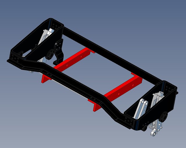 Gear frame assembly with expansion links and weighshaft Gear frame assembly with expansion links and weighshaft by Roger Froud, on Flickr |
|
|
|
Post by Roger on Jun 27, 2018 20:33:16 GMT
Here's the brake hanger and pull rod assembly which fully articulates. The key thing to take away from this is that this assembly is robust and can't be damaged when it's inserted into a more complete model. This is still one part as far as inserting it is concerned. On my original locomotive model, these parts were added to the main assembly, and as a result there were dozens of constraints at that top level to connect them. Small changes to the top assembly can accidentally cause conflict with these and then you're in trouble because it's far from easy to find where it's gone wrong in the sea of constraints. I have attempted this sort of thing before and ended up with it locked solid though. Today, I built this assembly using the original trivial assemblies where the rod ends were attached to the pull rods. I couldn't get this to articulate and then spotted that I'd used anchors on all those trivial assemblies. I went back and removed those anchors but found that the front rod just wouldn't articulate, even though the others would. Eventually, I deleted that front rod assembly and made it again. That then worked without any further problems. This makes me think that there's a bug in there that on occasion can somehow prevents a previously anchored part from being un-anchored. This sort of issue is the reason I gave up on it years ago, it just seemed flaky and prone to just lock up, leaving me wondering what had gone wrong. Encapsulating the articulation in small bite sized chunks protects them from these problems. Edit:- The below arrangement seemed like a good idea, but it doesn't work. I've found that when you add a complex assembly like this, make it flexible and then add new constraints, it complains that it's over constrained, even though to my eyes it isn't. Maybe I'm missing something? 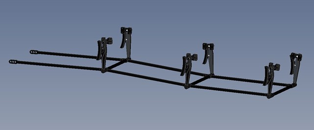 Brake hangers and pull rods Brake hangers and pull rods by Roger Froud, on Flickr Another job done. This time I should be able to add it to the cylinder and still be able to move the piston. I will have to add at least another nesting level for the cylinder though, one where I can add things like the drain cocks, relief valves and cleading. 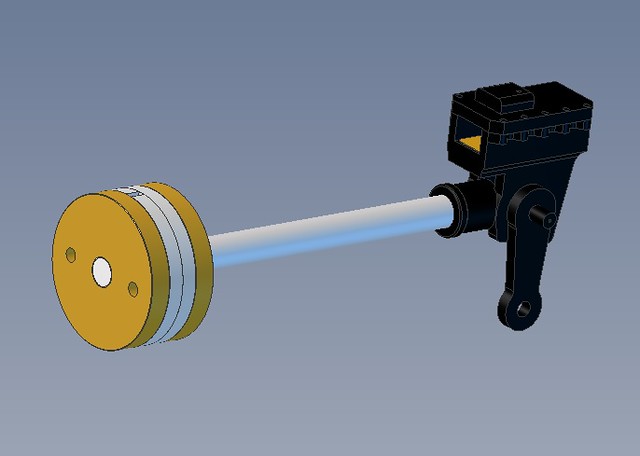 Piston with rod and crosshead Piston with rod and crosshead by Roger Froud, on Flickr |
|
|
|
Post by Roger on Jul 2, 2018 22:15:11 GMT
Once again I've nested sub-assemblies to minimise the number of constraints at each stage and protect them from corruption. Adam's revelation of making assemblies flexible led to a novel idea. The boiler tubes were brought into an assembly on their own, then constrained all of their ends to be held to the XY plane you can see at the right of the picture. 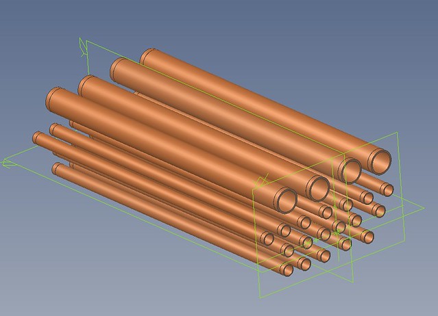 Tube bundle with ends aligned Tube bundle with ends aligned by Roger Froud, on Flickr That jumble of tubes was them included as a sub-assembly which was then made flexible. The result is that the 22 constraints keeping the ends level were then hidden from view, but I was able to align the tubes with the holes in the firebox. That made it much less cluttered and more robust. Only one tube had to be mated at the end, and any changes to that were then easy to adjust. The smokebox tubeplate is a sub-assembly which includes the regulator bush and the attachment points for the four longitudinal stays. The firebox was also a separate sub-assembly which also included a sub-assembly for the fusible plug. You could probably argue that I've nested it unnecessarily deeply, but it keeps each level down to no more than 30 constraints. The number of constraints can spiral out of control very quickly when you add 22 boiler tubes.  Inner firebox assembly with tubes Inner firebox assembly with tubes by Roger Froud, on Flickr |
|