|
|
Post by keith1500 on Jan 18, 2020 11:35:47 GMT
It is a very difficult subject and with so many interpretations... People over pickling in citric acid injectors to clean them and destroying the innards... Roger was shown a startling extreme example of this sent to me that was a 'bin job'. On the other hand, I did stress to Roger that I had an excellent Linden injector that was some 70 years old and still works perfectly albeit with a new steam cone of Bob Bramson's design. The problem with over pickling injector innards to clean them, and applying a pair of pliers to remove the delivery cone and steam cone is just way off my radar for all this! I think the first stage in all this is to make accurate reamers that cut keenly and are dead sharp and with a dead smooth finish... I've seen Roger's Jones Shipman grinding machine, and if anyone can make dead sharp accurate reamers of the required tapers accurately then it would be Roger! Cheers, Julain I wonder if that was my injector? Its easy to fall in the trap of not treating these delicate little pieces of precision badly. It was never drummed into me how best to treat injectors. I had met someone who advocated the use of viakal the kitchen descaling fluid. They advised carrying some in a syringe along with a short length of clear pipe. If on the run your injector packs up give it a shot of this I was told. Leave five minutes and flush out. Well it saved the day on a few occasions but then I started to use it as my preparation. The thing is you don’t realise how corrosive some of these products are. Be warned!  Steam come 22oz JC Steam come 22oz JC by GL5Keith1500, on Flickr |
|
pault
Elder Statesman

Posts: 1,496
|
Post by pault on Jan 18, 2020 18:14:47 GMT
When one hears or reads that such and such a design that some one has made does not work well, I some times wonder if it is the details of the design or the fault lies in the execution of making the item ?
I suspect injectors often fall into this question.
Any how, I like the idea of making my own injectors one day soon and this thread will be most interesting for me.
I am also interested in how small a working injector can be made ?? I’m quite sure that some injectors that are made to published designs fail to work due to manufacturing issues rather than the design. I am equally sure that a significant percentage of injectors that ‘don’t work’ fail due to the plumbing around them. When presented with a new loco with injectors that don’t work the first thing I would try is to put an injector on that is known to work. Very often the injector that is known to work will not work on the new loco. Generally it boils down to something like water filter restricting the flow, steam or water passage through a valve being too restrictive, air leaks and other similar things. Don’t be quick to condemn the injector. As for pickling injectors, in my view many people over do this. I have run injectors for many years without pickling without any problems. Nine times out of ten injectors fail because of the plumbing around them, blocked filters restricting the flow or foreign objects disrupting the flow through the cones. |
|
jma1009
Elder Statesman
Posts: 5,900
|
Post by jma1009 on Jan 18, 2020 21:26:20 GMT
Hi Keith,
Yes, it was your examples that Roger examined on Wednesday, though this was only because they were still to hand - I could have shown Roger other examples, but time was short, and I suppose it only requires one example to prove a point! (Incidentally, I have never had your address to return the 2 injectors to you).
To link up with 'Oily Rag's' point quoted by pault, Roger was also shown the 2 examples from Chris Vine sent to me, and Roger was provided with a basic explanation that these have a combining cone taper greater than 13 degrees, instead of the accepted 9 degrees taper.
I've come across quite a few of these commercial examples with the wrong taper for the combining cone. Brian Leech ('runner42') sent me an example, and as he had gone to some considerable trouble to send it from Australia, I spent a great deal of time on it; making a new steam cone and delivery cone to match the combining cone, which were originally mismatched for throat sizes.
I suppose I wanted to test that a 9 degree taper for the combining cone could be greater - after all, someone was peddling these injectors through the trade, and it would seem odd that anyone would sell something that wouldn't work!
But it was all to no avail; the performance (with new steam cone and delivery cone) was very poor (unacceptable IMHO) with the 13 degree combining cone taper.
Commercial injector makers such as Arthur Grimmett and Gordon Chiverton, who made lots of other boiler fittings as well, did not have the luxury of a lathe exclusively used for injectors and permanently set up for same, and there are differences in the batches of injectors. Malcolm Brown ('mbrown' on here) sent me 2 Gordon Chiverton injectors that were clearly made up of odds and ends, probably shortly before Gordon died. I haven't looked up this evening the report I provided to Malcolm, but one was full of swarf, and one had a blob of silver solder on the check valve seat preventing the check valve ball seating, and one had a delivery cone that was the wrong length. These were bought by Malcolm in good faith from one of our 'reputable' suppliers.
Ron Hancock sent me lots of commercial injectors he had bought which had a 13 degree combining cone taper that he couldn't get to work - I sent him one of my own that I knew worked perfectly - as pault mentions, to test the auxiliaries on Ron's loco, and Ron wrote me a very nice letter subsequently saying in effect how nice it was to have an injector that worked as it should. I tested all of Ron's commercial examples - none of them worked, that re-enforced my conclusions from testing and altering Brian Leech's example from the same maker that a 13 degree taper for the combining cone just won't work.
So, yes, there are commercial examples about that don't work.
Conversely, in the USA, they appear to have very good suppliers of miniature injectors, though at a considerable price. They are prepared to pay the equivalent of £200 - £300 for a decent working miniature injector. (I follow Anthony Duarte's threads on the Chaski USA forum).
Roger's recent posts on this thread have been excellent BTW.
Cheers,
Julian
|
|
oldnorton
Statesman
 5" gauge LMS enthusiast
Posts: 692
|
Post by oldnorton on Jan 19, 2020 11:12:15 GMT
Yes, very good to read your thoughts about injector design Roger.
Could you give a drawing of what you mean by 'end regulation adjustment by grub screw'; my brain cannot visualise it. Are you thinking of 'pushing' the steam jet closer or do you just mean a permanent (screw set) valve in the water feed line? If the latter will this not affect initial pick up?
Norm
|
|
|
|
Post by Roger on Jan 19, 2020 12:48:22 GMT
Yes, very good to read your thoughts about injector design Roger. Could you give a drawing of what you mean by 'end regulation adjustment by grub screw'; my brain cannot visualise it. Are you thinking of 'pushing' the steam jet closer or do you just mean a permanent (screw set) valve in the water feed line? If the latter will this not affect initial pick up? Norm It's the latter I had in mind. The steam cone position would be fixed. Whether a restrictor would prevent it picking up or not is hard to know. I think it just needs to be tried to find out. If you can do it that way then it would make life simpler. |
|
robmort
Hi-poster
 3.5" Duchess, finishing 2.5" gauge A3 and building 3.5" King
Posts: 172
|
Post by robmort on Jan 19, 2020 18:35:26 GMT
So in point 1) The ideal is that the design 'cone' shape has all three throats lying on it. I don't see the point in deviating from that. Agreed and I think you'll find that's standard pactice in established designs certainly for the Mixing and Condensing, and also practically for the Delivery cones. The way these cones are usually made in my experience (and in the books) is to use the reamer first then the outside is turned down very carefully to avoid distortion. They usually last years in my club. The reason they are made thin is so that the steam and water flows converge with minimum impedance. This cannot happen with end-regulation which introduces the water virtually at 90deg to the steam so it's not clear how effective this is. I agree and that's exactly what is needed, as there is already plenty of theory. As you say, experiments have been done by many of us in terms of restricting the water supply and it's easy to do qualitatively at least, by an adjustable valve to control the flow and optimise the delivery to the boiler. I've found that it's not easy to adjust operation this way even with a larger annular gap. Another simple way to show this effect is to use a flexible water supply hose and squeeze it variably between fingers to see what happens, but again results are not near linear or easily controllable. I'd be very interested in your results. |
|
|
|
Post by Roger on Jan 19, 2020 20:49:46 GMT
BEWARE, the following is highly speculative and probably won't work! Anyway, here's a first draft of all of my thoughts lashed together in a form that could be made to fit a standard GWR injector body. Making the main cones in one piece means they don't have to be a super precision fit in the body. Obviously it still has to line up with the Steam cone, so it can't be that far out though. The gaps between the cones have been replaced by three rows of 0.3mm dimeter holes 0.4mm apart axially and repeated 16 times around the body. That leaves a fair bit of meat around the outside while breaking into each other on the inside. The regulation on this ones is done by small holes drilled through the supporting ring on the outside of the Steam cone. The alternative would be a grub screw with a hole in it in the water inlet pipe. In that variant, there would be large holes in the support ring instead. I think this idea is where it's more likely to fail than anything else. That's because it might not start with the restriction away from the end of the Steam cone. However, there's only one way to find out! NB:- The flow in this diagram is from Right to Left Injector first draft Injector first draft by The train Man, on Flickr Here you can get a better idea of what would normally be the three different cones on the left, ie separated by the perforations. I appreciate that a large number of holes will have more restriction than a gap, both because there's less cross sectional area as well as more surface area to cause friction. Who knows, a further row of holes might be needed.  Sectioned injector first draft Sectioned injector first draft by The train Man, on Flickr There will be a non-return valve on the overflow that services both sets of holes. That will be a separate item bolted on the bottom of the middle flange, like the real thing. I'm of the opinion that you don't need separate valves for these, but I may well be wrong. Ultimately, this is not a sensible thing to do in one hit, a better approach would be to try each element separately and get a handle on the effectiveness of each new idea. However, I'm not sensible, so I'll probably detail the whole thing and just give it a try and then go from there. I can hear everyone thinking that the holes are a nightmare to drill, and it's easier to make them as individual cones. As always, it's a trade off. If you ignore the holes, it's much easier to do it this way, so if you can drill the holes easily, you're onto a winner.... if it works! This is the sort of project that I need to finally get me to make the 4th axis so I can just program in the holes and walk away. See what I mean...
|
|
|
|
Post by keith1500 on Jan 19, 2020 21:30:52 GMT
Well it’s pretty radical, I am like it a lot.
It over comes lining everything up and it would be easy enough to swap out for another unit.
You do realise you’ll probably need a small test plant unless you borrow one.
The holes still scare me but you are so much braver than most of us. A 4th axis would help keep you sane me thinks!
Keith
|
|
|
|
Post by Roger on Jan 19, 2020 22:15:21 GMT
Well it’s pretty radical, I am like it a lot. It over comes lining everything up and it would be easy enough to swap out for another unit. You do realise you’ll probably need a small test plant unless you borrow one. The holes still scare me but you are so much braver than most of us. A 4th axis would help keep you sane me thinks! Keith Hi Keith, I've got some Steel tube to make a test boiler, I just need to source a suitable electric cartridge heater. The holes are not especially difficult if you take your time. Just don't expect to be able to drill them with a hand lever feed. |
|
jma1009
Elder Statesman
Posts: 5,900
|
Post by jma1009 on Jan 19, 2020 22:48:19 GMT
Hi Roger!
Go for it! It is only by this departure from the 'norm' that you will find out, and you have the kit and precision engineering experience to test this theory of yours.
It is rather a shame that 'Kipford' went on holiday earlier this year when the convergent taper to the inlet of the steam cone was being discussed... perhaps Dave can be persuaded to comment further on this.
You would be more than capable of making the cones with precision fits, so myself I don't see any need for the 'O' rings, except the crushing effect on your holes as they are pressed in. A standard 24-26 oz per minute injector usually uses a 7/32" bore through the body; you can go down to 3/16" for a 16 oz per minute injector.
I cannot see how the water inlet gets to the gap between start of the combining cone and end of the steam cone on your above 2 pics.
I am somewhat reminded of Bulleid, and not introducing too many new features untested, and a step by step approach might be preferable, otherwise you will not be able to fathom where problems are occurring.
Hi Rob,
I can say that the 'end regulation' steam cone I fitted to Bob Bramson's design works perfectly, and I discussed with Roger on Wednesday how this ought to be capable of a formulae - probably via CAD - to give the required annular gap. The method I use for the annular gap is not suitable for the Bramson steam cone - but it is not impossible to derive a way of doing this with the Bramson type steam cone, and certainly within Roger's capabilities, and would avoid a stainless grub screw restricting the water flow - which I have problems getting my head round so far as getting the injector to pick up is concerned.
Cheers,
Julian
|
|
|
|
Post by Roger on Jan 19, 2020 23:32:14 GMT
Hi Roger! Go for it! It is only by this departure from the 'norm' that you will find out, and you have the kit and precision engineering experience to test this theory of yours. It is rather a shame that 'Kipford' went on holiday earlier this year when the convergent taper to the inlet of the steam cone was being discussed... perhaps Dave can be persuaded to comment further on this. You would be more than capable of making the cones with precision fits, so myself I don't see any need for the 'O' rings, except the crushing effect on your holes as they are pressed in. A standard 24-26 oz per minute injector usually uses a 7/32" bore through the body; you can go down to 3/16" for a 16 oz per minute injector. I cannot see how the water inlet gets to the gap between start of the combining cone and end of the steam cone on your above 2 pics. I am somewhat reminded of Bulleid, and not introducing too many new features untested, and a step by step approach might be preferable, otherwise you will not be able to fathom where problems are occurring. Hi Rob, I can say that the 'end regulation' steam cone I fitted to Bob Bramson's design works perfectly, and I discussed with Roger on Wednesday how this ought to be capable of a formulae - probably via CAD - to give the required annular gap. The method I use for the annular gap is not suitable for the Bramson steam cone - but it is not impossible to derive a way of doing this with the Bramson type steam cone, and certainly within Roger's capabilities, and would avoid a stainless grub screw restricting the water flow - which I have problems getting my head round so far as getting the injector to pick up is concerned. Cheers, Julian Hi Julian, If you look carefully at the disc on the Steam cone, you'll see that I've added four small holes in that to allow the water to pass. If I'm being completely honest, I think I'll probably end up with the End regulation being done by controlling the gap as shown in Bob's book, but drilling holes is a simpler way of guaranteeing a cross sectional area compared to setting an exact gap. If the gap was large and the tolerances weren't tight, it would be easy, but the gap is pretty small. Anyway, the good thing is that we know that method works if this other idea doesn't. You certainly can work out the area, and that's what I'll do if I resort to End regulation. |
|
dscott
Elder Statesman
Posts: 2,437
|
Post by dscott on Jan 19, 2020 23:57:12 GMT
Having been in the circle of Injector talk on Saturday and taking a keen interest in getting
many for my many PROJECTS. I have studied the drawing.
I spent the day dreaming of CNC as I started with a huge lump of steel and reduced it down for a Chimney base
7 1/4" gauge. I am press fitting the middle and a nice Brass Top. The brass blank from Noggin End.
Which leads me onto the holes in the injector. One possibility is to make the middle bit like a double ended castle nut.
The slots going across to a set depth, an inner ring to clean them up and a High Speed Steel reamer done for the cone.
More slots to a known depth the other end. Then when you come to assemble these fit into a recess in the two outer cones.
This possibly simplifies construction and with now 3 variables you can experiment with deeper slots, wider slots. Different
degrees, even different materials. Everyone stuck to brass or Bronze as this is all they had!
Best Regards.
David and Lily. After a Lifetime of machining processes and getting impossible Students Projects to go together at the 11th hour!!!
|
|
|
|
Post by Roger on Jan 20, 2020 8:09:09 GMT
Certainly you can have Castellations on separate cones to set the gaps and provide more clearance. To achieve the goal of making a one piece assembly for the three main cones, I suppose you could Silver Solder those together before machining to do that.
|
|
oldnorton
Statesman
5" gauge LMS enthusiast
Posts: 692
|
Post by oldnorton on Jan 20, 2020 10:19:08 GMT
Looking at the 3D section it took me a moment to realise that the flow was right to left, and opposite to all your previous diagrams. Must remember not to assume things always move in the same direction!
Norm
|
|
|
|
Post by Roger on Jan 20, 2020 12:27:01 GMT
Looking at the 3D section it took me a moment to realise that the flow was right to left, and opposite to all your previous diagrams. Must remember not to assume things always move in the same direction! Norm Ah, that's a good point... I've added a note above the diagram to make that clear. |
|
|
|
Post by Oily Rag on Jan 20, 2020 21:06:42 GMT
I would think drilling the series of small holes, mounted on an upright rotary table under the mill and with the DRO along with PCB carbide wonder drills = bingo. Might take a few hours with the fine feed, eh Roger ?
|
|
|
|
Post by Roger on Jan 20, 2020 21:38:17 GMT
I would think drilling the series of small holes, mounted on an upright rotary table under the mill and with the DRO along with PCB carbide wonder drills = bingo. Might take a few hours with the fine feed, eh Roger ?
Yes, that's the kind of thing. Ideally I'll make the 4-th axis that I've been meaning to make for ages so that all of the holes can be done without manual intervention. The process would be very quick if the cones were made from PEEK. I've ordered some PEEK rod to have a play with and get a feel for what it's like to machine and how rigid it is. |
|
|
|
Post by Roger on Mar 6, 2021 17:50:18 GMT
The bulk of the description and development of this scale 8X injector is covered on my other thread beginning here and ending at page 705, so I won't duplicate that here. However, I don't want to leave this thread hanging, so I'll briefly summarise what was discovered. The design below works as well as any conventional Injector and is unusual in that the regulation gap can be set while the Injection is running. This helps enormously with this sort of design because End Regulation is very sensitive to the axial position of the Steam Cone. This is purely down to simple geometry. With End Regulation, the gap is directly controlled by the axial position because the gap is face to face. Conventional injectors use Annular Regulation, and that means the axial position of the Steam Cone within the taper of the Condensing Cone can move more without affecting the annular gap as much. This may well be why this type of regulaion is almost universal in Model Engineering practice. Trying to set the gap with shims would be very challenging. However, although this is a disadvantage for End Regulation, the benefit is that the concentricity required is not critical, unlike with Annular Regulation. This means that both cones don't need to be a press fit in the body, so they can be slid out for maintenance while leaving the body attached to the Locomotive. For scale bodies this is a huge advantage, because it means you can use bolted flanges on the steam and water connections. The combined overflow that shares a single valve on the outlet was a complete success. There's no need to have a valve dedicated to the Combining Cone gap. The light spring turns out not to be a problem if the proportions of the different cone elements are optimised to give a good lifting action. The valve is easily unseated without Steam back feeding the water inlet. Adding a small radius to the inlet of the Condensing Cone helps with stability but the exact proportions aren't critical. The radius on the outside of the Steam Cone nose isn't strictly necessary. 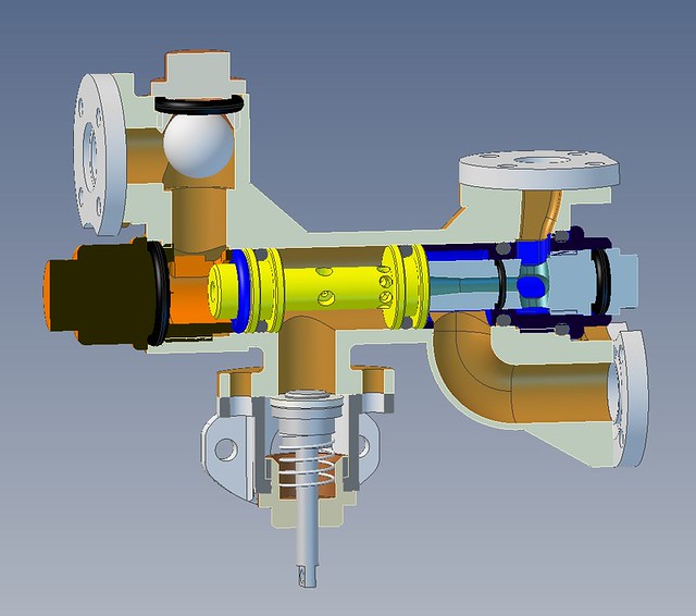 Scale 8X injector sectioned Scale 8X injector sectioned by Georgia Montgomery, on Flickr This is the Steam Cone adjustment arrangement which is quite fiddly to make. This can probably be simplified.  Adjustable steam cone section Adjustable steam cone section by Georgia Montgomery, on Flickr This style of cone works really well, but the LH end can be a little fragile. The drawing shows a slightly beefed up version to overcome that issue. The pockets for the RH overflow are not necessary either although there's no harm in them being there. The parallel portion of the throat can be anything from 0-1mm long without any problems. 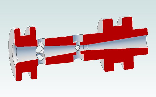 Cone51 Cone51 by Georgia Montgomery, on Flickr |
|
|
|
Post by Roger on Mar 6, 2021 22:45:32 GMT
This is my experimental design for a non-scale body with the One Piece Cone arrangement. It borrows ideas from standard practice, such as the flat faced unions and the way the Steam Cone and end spacer are held in place. The idea is to try to make setting the regulated water flow without moving the Steam Cone. I've deliberately made the regulation gap too big so that the water will need throttling locally with the little valve on the inlet.  Standard 16 fl oz Injector Standard 16 fl oz Injector by Georgia Montgomery, on Flickr Here are a few photos of the process of making the various bits and pieces and the Silver Soldering fixture.  20210303_202311 20210303_202311 by Georgia Montgomery, on Flickr 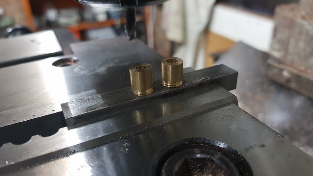 20210303_202907 20210303_202907 by Georgia Montgomery, on Flickr  20210303_212126 20210303_212126 by Georgia Montgomery, on Flickr  20210305_125252 20210305_125252 by Georgia Montgomery, on Flickr  20210305_151547 20210305_151547 by Georgia Montgomery, on Flickr  20210305_151756 20210305_151756 by Georgia Montgomery, on Flickr  20210305_164115 20210305_164115 by Georgia Montgomery, on Flickr  20210305_170025 20210305_170025 by Georgia Montgomery, on Flickr 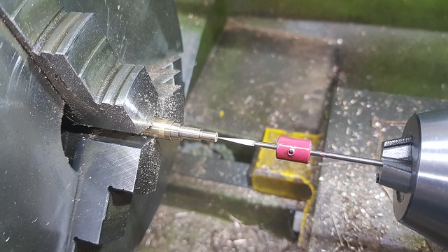 20210305_222514 20210305_222514 by Georgia Montgomery, on Flickr  20210305_222607 20210305_222607 by Georgia Montgomery, on Flickr  20210306_112201 20210306_112201 by Georgia Montgomery, on Flickr The thin strip of Emery paper is removing the worst of the burrs in the hole where the valve goes.  20210306_114750 20210306_114750 by Georgia Montgomery, on Flickr  20210306_114932 20210306_114932 by Georgia Montgomery, on Flickr  20210306_152228 20210306_152228 by Georgia Montgomery, on Flickr  20210306_183727 20210306_183727 by Georgia Montgomery, on Flickr As drawn and made, this didn't work at all. The original regulation gap was 0.33mm and the valve hole was 2.5mm. All this did was blow steam everywhere. The valve hole was then filled in with a Brass plug, and 0.8mm, 1mm and 1.2mm holes tried to no good effect. Clearly the regulation gap can't be that large, so I decreased that to 0.26mm and it works fine with the valve fully open, but doesn't like being throttled. So the valve hole looks about the right size. However, I need to know what dimensions are acceptable, so I drilled out the valve hole to 1.3mm. The Injector still worked, but it needed the valve to be slightly closed for the cleanest operation which indicates that the regulation gap is too large. That's fine, because it can be adjusted. I then reduced the regulation gap to 0.18mm to see what effect that would have, and now the 1.3mm hole seems just right, it doesn't need closing. The regulation gap was further reduced to 0.13mm and this was a step too far, it doesn't work with the 1.3mm hole or closing the valve. I drilled out the valve to 1.4mm, and unsurprisingly this made no difference. So to summarise, the regulation gap can definitely be between 0.18mm and 0.26mm with a valve hole of 1.3mm I've just made a new sleeve to increase the gap again so I can find out the absolute maximum gap it will work with, ie somewhere between 0.33m and 0.26mm It's beginning to look like a valve might not be necessary. It may be that it just needs a removable disc which can have a 1.2mm or 1.3mm hole depending on which end of the tolerance band the gap was made to. I also need to see if opening up the valve hole further prevents it from working correctly. There's no point in it being miles to big because that just makes any adjustment coarser. Anyway, I'm not going to spend much more time on this, I just wanted to get an answer to what alternative arrangements could be used for regulation. I don't want to get bogged down too long because I want to get back to painting the Locomotive. |
|
|
|
Post by Roger on Mar 7, 2021 17:15:00 GMT
I've run more tests today on the Non-scale cone design.
A new sleeve was made to increase the regulation gap to 0.29mm as it turns out. This picks up and works as long as the valve with a 1.4mm hole is slightly closed. I tried this from 90psi and it initally dropped out at 30psi. It then continued down below 25psi with a couple of adjustments to the main water supply valve.
So it's clear that the regulation gap in itself isn't super critical. Anything from 0.29mm to 0.18mm works just fine as long as you can regulate the water reaching the injector.
The valve definitely seems like overkill in its present form. I'm of the opinion that either a simpler valve design would be a better option, or alternatively adding a disc with a hole to the inlet.
|
|


